1
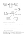
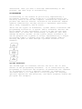
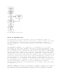
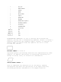
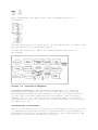
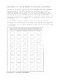
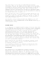
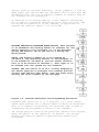
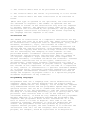
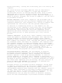
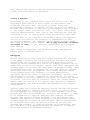
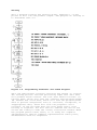
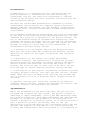
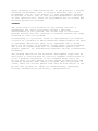
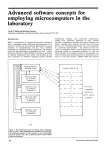
INTRODUCTION TO PROGRAMMING
Problem Solving Concepts, Flowcharting, and Programming
Languages
It is the intent of this manual to provide an introduction to
computer programming, and to the programming language, BASIC
(Beginners All-Purpose Symbolic Instruction Code). BASIC is a
popular programming language, especially for new programmers and
casual computer users. Its conversational nature makes
communicating with computers natural, simple, and
straightforward. Its use of near English words and mathematical
expressions gives the coding a familiar appearance. Also, its
original design, to teach the casual user how to program, makes
it a good language to learn first. For those of you with
computer operations experience, this course is intended to
provide a transition from operations into programming. It will
introduce concepts of programming that apply to other languages
as well as BASIC. For those of you with programming experience,
it will provide a review of programming concepts and introduce
the capabilities of BASIC and its syntax. For those not in data
processing, who have a computer available, it will pro-vide an
introduction to a programming language available on most
computers. When you complete the course, you should understand
the capabilities and syntax of the BASIC language and be able to
write a program.
OVERVIEW OF PROGRAMMING
Before learning to program in the language, BASIC, it is helpful
to establish some context for the productive part of the entire
programming effort. This context comprises the understanding and
agreement that there are four fundamental and discrete steps
involved in solving a problem on a computer. The four steps are:
1. State, analyze, and define the problem.
2. Develop the program logic and prepare a program flowchart or
decision table.
3. Code the program, prepare the code in machine readable form,
prepare test data, and perform debug and test runs.
4. Complete the documentation and prepare operator procedures
for implementation and production.
Figure 1-1 depicts the evolution of a program.
Programming can be complicated, and advance preparation is
required before you can actually start to write or code the
program. The first two steps, problem understanding/definition
and flowcharting, fall into the advance planning phase of
programming. It is important at this point to develop
Figure 1-1. Evolution of a Program.
correct habits and procedures, since this will prevent later
difficulties in pro-gram preparation.
Whether you are working with a systems analyst, a customer, or
solving a problem of your own, it is extremely important that
you have a thorough understanding of the problem.
Every aspect of the problem must be defined:
What is the problem?
What information (or data) is needed?
Where and how will the information be obtained?
What is the desired output?
Starting with only a portion of the information, or an
incomplete definition, will result in having to constantly alter
what has been done to accommodate the additional facts as they
become available. It is easier and more efficient to begin
programming after all of the necessary information is
understood. Once you have a thorough understanding of the
problem, the next step is flowcharting.
FLOWCHARTING
Flowcharting is one method of pictorially representing a
procedural (step-by- step) solution to a problem before you
actually start to write the computer instructions required to
produce the desired results. Flowcharts use different shaped
symbols connected by one-way arrows to represent operations,
data, flow, equipment, and so forth.
There are two types of flowcharts, system (data) flowcharts and
programming flowcharts. A system (data) flowchart defines the
major phases of the processing, as well as the various data
media used. It shows the relationship of numerous jobs that
makeup an entire system. In the system (data) flowchart, an
entire program run or phase is always represented by a single
processing symbol, together with the input/output symbols
showing the path of data through a problem solution. For
example:
System Flowchart
The second type of flowchart and the one we’ll use in this
manual is the programming flowchart. It is constructed by the
programmer to represent the sequence of operations the computer
is to perform to solve a specific problem. It graphically
describes what is to take place in the program. It displays
specific operations and decisions, and their sequence within the
pro-gram. For example:
Programming Flowchart
Tools of Flowcharting
Flowcharting has been defined, and two different types of
flowcharts discussed. We will now take a look at the tools used
in flowcharting. These tools are the fundamental symbols,
graphic symbols, flowcharting template, and the flowcharting
worksheet.
FUNDAMENTAL SYMBOLS. To construct a flowchart, it is first
necessary to know the symbols and their related meanings. They
are standard for the military, as directed by Department of the
Navy Automated Data Systems Documentation Standards, SECNAVINST
5233.1 (Series). Symbols are used to represent functions. These
fundamental functions are processing, decision, input/output,
terminal, flow lines and connector symbol. All flowcharts may be
initially constructed using only these fundamental symbols as a
rough outline to work from. Each symbol corresponds to one of
the functions of a computer and specifies the instruction(s) to
be performed by the computer. The contents of these symbols are
called statements. Samples of these fundamental symbols,
definitions, examples, and explanations of their uses are shown
in figure 1-2.
GRAPHIC SYMBOLS. Within a flowchart, graphic symbols are used to
specify arithmetic operations and relational conditions. The
following are commonly-used arithmetic and relational symbols.
FLOWCHARTING TEMPLATE. To aid in drawing the flowcharting
symbols, you may use a flowcharting template. Figure 1-3 shows a
template containing the standard symbol cutouts. A template is
usually made of plastic with the symbols cut out to allow
tracing the outline.
PROCESS SYMBOL is used to
represent general processing functions not represented by other
symbols. It depicts the process of operations resulting in a
change of value, form, or location of information.
INPUT/OUTPUT SYMBOL is
used to represent any function of an I/O device. Making
information available for processing is an Input function;
recording processed information is an Output function.
DECISION SYMBOL is used to depict a point in a program at which
a branch to one of two or more alternate paths is possible.
TERMINAL, INTERRUPT SYMBOL start, stop, halt, delay, or
interrupt.
CONNECTOR SYMBOL represents a junction in a line of flow to
another part of the flowchart. A common identifier, such as an
alphabetic character, number, or mnemonic label, is placed
within the exit and its associated entry.
FLOWLINE SYMBOL is used to represent flow direction by lines
drawn between symbols. Normal direction of flow is left to right
and top to bottom. If the direction of flow is other than
normal, arrowheads are required at the point of entry.
Divide I by 12 assign value to R.
Enter these values through the terminal, store in locations B,
D, I.
If A is NOT equal to B, take NO branch.
If A is equal to B, take YES branch.
START/STOP flow chart at this point.
This represents the EXIT point and the ENTRY point in a
flowchart.
Initial processing is shown here. If the NO branch is taken, the
processing block is performed again.
If the YES branch is taken, the INPUT/OUTPUT operation is
performed.
Figure 1-3. Flowchart Template.
FLOWCHART WORKSHEET. The Flowchart Worksheet is a means of
standardizing documentation. It provides space for drawing
programming flowcharts and contains an area for identification
of the job, including application, procedure, date and page
numbers (fig. 1-4). You may find it helpful when you develop
flowcharts. If you don’t have this form available, a plain piece
of paper will do.
Constructing a Flowchart
There is no "best way" to construct a flowchart. There is no way
to standardize problem solution. Flowcharting and programming
techniques are often unique and conform to the individual’s own
methods or direction of problem solution.
This manual will show an example of developing a programming
flowchart. It is not the intent to say this is the best way;
rather, it is one way to do it. By following this text example
you should grasp the idea of solving problems through flowchart
construction. As you gain experience and familiarity with a
computer system, these ideas will serve as a foundation. In
order to develop a flowchart, you must first know what problem
you are to solve. It is then your job to study the problem
definition and develop a flowchart to show the logic, steps, and
sequence of steps the computer is to execute in order to solve
the problem.
As an example, suppose you have taken a short-term second
mortgage on a new home, and you want to determine what your real
costs will be: the amount of interest; the amount to be applied
to principal; and the final payment at the end of the three year
loan period.
Figure 1-4. Flowchart Worksheet.
The first step is to be sure you understand the problem
completely. What are the inputs and the outputs and what steps
are needed to answer the questions? Even when you are specifying
a problem of your own, you’ll find we don’t usually think in
small detailed sequential steps. But, that is exactly how a
computer operates; one step after another in a specified order.
Therefore, it is necessary for you to think the problem solution
through step-by- step. You might clarify the problem as shown by
the Problem Definition in figure 1-5.
After you have this level of narrative problem definition, you
are ready to develop a flowchart showing the logic, steps, and
sequence of steps you want the computer to execute in order to
solve the problem. A programming flowchart of this problem is
also shown in figure 1-5.
You now have a plan of what you want the computer to do. The
next step is to code a program that can be translated by a
computer into a set of instructions it can execute. This step is
called program coding.
PROGRAM CODING
It is important to remember program coding is not the first step
of programming. Too often we have a tendency to start coding too
soon. As we discussed earlier, there is a great deal of planning
and preparation to be done prior to sitting down to code the
computer instructions to solve a problem. For the example
amortization problem (fig. 1-5), we have analyzed the
specifications in terms of (1) the output desired; (2) the
operations and procedures required to produce the output; and
(3) the input data needed. In conjunction with this analysis, we
have developed a programming flowchart which outlines the
procedures for taking the input data and processing it into
usable output. You are now ready to code the instructions that
will control the computer during processing. This requires that
you know a programming language.
Before getting into the specific programming language called
BASIC, it may be helpful to have a greater understanding of
programming languages in general.
All programming languages are composed of instructions that
enable the computer to process a particular application, or
perform a particular function.
Instructions
The instruction is the fundamental element in program
preparation. Like a sentence, an instruction consists of a
subject and a predicate. However, the subject is usually not
specifically mentioned; rather it is some implied part of the
computer system directed to execute the command that is given.
For example, the chief tells a sailor to "dump the trash." The
sailor will interpret this instruction correctly even though the
subject "you" is omitted. Similarly, if the computer is told to,
"ADD 1234," the control unit may interpret this to mean that the
arithmetic-logic unit is to add the contents of address 1234 to
the contents of the accumulator.
In addition to an implied subject, every computer instruction
has an explicit predicate consisting of at least two parts. The
first part is referred to as the command, or operation; it
answers the question "what?. " It tells the
PROBLEM DEFINITION MORTGAGE AMORTIZATION This program
is to determine the monthly amount of interest (A) and
amount applied to the principal (P) of the mortgage
giving the balance (B) at the end of a thirty-six
month period.
INPUT: The monthly payment is to be entered as
variable D, the beginning balance of the mortgage is
to be entered as variable B, and the annual interest
rate is to be entered as variable I. This input is to
be entered into the system via the terminal.
OUTPUT: The end result is to be a listing displaying
the amount applied to principal and interest and the
current loan balance each month, with one final entry
showing the final payment on the mortgage.
Figure 1-5. Problem Definition and Programming Flowchart.
computer what operation it is to perform; i.e., read, print,
input. Each machine has a limited number of built-in operations
that it is capable of executing. An operation code is used to
communicate the programmer’s intent to the computer.
The second specific part of the predicate, known as the operand
names the object of the operation. In general, the operand
answers the question "where?." Operands may indicate the
following:
1. The location where data to be processed is found.
2. The location where the result of processing is to be stored.
3. The location where the next instruction to be executed is
found.
(When this type of operand is not specified, the instructions
are executed in sequence.) The number of operands and the
structure or format of the instructions vary from one computer
to another. However, the operation always comes first in the
instruction and is followed by the operand(s). The programmer
must prepare instructions according to the format required by
the language and the computer to be used.
Instruction Set
The number of instructions in a computer’s instruction set may
range from less than 30 to more than 100. These instructions may
be classified into categories such as input/output (I/O), data
movement, arithmetic, logic, and transfer of control.
Input/output instructions are used to communicate between I/O
devices and the central processor. Data movement instructions
are used for copying data from one storage location to another
and for rearranging and changing of data elements in some
prescribed manner. Arithmetic instructions permit addition,
subtraction, multiplication, and division. They are common in
all digital computers. Logic instructions allow comparison
between variables, or between variables and constants. Transfer
of control instructions are of two types, conditional or
unconditional. Conditional transfer instructions are used to
branch or change the sequence of program control, depending on
the outcome of the comparison. If the out-come of a comparison
is true, control is transferred to a specific statement number;
if it proves false, processing continues sequentially through
the program. Unconditional transfer instructions are used to
change the sequence of program control to a specified program
statement regardless of any condition.
Programming Languages
Programmers must use a language that can be understood by the
computer. There are several methods that can achieve humancomputer communication. For example, let us assume the computer
only understands French and the programmer speaks English. The
question arises: How are we to communicate with the computer?
One approach is for the programmer to code the instructions with
the help of a translating dictionary prior to giving them to the
processor. This would be fine so far as the computer is
concerned; however, it would be very awkward for the programmer.
Another approach is a compromise between the programmer and
computer. The programmer first writes instructions in a code
that is easier to relate to English. This code is not the
computer’s language; therefore, it does not understand the
orders. The programmer solves this problem by giving the
computer another program, one that enables it to translate the
instruction code into its own language. This translation
program, for example, would be equivalent to an English-to-
French dictionary, leaving the translating job to be done by the
computer.
The third and most desirable approach from an individual’s
standpoint, is for the computer to accept and interpret
instructions written in everyday English terms. Each of these
approaches has its place in the evolution of programming
languages and is used in computers today. The first approach is
known as machine language, the second as symbolic, and the third
as procedure-oriented.
MACHINE LANGUAGES. With early computers, the programmer had to
translate instructions into the machine language form that the
computers understood. This language was a string of numbers that
represented the instruction code and operand address(es).
In addition to remembering dozens of code numbers for the
instructions in the computer’s instruction set, the programmer
also had to keep track of the storage locations of data and
instructions. This process was very time consuming, quite
expensive and often resulted in errors. Correcting errors or
making modifications to these programs was a very tedious
process.
SYMBOLIC LANGUAGES. In the early 1950s, mnemonic instruction
codes and symbolic addresses were developed. This improved the
program preparation process by substituting letter symbols
(mnemonic codes) for basic machine language instruction codes.
Each computer has mnemonic code, although the symbols vary among
the different makes and models of computers. The computer still
uses machine language in actual processing, but it translates
the symbolic language into machine language equivalent. Symbolic
languages have many advantages over machine language coding in
that less time is required to write a program, detail is
reduced, and fewer errors are made. Errors which are made are
easier to find, and programs are easier to modify.
PROCEDURE-ORIENTED LANGUAGES. The development of mnemonic
techniques and macroinstructions led to the development of
procedure-oriented languages. These languages are oriented
toward a specific class of processing problems. A class of
similar problems is isolated, and a language is developed to
process these types of applications. Several languages have been
designed to process problems of a scientific-mathematical nature
and others that emphasize file processing. The most familiar of
these are BASIC and FORTRAN for scientific or mathematical
problems, and COBOL for file processing.
Programs written in procedure-oriented languages, unlike those
in symbolic languages, may be used with a number of different
computer makes and models. This feature greatly reduces
reprogramming expenses when changing from one computer system to
another. Other advantages to procedure-oriented languages are:
(1) they are easier to learn than symbolic languages; (2) they
require less time to write; (3) they provide better
documentation; and (4) they are easier to maintain. However,
there are some disadvantages of procedure-oriented languages.
They require more space in memory and they process data at a
slower rate than symbolic languages.
Coding a Program
Regardless of the language used, there are strict rules the
programmer must adhere to with regard to punctuation and
statement structure when coding any program. Using the
programming flowchart introduced earlier, we have now added a
program coded in BASIC to show the relationship of the flowchart
to the actual coded instructions (fig. 1-6). Don’t worry about
complete understanding, just look at the instructions with the
flowchart to get an idea of what coded instructions look like.
You will have to have specific information about the computer
you are to use and how the language is implemented on that
particular computer. The computer manufacturers provide these
specifics in their user’s manual. Get a copy and study it before
you begin to code. To you, but they may prevent your program
from running.
Once coding is completed, the program must be debugged and
tested prior to implementation.
Debugging
Errors caused by faulty logic and coding mistakes are referred
to as "bugs." Finding and correcting these mistakes and errors
that prevent the program from running and producing correct
output is called "debugging." Rarely do complex programs run to
completion on the first attempt. Often, time spent debugging and
testing equals or exceeds the time spent in program coding. This
is particularly true if insufficient time was spent on problem
definition and logic development. Some common mistakes which
cause program bugs are: mistakes in coding punctuation,
incorrect operation codes, transposed characters, keying errors
and failure to provide a sequence of instructions (a program
path) needed to process certain conditions. To reduce the number
of errors, you will want to carefully check the coding sheets
before they are turned in for keying. This process is known as
"desk-checking" and should include an examination for program
completeness.
Typical input data should be manually traced through the program
processing paths to identify possible errors. In effect, you
will be attempting to play the role of the computer. After the
program has been desk-checked for accuracy, the program is ready
to be assembled or compiled. Assembly and compiler programs
prepare your program (source program) to be executed by the
computer and they have error diagnostic features which detect
certain types of mistakes in your program. These mistakes must
be corrected. Even when an error-free pass of the program
through the assembly or compiler program is accomplished, this
does not mean your program is perfected. However, it usually
means the program is ready for testing.
Testing
Once a program reaches the testing stage, generally, it has
proven it will run and produce output. The purpose of testing is
to determine that all
Figure 1-6. Programming Flowchart and Coded Program.
data can reprocessed correctly and that the output is correct.
The testing process involves processing input test data that
will produce known results. The test data should include: (1)
typical data, which will test the commonly used program paths;
(2) unusual but valid data, which will test the program paths
used to process exceptions; and (3) incorrect, incomplete, or
inappropriate data, which will test the program’s error
routines. If the pro-gram does not pass these tests, more
testing is required. You will have to examine the errors and
review the coding to make the coding corrections needed. When
the program passes these tests, it is ready for computer
implementation. Before computer implementation takes place,
documentation must be completed.
Documentation
Documentation is a continuous process, beginning with the
problem definition. Documentation involves collecting,
organizing, storing, and other-wise maintaining a complete
record of the programs and other documents associated with the
data processing system.
The Navy has established documentation standards to ensure
completeness and uniformity for computer system information
between commands and between civilian and Navy organizations.
SECNAVINST 5233.1 (Series) establishes minimum documentation
requirements.
Local minimum documentation requirements are usually established
by the head of the data processing department/division. At most
commands this function is delegated to the project manager. The
key to the minimum amount of documentation required by local
commands should be the amount that is required for replacement
personnel to understand input, processing, and output for each
program or system for which they will be responsible. A
documentation package should include:
1. A definition of the problem. Why was the program written?
What were the objectives? Who requested the program, and who
approved it? These are the types of questions that should be
answered.
2. A description of the system. The system environment
(hardware, software, and organization) in which the program
functions should be described (including systems flowcharts).
General systems specifications outlining the scope of the
problem, the form and type of input data to be used, and the
form and type of output required should be clearly defined.
3. A description of the program. Programming flowcharts, program
listings, program controls, test data and test results, storage
dumps these and other documents that describe the program and
give a historical record of problems and/or changes should be
included.
4. Operator instructions. Items that should be included are
computer switch settings, loading and unloading procedures, and
starting, running, and termination procedures.
Implementation
After the documentation has been completed, and the user has
reviewed and accepted the test output, the project request is
submitted to upper management, usually the ADP department head,
for production approval. Once upper management has approved the
program, it can be put into production. If a program is to
replace a program in an existing system, it is generally wise to
have a period of parallel processing; that is, the job
application is processed both by the old program and by the new
program. The purpose of this period is to verify processing
accuracy and completeness. Once the program is in production it
maybe necessary to make modifications to the program to satisfy
changing requirements. This is another important duty of the
programmer, and it is not unusual to find programmers spending
25 percent of their time on this program maintenance activity.
In some installations, there are programmers who do nothing but
maintain production programs.
SUMMARY
The first step in the solution of any problem involves a
fundamental but often overlooked concept a thorough
understanding of the problem. The second step in successful
problem solving involves creating a flowchart showing the steps
required to solve the problem.
Flowcharting is a pictorial means of representing a procedural
solution to a problem in which different shaped symbols are used
to represent operations, data, flow, equipment and so forth.
There are two types of flowcharts system (data) and programming.
The tools of flowcharting are: (1) fundamental symbols; (2)
graphic symbols; (3) flowcharting template; and (4) flowcharting
worksheet.
The problem definition and flowchart development steps must be
done prior to sitting down to code the computer instructions to
solve a problem. Regardless of the language used, there are
strict rules you must adhere to with regard to punctuation and
statement structure when coding a program. Once the program is
coded, there are several phases that must be done before it can
be put into production. These are desk-checking, debugging,
testing, documentation and finally, implementation.