1
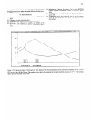
73s
An Interactive Graphical Model For The Design And Control Of A Transfer Line
Mark Plesko”
Sincrotrone Trieste
Padriciano 99, I-34012 TRIESTE
e-mail: [email protected]
the dipole magnet). When the currents of the magnetic
elements are being varied, knobby always keeps the initial
An interactive model for the beam transport along a conditions fixed and transforms the beam ellipses upstream and
downstream of the element where the initial conditions are
transfer line with graphical output is presented. The model
delined
allows to interactively vary quadrupole and dipole currents as
The following three initial conditions are taken:
well as the initial beam parameters (sigma matrix, dispersion
the maximal transverse dimension of the b-camellipse
Ymax
and energy spread) by means of analog knobs used otherwise
(i.e. the starting value of the beam cnvclope)
by CAD software. The resulting beam envelope is displayed
(ymax)’ the slope at the point of the maximal transverse
graphically in quasi real time. Actual magnet currents can be
dimension of the beam ellipse (i.e. the starting slope
read from or written to the field by means of a remote
of the beam envelope)
procedure call. The model runs under Xl 1 windows.
the slope at the point y=O of the beam ellipse (i.e.
(Y’h
the slope of the particle which goes through the beam
caltre)
I. INTRODUCTION
Here y stands for either the horizontal direction (x) or the
The model is applicable for the design of a transfer line. and vertical (z). In terms of Twiss parameters, the following
during its commissioning and control. It displays the beam relations hold [ 11:
envelope in the horizontal and in the vertical plane for a given
lattice and given initial conditions of the beam. In addition,
y’()
=: F/i
ymax’
= -Cf. l/Tmax
= &ji
Y
the user can use knobs to vary the currents in the magnets of
the transfer line and he/she gets an immediate response.
The knobs can be used also to vary the initial conditions of
These parameters have been chosen, because they represent
the beam at any given point along the transfer lint and also to
the
most intuitive set of variables for the. display of the beam
vary the energy spread and the dispersion vector. Thus the user
envelope.
They are directly related to the graphical output.
has a complete interactive control over the parameters of the.
The
initial
dispersion D, its derivative D’ and the energy
model, which is therefore called knobby.
spread
dp/p
are
used for modelling the off-energy envelope of’
Along with other features, the model reads or writes the
the
beam.
currents of the power supplies directly from the control
system. The beam envelope is calculated by matrix B. The Structure of the Transfer Line
multiplication [l]. The graphical output which is in colours
The transfer line consists of elements, which may bc
and the knob event handling is performed with the package
Klib [2] under X11 windows on an HP-BOO work station magnetic (dipoles or quadrupole), drift spacesor labels of xro
length (monitors or fluorescent screens). Magnetic elements
computer.
may be grouped into families. A family is considered a set of
II. THE PARAMETERS OF THE MODEL
magnetic elements, which have the same optical properties and
are powered in series by a single power supply.
The knobs which vary the element strengths are actually
A. The Initial Conditions
assigned to families (i.e. power supplies), thus several
The initial conditions define the horizontal dispersion and elements can be varied simultaneously with one knob.
the beam ellipse in both planes. Knobby allows the initial
The input parameters for the elements are same as the ones
conditions to be defined at any element along the transfer line, used in TRANSPORT 131,Currently the only type of magnets
not only at the first one. This is useful when the beam that arc recognized by knobby are normal quadrupoles and
conditions are determined by a measurement, which is usually rectangular horizontal bending magnets, which may have a
related to an element somewhere in the transfer line. It is also gradient superimposed. No skew elements are used.
needed to match the transfer line to a given exit condition or to
In contrast to an off-line model like TRANSPORT, also
certain conditions in the transfer line (e.g. given beam sizes in the actual currents of the power supplies have to be given. The
actual current of a power supply may be read in from the
hardware if knobby is connected to a real transfer line or given
* Supportedby an ICTP fellowship.
Abstract
736
as input parameter in case knobby is used during the design
phase. For the former, an additional value has to be given
which gives the maximal current a power supply can provide.
This value is important to prevent a current, which would
exceed the capabilities of the power supply, to be applied.
The elements of the types fluorescent screen and monitor
have zero field, zero length and zero current. These types are
used to indi’cate the position of a point where the beam
envelope can be measured. In the graphical output of knobby,
this is shown as vertical green line.
C. The Graphical
Outpur
The graphical output of knobby is directed into a special
window, which is opened and closed during run-time. In order
to minimize the drawing time and thus to avoid flickering,
only the mosf. important information is given. The size of the
envelope is plotted for five points in each element. This might
not be very accurate for long drift spaces, but it is a good
compromise between time and resolution, since the exact
beam size in drift cells is usually not of interest. If a better
resolution is wanted, the drift cell can always be split in two
or more. The vertical axis is labeled, while the horizontal is
not. On the abscise only the boxes representing the positions
and sizes of the magnetic elemcntc; are shown, All lengths arc
displayed to scale.
Below the boxes of the magnetic elements the currents of
their power supplies are shown. By varying the corresponding
knobs also these values change accordingly and the new
calculated envelopes are displayed immediately.
The horizontal and vertical envelopes are drawn on the
same graph with different colours. The horizontal envelope is
shown twice to emphasize the difference between on- and offenergy particles. The envelope for on-energy particles
(i.e.without dispersion) is displayed in dark blue, the
horizontal envelope including dispersion is shown in light
blue. The colour of the vertic.al envelope is red.
III. THE FEATURES OF THE MODEL
Here, only the most interesting features are described. See
reference [4] for a detail description of the model’s usage.
A. The Modes of Operation
The default mode is the simulation
mode. In this mode
the initial settings of the magnetic elcmcnts arc read from the
input file and the user may change the strengths via knobs.
If the user wan& to see the expected envelope due to the
real magnetic fields in the magnetic elements, he/she selects
the real mode. In this mode the currents are read in from the
hardware via the remote procedure call mechanism [5] when
the graphic window is opened first. After that, the user may
again use the knobs to simulate different currents. The real
currents are read in only once after each request.
The apply mode is selected after a setting has been
achieved with- the model, which should be realizedon the real
transfer line. Then the values of the currents in the model are
applied to the hardware via a remote procedure call. Knobby
checks first if the selected currents do not exceed the maximal
allowed currents that were given in the input file. Only the
currents whose absolute values are below the maximum arc
applied. For the others, a warning is issued in the terminal
window. After the apply is performed, knobby goes back into
the simulation mode and allows the user to turn the knobs
again. For a new setting of the hardware, another apply must
be issued.
The user may want to print an envelope plol on a color or
b&w plotter/printer. The print mode changes the colours of
the current graphic window for a better printing contrast. The
screen hardcopy is done by the user with Xl 1 commands.
B. The Use of Knobs
For the HP work stations there exists a panel with nine
quasi analog knobs for the use of CAD software. With these
knobs the currents in the power supplies of the magnetic
elements are simulated. The knobs have no upper or lower
limits, thus all possible currents may be set.
The knobs may be used also to change. rhc initial
conditions. The user assigns three knobs, one to each
parameter y,,, , (Ymax)’ and (y’)~ with y being x or z,
respectively. If another option is selected, the three knobs are
assigned to dp/p, D and D’ for changing the initial conditions
of the off-energy particles.
When the graphic window is opened the three bottom
knobs of the nine knob panel may be turned to change the
initial conditions in quasi real time. In the top left comer of
the window the current values of the initial conditions arc
displayed.
Due to the limited number of knobs, only on set of initial
conditions may be changed at a time. If more than six power
supplies (i.c. magnetic clement families) arc present and the
knob control of the initial conditions is requested, then only
the first six families may be controlled by the knobs of the
knob panel, as the last three knobs are reserved for the initial
conditions.
IV.THEAPPLICATION OFKNOBBY AI‘ ELETI'RA
ELECTRA is a third generation synchrotron light source
being built at Trieste 161.Knobby will be used to operate the
transfer line from the full energy linac to the storage ring, in
particular during the commissioning of the linac and the
transfer line. Although knobby is a general program. which
can take any lattice from an input file, some details are
nevertheless specific for the equipment at ELETTRA.
The model knobby has been already successfully used to
developed the optics layout (see figure 1) of the diagnostic linr
for the commissioning of the 30-100 MeV linac [7] and to
operate the diagnostic line during emittance measurements.
v. ACKN~WLEM;EMENTS
I gratefully acknowledge the help of Franc0 Potepan who
provided me with the powerful Klib package which he has
737
developed for his personal use. I also thank Carlo Bocchetta
for suggestions how to make the model efficient for the users.
VI. REFERENCES
[l]
KSteffen, Basic Course on Accelerakw Oprics, CERN 85-19,
.,--.
1985
[2] F.Potepan. private communication.
[3] K.L.Brown et al., TRANSPORT, CERN 80-04, 1980.
[4] M.Plesko. User Manual
for
knobby, rhe Model of fhe
Diagnosric Line. Sincrotrone Tricste, ST/M-92/4, March
1992.
[5] M.Mignacco.
Remote Procedure
Call
in the ELETTRA
Conrrol System. Sincrotrone Trieste. ST/M-89/4, March
1989.
[6] ELE’ITRA Conceptual Design Report. Sincrotrone Trieste,
April 1989.
[7] C.J.Bocchettaet al., The Diqnosric
Tesrs of the ELEl”l’RA
proceedings.
Line for rhe Acceptance
100 MeV Pre-injector,
these
, ;!Gj;,‘.;:~,:,i,‘,r,,l,,!i,!l;l,‘l”liili.’,il;,’,,~,
‘, lj ’ : Iii‘, ,,“‘(‘qit;,j/:;!il’$‘.,
‘l.i1~@1’:
I,/, J 4 , : ,(I, f ! : //jj!‘I.,
/,.j’ll$
1-q,,ih
IIf ;-
1,::/,m
I, ,i,“<‘,
5
4
~~~~~“‘~
3
2
I-.-;---::
l-
I
12.000.00-8.10
-8200.00225
Figure 1. The be;lm envelope in the diagnostic line optimized for the measurement of the horizontal cmittance for the 75 MeV
FEL mode of the 100 MeV linac. The numbers given below the magnets are the pole tip fields in units of 10m2T. The ordinate
labels stand for the beam size in mm.