1
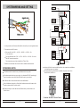
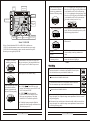
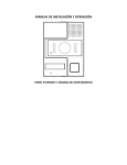
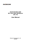
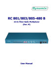
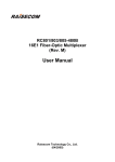
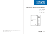
Video Door Phone Outdoor Camera
-- KW-138EA User's Manual
Top Way Intelligent Science & Technology Co., Ltd
http://www.kenwei.com
CONTENTS
Product Introduction
Features and Parts
Installation
PRODUCT INTRODUCTION
3
4
Thank you for purchasing our products of building intercom system series.Please
read the instructions carefully and follow the directions before install the products.
Any problem regarding to the product,please query your supplier.
5
KW-138EA Sketch Map
Installation Range
Installation Attention
System Wiring and Setting
System Wiring Sketch
Guard Room Connection
Distributor Connection Terminal
Configuration of Distributor
Jumper
Video Setup
Floor No. Setting
Connecting and Configure Between Indoor Monitor and Distributor
Wiring Between Outdoor Unit and Distributor
Wiring Between Distributor and Indoor Monitor
The Connection Between Distributor
Operation Guide
Initial Room No. And addressed port No. Setting form for KW-138EA
Administrator menu
Administrator mode -- password setup
Administrator mode -- unit setup
Administrator mode -- RF card management
Administrator mode -- model No.and publishing date of software display
Administrator password initialization
Call and unlock
False Malfunction
Parameters
Words Explanation
5
6
GENERAL FEATURES:
7
Simple wiring, only use one ethernet cable to connect the whole system,
reduce the cost of installation and maintenance.
8
8
10
10
11
11
13
14
15
15
16
17
18
18
18
19
19
21
23
23
23
25
Press the relevant room number to talk with indoor monitor directly.
Indoor unit could monitor the outdoor condition and hear the voice.
Unlock the door by ID card, password, or remote unlock from indoor monitor.
Display the current time and operation status on the outdoor camera
Able to change the unlock password with your need
Max. support 64 units indoor monitor (support totally 16 layers, each layer with 4 users)
Max. support 1000pcs ID card
Light induction, auto switch the external connected lamps according to the outdoor
light intension. (to reach this function, need connect KW-516EA)
Support connecting guard room, use 4 wires connection terminal.
To avoid the risk of electric shock, please don't remove cover or back.
Please ask professional person if maintenance needed.
Remind users that important operation and maintenance guides are
included in the attached user's manual.
26
26
2
* KENWEI reserves the right to change or modify design,features,functions
and specifications without any prior notice for the improvement and promotion
of products quality.
3
FEATURES AND PARTS
INSTALLATION
KW-138EA FEATURES AND PARTS
KW-138EA SKETCH MAP
(Unit:mm)
Wall box
35
24
110
11
Expansion Plug
Main Unit
1
“L” Wrench
2
3
280
5
7
8
9
10
Dimension
1.Burglarproof screw
2.Camera(Colour/B&W CCD)
3.Light for Night Vision
4.Speaker
5.LED Display
6.Card Reader
7.Microphone
8.Operation LED / Green
9.Operation LED / Red
10.Number Buttons
11.Angle Adjustment
6
Accessories:
Burglarproof
screw
"L" Wrench
Burglarproof screw
Installation step:
Expansion Plug
Power adaptor
Short circuit cover
4
ID Card
Frequency 125KHz
1.At the selected mounting location,(the dimension as the picture show),
fixed 2 expansion plug.
2.Connect the wire correctly.
3.Use the "L" wrench to tight the unit with screws.The installation has done.
5
267 . 3mm
4
INSTALLATION ATTENTION
INSTALLATION RANGE
(Unit:cm)
1.Do not expose the unit to sunshine or rain:
Even if you do not use it,don't expose it to sunshine or rain.
65
2.Do not expose to intense light:
Spotlight may cause stain or striation in the screen.
3.Do not disassemble the unit by yourself:
Improper disassembly may damage the unit or cause electric shock.
115
160
4.Do not splash water on the unit:
Install the unit in dry place.In case that the unit gets wet,turn off the unit and contact your
dealer.
5.Check the ambient temperature and humidity:
Avoid using the unit where the temperature in hotter or colder than specified,otherwise the
internal parts may get affected.Special care is required to use the unit at high temperature
and humidity.
50
Installation range
6.In case of trouble:
If any trouble occurs while you are using the unit,turn off the power and contact your dealer
to avoid worse problem or unpredictable accident.
7.About operation:
Keep the unit away from magnetic equipments such as microwave oven or big speaker.If the
unit will not be used for a long time,please switch it off.
8.About clean:
Use soft cloth to clean the unit.Do not use any impregnant,such as alcohol,benzene.If you
have any problem,please contact your dealer.
160
°
55
*
50
Camera angles(Vertical)
6
Remark:
When you choose the place to install the unit,please pay attention to:
Keep sufficient space for ventilation and easy communication.
Keep sufficient space to adjust while installing.
Don't put hot resource under the unit.
7
FLOOR 5
SYSTEM WIRING AND SETTING
Indoor Monitor
ply
r Sup
Indoor Monitor
FLOOR 3
Ethernet
Cable
Indoor Monitor
(Communication、
Signal 、
Power Supply)
Indoor Monitor
FLOOR 4
Powe
Distributor
Indoor Monitor
ply
r Sup
Powe
Indoor Monitor
Indoor Monitor
ply
r Sup
Distributor
2.Then check the cable DC resistance:
3.Prohibit to use the Ethernet cable if one of the above conditions cannot be matched.
SYSTEM WIRING SKETCH
The outdoor unit can be connected to any 4 wired indoor monitor we produce.
Indoor Monitor
Ethernet
Cable
Take out cable another side: O/W←→O, GW←→B, B/W←→G, Br/W←→Br 4 wires,
check DC resistance between them.
The resistance between each wires should be less 75ohm / 100m.
Indoor Monitor
Indoor Monitor
Indoor Monitor
Outdoor
Camera
Powe
FLOOR 1
1.As the picture shows, the Ethernet cable should be with mask layer, to avoid signal interference.
Take out cable 1 side: O/W←→O, G/W←→B, B/W←→G, Br/W←→Br
4 wires short circuit
(Communication、
Signal 、
Power Supply)
Ethernet
Cable
Indoor Monitor
FLOOR 2
Distributor
Separate Power
Supply for
Outdoor Camera
Sketch 1
As showed in Sketch 1, monitors in different floors can be connected to one distributor.
(each distributor support 4pcs monitor)
The last distributor (gray one in Sketch 1) should be set specially, please refer to
Sketch 9,Sketch 10 and Form 3.
Each indoor monitor has their own power supply, or by distributor KW-838B, no need supply
power from outdoor camera, which reduce the outdoor camera's power overload.
Use Ethernet cable to connect between outdoor camera and distributor.
If one of distributors is damaged, it will only affect the indoor monitors which connect with it,
the other monitors would be worked as normal.
Transmission the power, audio, and video in one Ethernet cable, just connect them as the
Sketch 1 shows.
Sketch 2
Connection Terminals of Outdoor Camera
8
9
Sketch 3
Input of the
distributor
4
3
Sketch 4
KW-838 TERMINALS
The top of left
connector is
the first pin
2
4 connector to
connect 4pcs
indoor monitor.
Number 1,2,3,4
means the number
of indoor monitor.
Both of terminals could be used under
more distributor condition.
485A
Sketch 6
1...4
GND
1 distributor control 4 indoor monitors,
the monitor's number is refer to the
number on distributor.
Audio
Video
Sketch 7 KW-838
Connection terminal
to indoor monitor
Indoor_VCC
Each distributor KW-838 have 4
connection terminal for indoor monitor.
They are the same function.
Each distributor KW-838B have 4
connection terminal for indoor monitor.
They are the same function.
1 distributor control 4 indoor monitors,
the monitor's number is refer to the
number on distributor.
KW-838B has 2 more connection
terminal than KW-838. One is DC12V,
another one is GND, they supply the
power to indoor monitors.
1...6
Sketch 8 KW-838B
Connection terminal
to indoor monitor
Form 2
CONFIGURATION OF DISTRIBUTOR
Jumper
Open the distributor, you can see the main body of it, with many connectors and jumpers.
The top of right
connector is
the first pin
1
VO+
485B
GND
Output of the
distributor
The left input terminal connect to
outdoor camera or its front distributor,
the right output terminal connect to its
next distributor.
VO-
Audio
1
GND
AO-
Video
2
AO+18V
There are 2 main connection terminal,
but with different connection sequence.
AO+
Indoor_VCC
1 2 3 4
AO+
GND
1 2 3 4
Right connection
terminal:
the top one
is 1st pin
VO-
+18V
DC12V
1 2 3 4
ON
VO+
GND
1...8
ON
485B
1...8
ON
Distributor
connection terminal
to indoor monitor
Left connection
terminal:
the top one
is 1st pin
485A
Distributor output terminal
DISTRIBUTOR CONNECTION TERMINAL
Distributor
connection terminal
to indoor monitor
Use 4 wires standard connection terminal to connect guard room with outdoor camera.
We must use 75Ωvideo cable to connect because of the long distance between guard room
and outdoor camera. Could choose our 4 wires indoor monitor as guard room.
Distributor input terminal
Distributor main connection
terminal to outdoor
camera / another distributor
GUARD ROOM CONNECTION
Jumper 1
S3 video line balance
setup switch
S2 floor
setup switch
ON
1 2 3 4
ON
1 2 3 4
S1 video attenuation
setup switch
ON
1 2 3 4
ON
1 2 3 4
ON
Input of the
distributor
1 2 3 4
VR 3
4
VR 1
TX RX indicator
VR 2
3
Sketch 5 KW-838B TERMINALS
10
Output of the
distributor
4 connector to connect
4pcs indoor monitor.
Number 1,2,3,4 means
the number of indoor
monitor.
image contrast
adjustment
VR2 sidetone
adjust potentiometer
Don't touch VR1
potentiometer
Sketch 9 KW-838
11
indicator for successful
connecting with user
video attenuation
setup switch
Jumper 1
floor
setup switch
Video attenuation setup switch.
Each terminal has different
function, pay attention to the
direction of ON during setting.
ON
TX RX indicator
1 2 3 4
ON
1 2 3 4
NO
VR 3
image contrast
adjustment
VR 1
VR 2
4 3 2 1
VR2 sidetone
Don't touch VR1
potentiometer adjust potentiometer
Video line
balance setup
switch
ON
2
3
4
1
2
3
4
image contrast adjustment
After installation, adjust this potentiometer for image
quality. With video attenuation setup switch, you can
adjust the image quality to the best.
Sidetone adjust potentiometer
Adjust the volume of sidetone, suitable for different
indoor monitor.
Tx LED
If it flashes, means the indoor monitor and outdoor
camera is talking, no need pay attention to this
status.
If the outdoor camera is talking with one of indoor
monitor, this indicator is lighting on.
indicator for successful
connecting with user
We have 2 kinds of distributor, KW-838 and KW-838B, the difference are:
1.KW-838: each indoor monitor it connect, need connect their own power supply.
2.KW-838B: all of indoor monitors it connect, no need connect their own power.
Monitor's power are supplied by KW-838B.
Rx LED
Floor number setup.
ON
1
Sketch 10 KW-838B
Jumper 1,485 terminal
matching resistance setup.
1~2: Use for enhancing the video signal range. Valid
when it is set ON. Usually use for long Ethernet cable.
1 and 2 should be set OFF or ON at the same time.
3~4: Use for weakening the video signal range. Valid
when it is set ON.Usually use for short Ethernet cable.
3 and 4 should be set OFF or ON at the same time.
This switch can be only set as this 2 way.
If this distributor is the last one in the system, like
the grey one in picture 1, the jumper should be short
circuit, or open circuit. The default is open circuit.
Details please see “Floor Number Setting”
LED of successful
connecting with user
Form 3
Video Setup
If this KW-838 is the last distributor of the system, which like the gray
one showed in sketch 1, or when there is only one KW-838 in the system,
the video line balance setup switch should be dialed as this
ON
1
2
3
4
1
2
3
4
1
2
3
4
1
2
3
4
ON
Otherwise the switch should be dialed as this:
Video line balance setup switch.
Each terminal has different
function, pay attention to the
direction of ON during setting.
3~4: VIDEO
, :75ohm GND short circuit
position. This terminal you can set all of OFF, or all
of ON. Usually set all of OFF.
2: VIDEO , 75ohm video input load.
If this distributor is the last one in the system,
like the grey one in the picture 2, the jumper
should be set ON. The default is open circuit.
1: Video high frequency strengthen. Make this
terminal short circuit, the image could be more clear.
The default jumper set ON.
12
If the distance between one KW-838 and outdoor camera is within 60m,
the video attenuation setup switch should be dialed as this:
ON
ON
Otherwise the switch should be dialed as:
After meet the above 4 requirement, if the contrast is too high, usually because of the high
range video signal. You can adjust the image contrast potentiometer clockwise, to make
the good image quality.
If the contrast is lower, and the picture is distorted vertically, usually because of the low
range video signal. You can adjust the image contrast potentiometer counter-clockwise,
to make the good image quality.
13
Warning:
ON
Do not adjust the potentiometer VR1 on picture 9/10
or it may cause the malfunction of the system.
No need adjust after factory setting.
Floor number setting
2
3
4
1
2
3
4
1
2
3
4
1
2
3
4
13
OFF
OFF
ON
ON
14
OFF
OFF
ON
OFF
15
OFF
OFF
OFF
ON
16
OFF
OFF
OFF
OFF
ON
ON
Setup the floor number (S2 switch) as form 4 shows. (for example: set the 4 dial switch to ON
position, means this is 1st floor.)
Cannot setup them during talking or monitoring, or it will make improper communication
problem. No need to power again after setup.
4 di al
switch
1
ON
Position of dial switch
Floor No.
1
2
3
4
1
ON
ON
ON
ON
Form 4
ON
1
2
3
Warning:
4
Don't make the same floor no. to two distributor;
otherwise it will have communication trouble.
ON
4
1
2
3
4
1
2
3
4
2
ON
ON
ON
OFF
3
ON
ON
OFF
ON
ON
ON
4
ON
ON
OFF
OFF
5
ON
OFF
ON
ON
ON
1
2
3
3
6
ON
OFF
ON
OFF
7
ON
OFF
OFF
ON
4
ON
1
2
3
4
1
2
3
4
1
2
3
4
WIRING BETWEEN OUTDOOR CAMERA AND DISTRIBUTOR
+
To Ground
485A
485B
VD+
2
For example, a room No. is 903, you should set the floor No. as 9 according to the above
description. Then connect the monitor to the No.3 port of the distributor. Set other rooms
in the same way.
Connection terminal
of outdoor camera
4
ON
1
CONNECTING AND CONFIGURE BETWEEN INDOOR MONITOR AND DISTRIBUTOR
AD+18V
GND
LOCK IN
LOCK OUT
3
VD-
2
AD+
1
Power adaptor
DC18V
Adaptor
for Lock
ON
ON
OFF
OFF
OFF
9
OFF
ON
ON
ON
Br/W
Br
G/W
G
O/W
O
B/W
B
8
Don't use one adaptor for them,
or the spark from the lock will
affect the camera
ON
ON
10
1
2
3
OFF
ON
ON
OFF
4
ON
11
1
2
3
4
1
2
3
4
OFF
ON
OFF
ON
B
Electronic Lock
Ethernet Cable
B/W
O
O/W
G
G/W
Br
Br/W
The first distributor
485A
485B
VD+
VDAD+
AD+18V
GND
_
+
ON
12
OFF
ON
OFF
OFF
Sketch 11
14
15
Power adaptor
DC18V
GND
+18V
ADAD+
VDVD+
485B
485A
To Ground
Connect to next
distributor with
ethernet cable
THE CONNECTION BETWEEN DISTRIBUTOR
Warning:
Please connect the GND of the outdoor camera and distributors
to the ground of the building to achieve stable function
+18V
AD-
AD+
VD-
VD+
485B
485A
485B
VD+
VD-
AD+
AD-
+18V
GND
Br/W
Br
G/W
G
O/W
O
B/W
B
If there are more than 1 distributor and you want to change the room number, please refer to
page 18 .
485A
Choose extra DC18V power supply for outdoor camera.
If the distance between two distributors is less 20m ,use one
power supply for both of them.
GND
Please use ethernet cable and connect the wires according to
the colors as Sketch 11, which will reduce the interference of
noise.
Connect to next
distributor with
ethernet cable
WIRING BETWEEN DISTRIBUTOR AND INDOOR MONITOR
Ethernet cable
Indoor
Monitor
Indoor
Monitor
Outdoor
Camera
2
AD-
AD+
485B
VD+
VD-
B
B/W
O
O/W
G
3
485A
4
GND
VD-
VD+
485B
485A
AD+
AD-
+18V
GND
Indoor
Monitor
3
1
+18V
4
Connect to
the next
distributor
2
G/W
Br
Br/W
Power
Supply
1
Indoor
Monitor
Sketch 12
Use 4 wires cable to connect between indoor monitors and distributor.
If this cable is more than 20m, in order to make sure the indoor signal, please use a separate mask
cable with SYV75-3 to connect video signal of indoor monitor and distributor.
And connect the mask layer to the system GND.
Detail wiring sequence please refer to Sketch 7, 8 and form 2.
Sketch 13
16
17
To door camera
or front distributor
2.Unlock password setup
OPERATION GUIDE
Initial Room No. and Addressed Port No. setting form for KW-138EA
Room
NO.
Addressed
Port No.
Room
NO.
Addressed
Port No.
Room
NO.
Addressed
Port No.
Room
NO.
Addressed
Port No.
1
1F Port1
17
5F Port1
33
9F Port1
49
13F Port1
2
1F Port2
18
5F Port2
34
9F Port2
50
13F Port2
3
1F Port3
19
5F Port3
35
9F Port3
51
13F Port3
4
1F Port4
20
5F Port4
36
9F Port4
52
13F Port4
5
2F Port1
21
6F Port1
37
10F Port1
53
14F Port1
6
2F Port2
22
6F Port2
38
10F Port2
54
14F Port2
7
2F Port3
23
6F Port3
39
10F Port3
55
14F Port3
8
2F Port4
24
6F Port4
40
10F Port4
56
14F Port4
9
3F Port1
25
7F Port1
41
11F Port1
57
15F Port1
10
3F Port2
26
7F Port2
42
11F Port2
58
15F Port2
11
3F Port3
27
7F Port3
43
11F Port3
59
15F Port3
12
3F Port4
28
7F Port4
44
11F Port4
60
15F Port4
13
4F Port1
29
8F Port1
45
12F Port1
61
16F Port1
14
4F Port2
30
8F Port2
46
12F Port2
62
16F Port2
15
4F Port3
31
8F Port3
47
12F Port3
63
16F Port3
16
4F Port4
32
8F Port4
48
12F Port4
64
16F Port4
Administrator menu
Press"*"+ administrator's password
(default to "888888") +"#"
Enter into
Administrator mode
Press "12 "
Both the red and
green light turns on and
LED displays "
"
Input new unlock
password (6 digits)
Press "#" to confirm
Press "*"to exit
3.Administrator password setup
Enter into
Administrator mode
Press "13"
Both the red and
green light turns on and
LED displays "
"
Input new administrator
password (6 digits)
Press "#" to confirm
Press "*"to exit
Administrator mode --- unit setup
1.Change the initial Room No.
LED display"
"
and Green LED light
Enter to
Administrator mode
Enter into
Administrator mode
The function of Administrator: Password setup、 Unit setup、 RF card management、 model No.
and software date display
Remark: The above operation should be operated under Administrator mode.
Press "#"
Press "21"
With a
long buzz
Both the red and
green light turns on
Input the addressed
port port No.
Input new
room No.
With a long buzz, both
the red and green
light flashes 3s
Press "# "
Succeeded
Administrator mode --- password setup
1.Initialize unlock password
Remark: The default password is "111111"
Enter into
Administrator mode
Press "11"
Press "*"to exit
With a buzz and
green light turns off
18
Initialize the unlock password
You can set the room number from 65~9999 at your will. The addressed port No. consist
floor number (1 to 16) and room number (01 to 04). The room number could not be repeated.
18
19
2.Time setup
5.Set the room No. to default status
Enter into
Administrator mode
Both the red and green
light turns on and LED
displays "
"
Input the time (4 digits)
Press "22 "
Enter to Administrator mode
Press "24 "
Both the red and
green light turns on
Press "1" to confirm
Administrator mode --- RF card management
1.Register new user card
Press "#" to confirm
Enter into
Administrator mode
Press "*"to exit
Press "31"
Both the red and
green light turns on
Register a new card
on the card sensor
Remark: The time system is 24-hour
3.Door release pulse time setup
Enter into
Administrator mode
Press "23 "
Both the red and green light
turns on and LED displays the
default pulse time "
"
Press any keys
to exit
With a buzz,
both the red and green
light flashes 3 times
Succeeded
You can change it
between 2 to 8s
A short buzz
Press "#" to confirm
Failed registration or
have been registered the card
You can register the new user cards one by one.
2.Delete one user card
Press "*"to exit
No need to power again the unit after setup.
st
Enter into
Administrator mode
4.Set up the default 1 room No.
Enter into
Administrator mode
Press "25 "
The green light turns on
and LED no display
Press "32"
Both the red and
green light turns on
Written off a user card
on the card sensor
input the room
number from 1~9999
at your will
With a buzz,
both the red and green
light flashes 3 times
Succeeded
Press "#" to confirm
A short buzz
Failed operation or
unregistered card
Press "*"to exit
No need to power again the unit after setup.
You can delete the user cards one by one.
20
Press any keys
to exit
21
Administrator mode --- model NO. And publishing date of software display
3.Delete all user cards
1.Publishing date of software
Enter into
Administrator mode
Both the red and
green light turns on
Press "33"
Press "1" to confirm
Enter into
Administrator mode
Press "91"
Both the red and
green light turns on
LED displays the publishing
year of software
4.Delete user cards by RF card numbers
LED displays
the month and date
Press any keys to exit
Enter into
Administrator mode
Press "34"
Both the red and
green light turns on
and LED no display
Press "*" to exit
Press RF card
number (less than
10 digits)
Press any keys
2.Model NO.display
Enter into
Administrator mode
Press "92"
Both the red and
green light turns on
With a long buzz,
both the red and green
light flashes 3 times
LED displays
the model number
Press any keys to exit
Succeeded
If need maintenance, the user could inform the publishing date of software to the maintenance
man which will give them assistance.
Press "#" A short buzz and
LED no display Failed registration
or unregistered
Administrator password initialization
Please contact with your dealer if you forgot the management password.
5.Count the registered user cards
Enter into
Administrator mode
Press "35"
Call and Unlock
Both the red and
green light turns on
1.Call
LED displays the total
quantities of user cards
Press the room number when both red and green LED is off condition, then press “#”, the LED
will display the calling room number.
During talk, indoor could open the door by pressing OPEN button on the monitor.
Or the outdoor could be opened by ID card.
Press any keys to exit
If the room number you press is over the range, the unit will sound alarm and red LED light on.
(room number range: for example, the first number default to 1, the last room number would be
64. Over 01-64 is forbidden.)
When you press the right room number (in the room number range), but if this number doesn't
connect with any indoor monitor or distributor, after you press the number, about 2-3s red LED
light on, with short sound then exit. (or you can directly press “*” to exit, and do the next step.)
This function also can check if the communication between the system and distributor is normal.
During talking, press “*” to stop current talking.
22
23
2.Unlock
The door can be opened from the indoor unit while talking, the outdoor camera sound a
long buzz and the LED displays "
"
unlock with password
Press "*"
The LED displays “
Password(6 digits)
Press "#"
The LED displays “
”
”
Unlock
Succeeded
Communication malfunction
Cable wiring and connecting problem: The connection of the communication cable, please
refer to Sketch 11, 12 &13.
Match the cable in right color, and check if the connection is proper and firm.
Unlock failed
The door can be opened by RF card, the outdoor camera sound a long buzz and the LED
displays "
"(the card is not available while the unit under Administrator mode )
The LED displays "
FALSE MALFUNCTION
The jumper of the last distributor is not short-circuited. Or more than one distributor are
short-circuited. Please refer to Form 3 for details.
Two or more distributors are set with the same floor number.
Trouble of talk
" if the card have not been registered
If there is noisy, please connect the GND of the door camera and distributors to ground
which will reduce the noise.
3.Guard room
Calling
Under normal condition (both green and red LED not light), press “CALL” button to connect
communication between outdoor camera and guard room. After the guard room start to talk
with it, the electronic door lock would be open if guard room press “OPEN” button.
If you don't use Ethernet cable for the system, it may also cause noise.
Please connect the Ethernet cable according to the right sequence (sketch 11), which will reduce
the noise down.
Remark: wrong connection sequence will cause the serious disturbance and noise.
Low sensitivity of card reading
Monitoring
Under normal condition (no priority function doing condition), press monitor button on the
guard room, it can monitor outdoor condition, outdoor camera will display“
”.
Under monitor condition, press “OPEN” button to open the door.
4.Indoor monitoring / communication between guard room
Low voltage of the power supply for the outdoor unit
The cable is too long to transmit the voltage, which will lower the voltage
Solution: Install the camera near the power supply.
Interference of audio and video
Indoor monitoring
Under normal condition (no priority function doing condition), press monitor button of indoor
monitor, to monitor outdoor condition.
Communication between indoor monitor and guard room
Under normal condition (no priority function doing condition), press monitor button of indoor
monitor, then close monitor. Within 5s press monitor button again to build communication with
guard room.
Same reason as “low sensitivity of card reading”.
But it will cause this matter when the distributor's power voltage is too low.
Image overlapped
In Sketch 1, the grey color distributor which farthest from outdoor camera, its jumper 2
should be short circuit. Or it will cause image overlapped. Details please refer to Sketch 9,
10 and form 3.
5.High priority communication type
Communication type
Priority rank
(smaller number indicate higher priority)
Outdoor unit call guard room / indoor monitor
1
Indoor monitor call guard room
2
Guard room monitor outdoor unit
3
Indoor unit monitor outdoor unit
4
24
25
WORDS EXPLANATION
Unlock password
It can be 6~8 digits, begin with “*”, then is the 6 digits,
ended by “#”. The password can be changed freely.
Management password
It can be 6~8 digits, begin with “*”,then is the 6 digits,
ended by “#”. This password is not known to users.
Room number
It has 4 digits, the front 2 are floor no., and latter 2 are
room no. If the first No. is zero, it can be ignored
Operation
Buzz
The action of calling or pressing the keypad
A short buzz: pressing button
Continuous short buzz: Error operation
A long buzz: Correct operation
PARAMETERS
Working Voltage
DC18V±2V
(same voltage of outdoor camera and distributor)
Working Current
<300mA (outdoor camera);
<250mA (distributor)
Working Temperature
-10℃~50℃
Voltage of camera video output
1.2vp-p (with distributor load)
Voltage of camera audio output
2vp-p
Communication mode
RS485 Half Duplex
26