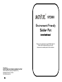
1
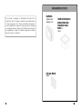
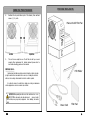
SP2000 Environment Friendly Solder Pot Instruction Manual Thank you for purchasing the Aoyue SP2000 Solder Pot. Please read the manual before using the unit. Keep manual in accessible place for future reference. Manufacturer: AOYUE TONGYI ELECTRONIC EQUIPMENT FACTORY Jishui Industrial Zone, Nantou, Zhongshan City, Guangdong Province, P.R.China http://www.aoyue.com 24 REPLACEMENT PARTS Fan Model# This manual is designed to familiarize and instruct the technician with the proper operation and maintenance of the equipment. The “Care and Safety Precautions” section explains the hazards of using any type of soldering or reworking device. Please read carefully and observe the guidelines in order to maximize usage and minimize the risk of injury or accidents . 1025X86.220V 1025X86.110V Crucible with integrated heating element and Temperature sensor Model # 103411 Filter pad Model# 3055D 2 23 BASIC TROUBLESHOOTING GUIDE PROBLEM 4: THE TEMPERATURE ADJUSTMENT KNOB IS NOT WORKING Description: Turning of the temperature setting knob does not alter the display or show the set temperature level nor does the set temperature level changes with the turn of the knob. CAUSE & SOLUTION: The temperature knob may be damaged and needs to be replaced. Have the unit serviced by a certified technician. PROBLEM 5: DISPLAY SHOWS UNRECOGNIZABLE CHARACTERS SOLUTION: Turn on the main power switch Off and then On again , if the problem persists have the unit serviced by a qualified technician. TABLE OF CONTENTS Product Description …………………………………… 4 Package Inclusion …………………………………… 5 Specifications …………………………………… 6 Functions and Features ……………………………… 7 Safety Precautions …………………………………… 8 Control Panel Guide …………………………………… 9 Operating Guidelines …….…...………….………… 10 — 12 Initial Procedures PROBLEM 6: OTHER PROBLEMS NOT MENTIONED IN THIS DOCUMENT Working with the solder pot SOLUTION: Please bring the unit to a certified service station. Dip soldering Tinning Care and Maintenance ……………………………. 13 — 20 Replacing filter pad Replacing Fan Removing heating element Attaching heating element Basic Troubleshooting Guide ……………………… 21 — 22 Replacement Parts ……….……………………………. 22 23 3 PRODUCT DESCRIPTION BASIC TROUBLESHOOTING GUIDE The Aoyue SP2000 solder pot is a highly durable general purpose industrial solder pot specially made for leadfree applications. PROBLEM 1: THE UNIT HAS NO POWER 1. Check if the unit is switched ON. 2. Check the fuse. Replace with the same type if fuse is blown. 3. Check the power cord and make sure there are no disconnections. 4. Verify that the unit is properly connected to the power source. It has a patented environment friendly design that efficiently filter solder fumes while minimizing unwanted residue. Its ceramic crucible is made of highly durable material that is well suited for lead free processes . While at the same time decreases resi due due to its non metallic composition. The poisonous fumes generated during the soldering are quickly exhaust and filtered away thus significantly reducing byproducts of the soldering process. A microprocessor controlled heater ensures precise temperature regulation ensuring protection from heat damage to components and overheating. Finally, the unique, innovative design with bright digital display provides precision, safety, and ease of use to match all soldering re quirements. PROBLEM 2: TEMPERATURE DISPLAYS BLINKING OFF Description: Upon switching on the unit the display momentarily shows the set temperature then switches to display a blinking OFF. CAUSE & SOLUTION: The thermal sensor may be broken or connection is loose, if unit has been recently opened for servicing, it is most probably a loose connection. Reattach the sensor connector securely . PROBLEM 3: TEMPERATURE IS NOT INCREASING Description: Actual temperature reading is not increasing or de creasing based on desired level. A constant display of relatively low temperature reading on the display panel. CAUSE & SOLUTION: The thermal sensor may be shorted or Heating element is dam aged , if unit has been recently opened double check the wires for loose connection or short. The heating element may be broken and needs to be replaced. Refer to care and maintenance section of this booklet for instruction on how to replace heating element and connection issues. 4 21 CARE AND MAINTENANCE Aoyue 936 规格 8. PACKAGE INCLUSION Reattach the top and bottom part of the chassis, then reattach screws I , J, K, and L. ao y ue SP2 000 S o ld e Left View 9. Main unit with Filter Fan r po t Right View The unit is now ready for use. If unit fails to start up or work properly after replacement of heating element please refer to our trouble shooting guides on this manual. Additional notes: PCB Holder Hardened and cold solder may slide out entirely from the crucible when sub‐ jecting the unit to tilts or movements. This is one way of cleaning the crucible of solder, or when a change from standard to lead free solder is required. It is advised to remove the solder before doing any servicing or maintenance on the equipments so as not to encounter any accidents. IMPORTANT:When pouring hot solder out of the crucible use heat resis‐ tant gloves to tilt the entire unit to the side until a steady stream of solder flows out. Always use proper safety equipments when handling hot molten solder. Power Cord 20 Filter Pad 5 SPECIFICATION SPECIFICATION CARESPECIFICATION AND MAINTENANCE 5. MAIN STATION Power Input : Station Dimensions: available in 110V / 220V 265(w) x 180(d) x 220 (h) mm Weight: 3.8 Kg Power: 600W Temperature Range: Heating Element: Time to melt full pot 480°C: Capacity: Insert the crucible with integrated heating element module back into the main top chassis. 200°C 480°C Band Style Heating Element 20 minutes Heat resistant pads 6. 7. Attach screws M, N, O ,P, and grounding plate as shown above. Reattach the heating elements wires to the connecting grid, in sert the tip of the heating element wires as shown below and retighten the screws to ensure connection. Heating element wires Connecting grid 3Kgs Crucible internal dimension: 77(w) x 77(d) x 60 (h) mm Crucible external dimension: 104(w) x 104(d) x 70(h) mm Bare metallic contacts Insert the heating elements wire’s tip into the connecting grid then retighten this two screws. Reattach the Tempera ture sensor connector to the main PCB Heater Wires Connecting grid 6 Retighten screws to ensure connection Heater Wires Temperature Sensor Wires 19 FUNCTIONS FEATURES Aoyue and 936 规格 CARE AND MAINTENANCE B. Attaching the new Crucible w/heating element 1. Prepare the new crucible with integrated heating element. Take the new crucible with integrated heating element out of its pack aging and ensure that all wires are connected firmly at the body of the crucible. 2. Slide the crucible back into the crucible dock 3. Fasten tightly screws to hold the crucible in a firm grip. ● Microprocessorcontrolled ESD safe equipment. ● Environmentally friendly system combining smoke filter and sol der pot in one sophisticated package. ● Fasten screws tightly Digital display of set and actual air temperature, with knob type control for precision and ease of use. ● Low residue crucible ensures a pure solder. ● The crucible is made of highly durable ceramic which can with stand temperatures of over 400°C. ● 4. Pass the Temperature wire thru the hole located at the bottom part of the top chassis, and the Temperature sensor wire thru hole lo cated at each side. Rearrange the heat resistant pads so that the crucible with heating element would slide in smoothly. Attach the earth grounding plate back to the center of the crucible. Integrated smoke absorber fan with filter pad to efficiently and effectively absorb and filter harmful fumes. ● Compatibility with lead free process. ● Specially designed casing to prevent spillage. Optional: The bottom plate where the temperature sensor wires passes thru may be removed for easy insertion of crucible and heat resistant pads. Reattach this plate after the heat resistant pads are properly inserted. Note: The Heating element wires are thicker than the temperature sensor wires and are covered in flexible ceramic beads. The temperature sensor wires have a connecting head which can easily be attached on to the main board. 2 1 3 Pass Heating element wires thru these holes For 220V pass thru hole 1 &2 For 110V pass thru hole 1 & 3 Pass Temperature sensor wires thru this hole 18 7 SAFETY PRECAUTIONS CAUTION: Improper usage can cause serious injury to personnel and/or damage to equipment and work area. For your own safety, please observe the following precautions. ● Check each component after opening the package to make sure ● everything is in good condition. If there are any suspected dam age, do not use the item and report the issue to your vendor. Turn OFF the power switch and unplug the device from the ● power source when moving the device from one place to another. Do not strike or subject the main unit (and all its components) to ● physical shock. Handle with care. CARE AND MAINTENANCE 6. Loosen the screws on the sides of the crucible dock . This would re lease the grip of the crucible dock on the crucible. 7. Loosen the screws on the crucible clamp. Loosen these screws to separate the crucible with heating element from the crucible dock Loosen these screw to release the crucible clamp from the crucible Crucible dock Never drop or sharply jolt the unit. Contains delicate parts that may break if the unit is dropped. ● Make sure the equipment is always grounded. Always connect ● power to a grounded receptacle. Temperature may reach as high as 480°C when switched ON. Do not use the device near flammable gases, paper and other flamma ble materials. Do not touch heated parts, which can cause severe burns. Do not touch metallic parts near the tip. ● Disconnect the plug from the power source if the unit will not be used for a long period. Turn off power during breaks, if possible. ● Separated crucible and crucible dock The Crucible dock can be expanded a little to allow enough room to Use only genuine replacement parts. extract the crucible/crucible clamp. Turn off and let the unit cool down before replacing any part. After which the crucible clamp can be detached from the crucible. ● Soldering process produces smoke, use on well ventilated places. ● Do not alter the unit in any manner. ● Do not operate near inflammable, flammable and combustible ● material and chemicals. Use proper safety procedures when handling equipments of ex WARNING: If heating element is found to be faulty do not attach to tremely hot temperatures. the unit. Replace crucible with a new and working heating element. 8 Crucible with integrated Temperature sensor and Heating element 17 CARE AND MAINTENANCE 3. CONTROL PANEL GUIDE 焊铁头的维护和使用 Aoyue 936 规格 Loosen screw on the grid connector to detach the heater wires. Note: Detach the two heater wires, and temperature sensor connector located at the back of the control board. Remove screws M , N , O , P, and the earth grounding plate at the center of the crucible. Then care fully pull out the crucible. 5. The crucible together with the heating element, thermal sensor Loosen Temperature sensor connector Heater Wires screw and crucible dock would come out in one piece, leaving the heat resis tant pads inside the chassis. SP2000 4. Heater Wires Solder pot Removing screw M,N,O,P and Grounding Plate M N O Grounding plate P Pulling up top part to expose the crucible clamp and heat resis‐ tant pad. Crucible w/Heating element LEGEND: 1 — Digital temperature display 2 — Temperature Adjustment knob 3 — Smoke absorption switch 4 — Main power switch IMPORTANT REMINDERS: 1.Make sure the equipment is placed on a flat stable heat re sistant surface. 2.Ensure all function switches are OFF prior to plugging in. 3.Ensure all terminal connections are properly secured. Heat resistant pads 16 9 CARE AND MAINTENANCE Aoyue 936 规格 OPERATING GUIDELINES SPECIFICATION Aoyue 936A 规格 NOTE: Please refer to the CONTROL PANEL GUIDE page for buttons and display panel directory. I. INITIAL PROCEDURES 1. Plug the device to the main power source using the power cord pro vided in the package. 2. For empty solder pots, turn on the main power switch(“4” from the panel) to start preheating crucible but make sure that the smoke filtering switch is turned off (“3” from the panel). 3. The digital display (“1” from the panel) will momentarily show the current set temperature then changes to display the actual tem perature of the solder pot. 4. Turn the temperature adjustment knob (“2” from the panel) to the desired setting (recommended is 400° C) and wait for 1520 min utes required preheating time. 5. After preheating, turn ON the smoke filtering function (“3” from the panel) and put in about 200 grams of solder wire inside the cruci ble to melt. 6. When solder wires have molten, you can now put in Solder bars to melt and fill up the Solder Pot. You may opt to reset temperature setting at this point to your desired temperature. Replacing the heating element with crucible and sensor In cases where the heating element has been worn out, the heat ing element/ Crucible may be replaced as follows: A. Removing the old heating element with crucible 1. Remove screws I , J , K , and L. These are located at each sides of the bottom chassis. This will enable us to lift up the top part of the unit. Left View 2. Right View Detach the bottom part of the unit as shown. Be careful not to pull too hard on the top and bottom part of the chassis so as not to damage the wires attached to both sides. IMPORTANT: Take caution on solid solder bars placed inside the crucible, ensure that the solid solder bars will not flip over when it has began to melt which may cause serious injury. Grid connector 10 Loosen screws 15 OPERATING GUIDELINES Aoyue 936 规格 规格 CARESPECIFICATION AND MAINTENANCE 4. Remove the wire mesh and filter pad from the exhaust module. 5. Clean the filter pad or replace it with a new one , place filter pad back into the exhaust module . 6. Secure the filter pad by fitting the wire mesh on top of the filter pad. 7. Replace the exhaust module back into the main unit attach the fan guard and exhaust module securely with screws A, B , C and D (fig. 1 page 13). Replacing the Fan 1. Follow steps 13 of “replacing/cleaning the filter pad” 2. Remove Screws E, F, G, and H as shown. E F Detach the fan’s power connec G 3. tor from the main unit (note: the bot tom chassis may need to be removed H to reach the fan’s other wire see “ re placing the heating element guide for detaching bottom part”). 4. Pull out the Fan. 5. Attach the new fan’s power wires to the main unit. 6. Insert the fan back into the main unit. Reattach Screws E,F,G,H. 7. Reinsert the exhaust module back into the main unit and attach the fan guard and exhaust module se curely with screws A, B , C and D (fig.1 II Working with the solder pot A. For dip soldering printed circuit boards: ● Prepare the PCB to be soldered. Insert all thru hole compo ● nents into the printed circuit board. Use a tong to hold the PCB and briefly dip the underside of ● the PCB into the solder pot. Smoke generated from the process will then be quickly filtered ● thru the filter pad. Continue dip soldering PCBs. ● When all the PCB are soldered. Turn off the smoke absorption switch and then switch off the main power. B. For tinning solder tips, stranded wires and pretinning small electrical parts: ● Prepare the items to be tinned. Ensure items are clean and ● free from unwanted dirt or oil. Use tweezers or pliers to hold small components and briefly dip the tip of the components into the solder pot. ● Smoke generated from the process will then be quickly filtered thru the filter pad. ● Continue tinning items. ● When all the work is finished. Turn off the smoke absorption switch and then switch off the main power. WARNING: Contents of the solder pot can still be very hot for sev‐ eral hours after usage, extreme caution should be followed when handling for storage or placement. page 13). 14 11 CARE AND MAINTENANCE Aoyue 936 规格 OPERATING GUIDELINES SPECIFICATION 保养 III. Illustrations Replacing the filter pad Filters should be cleaned and replaced regularly to avoid dirt which can clog the air passage. More importantly, this will also effectively clean the toxic fumes produced during soldering process. ● Before dipping into the sol der pot Replacing/ cleaning the filter pad 1. Turn off the unit and unplug from the electrical source. Let the equipment cool for several hours until all solder has hardened and entire unit is cool to touch before doing any servicing to the unit. WARNING: Contents of the solder pot can still be molten even though the upper layers seems to have hardened, it is best to leave the soldering pot to cool for 8 hours. 2. During dip soldering Fumes are quickly filtered ● ● ● ● ● 12 After dip soldering Fumes are still being fil tered Board is ready for use Remove screws A B C and D as shown below. Fig.1 Detach screws A,B,C,D 3. Remove the Fan guard and pull out the exhaust module as shown above. 13