1
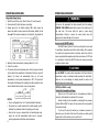
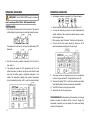
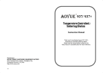
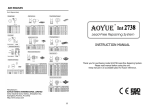
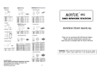
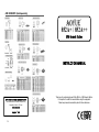
AIR NOZZLES* (Sold Separately) 852A+ / 852A++ SMD Rework Station INSTRUCTION MANUAL AOYUE TONGYI ELECTRONIC EQUIPMENT FACTORY Jishui Industrial Zone, Nantou, Zhongshan City, Guangdong Province, P.R.China www.aoyue.com Copyright © 2007 20 Thank you for purchasing Aoyue 852A+/852A++ SMD Rework Station. It is important to read the manual before using the equipment. Please keep manual in accessible place for future reference. BASIC TROUBLESHOOTING GUIDE This manual is designed to familiarize the user with the proper operation and maintenance of the equipment. The “Care and Safety Precautions” section explains the hazards of using any type of electronic device. Please read carefully and observe the guidelines in order to maximize usage and minimize the risk of injury or accidents. PROBLEM 6: THE UNIT IS VERY NOISY SOLUTION: Make sure the screw has been removed from the center of the base of main unit. Remove if otherwise. PROBLEM 7: THE UNIT IS VIBRATING TOO MUCH Check if the 4 screws that hold the pump in place are properly and tightly connected. Unplug the system from the main power source before opening the case to check the internal settings. PROBLEM 8: DISPLAY AND OTHER DEVICE OPERATION ISSUES SOLUTION: Try to press the “Reset” button on the device. Note that resetting the device will also reset all previously defined configurations. PROBLEM 9: FOR 852A++ ONLY; AIR PRESSURE DROPS WHEN USING THE SUCTION PEN DESCRIPTION: The Air pressure drops when using the suction pen and does not recover to its previous height in the air gauge. SOLUTION: Decrease the air pressure level, set air pressure level at about 80. NOTE: (for 852A++ only) Air pressure level may drop a little when the suction pen is picking up ICs. The air pressure level gauge should revert back to its previous state when the IC is released. Blockages in the suction pen’s tube and nozzle may cause the air pressure to drop. Clean the air passage for maximum air pressure capacity regularly. OTHER PROBLEMS NOT MENTIONED: Contact the vendor. 2 19 BASIC TROUBLESHOOTING GUIDE PROBLEM 4: BANNER OR PRODUCT NAME IS ALWAYS SCROLLING THE UNIT IS NOT USABLE DESCRIPTION: The product name is just always scrolling from the digital panel, rendering the device unusable. SOLUTION: Try to press “Reset” from the panel. Note that resetting the device will also reset all previously defined configurations. TABLE OF CONTENTS PRODUCT DESCRIPTION ………………………….. 4 FUNCTIONS & FEATURES ………………………….. 5 PACKAGE INCLUSION …………………………….. 6 SPECIFICATIONS …………………………………… 6 PROBLEM 5: AIR PRESSURE LEVEL IS SIGNIFICANTLY LOW NO MATTER HOW HIGH THE AIRFLOW LEVEL IS CALIBRATED CARE & SAFETY PRECAUTIONS ……………………. 7 PANEL CONTROLS …………………………………. 8 OPERATING GUIDELINES ………………………. 9-14 MAINTENANCE ……………………………….. 15-16 BASIC TROUBLESHOOTING GUIDE ……………17-19 AIR NOZZLES ……………………………………… 20 CASE 1: Check the mains voltage (AC power source). If the voltage level falls significantly low, about 1520% lower than the standard, there will also be a noticeable drop in the air pressure level. SOLUTION: Please refer to your local power service provider. CASE 2: The microcontroller might have detected the operating frequency incorrectly. The user will notice that airflow level is weaker compared to the displayed value. SOLUTION: Try to press the “Reset” button on the panel and let the device redetect the proper operating frequency. Note that resetting the device will also reset all previously defined configurations. 18 3 PRODUCT DESCRIPTION The Aoyue 852A + / 852A ++ SMD Rework Station is a reworking tool designed to remove and/or repair surface mounted devices such as SOIC, CHIP, QFP, BLCC, BGA, and so on. It is made to repair systems without potentially harming or damaging components by actual or direct contact. One of the key features of this product is the builtin sleep mode with timer functionality. This allows the device to cool down temporarily after a predefined time set by the user with 5 minutes as the default. The sleep mode function will be activated if the hot air gun is docked on the BASIC TROUBLESHOOTING GUIDE PROBLEM 1: THE UNIT HAS NO POWER 1. Check if the unit is switched ON. 2. Check the fuse. Replace with the same type if fuse is blown. 3. Check the power cord and make sure there are no disconnections. 4. Verify that the unit is properly connected to the power source. PROBLEM 2: TEMPERATURE DISPLAY IS ABOVE 500 o C DESCRIPTION: Constant display of above 500 o C temperature from the panel then displays a blinking “OFF” on both sides of the panel after a few minutes. handle and remained idle for 5 minutes. Once the hot air gun is released from the handle during sleep, the unit will automatically switch back to previous working temperature and airflow level conditions without the need for manual intervention. SOLUTION: The thermal sensor may be broken and needs to be replaced. PROBLEM 3: ACTUAL AIR TEMPERATURE IS NOT INCREASING DESCRIPTION: Actual temperature reading is not increasing or decreasing based on desired level. The panel will then display a blinking “OFF” on both sides afterwards. SOLUTION: The heating element may be broken and needs to be replaced, or the thermal sensor could be shorted. 4 17 MAINTENANCE REPLACING THE HEATING ELEMENT The heating element is found at the middle part of the hot air gun. The normal life of a heating element is 1 year under normal operating conditions. Steps: 1. Loosen the 3 screws that secure the handle. 2. Slide off the plastic tube. 3. Disconnect the ground wire sleeve. 4. Inside the pipe, the quartz glass and heat insulation is installed. 5. Peel of the protection tube covering the thermal sensor wires, unsolder the wires and detach from the base. 6. Loosen the clip securing the heating element to the base of the handpiece and slide out the heating element. 7. Insert new heating element and reconnect the thermal sensor wires, use heatshrinktubes to avoid shorting of thermal sensor. FUNCTIONS and FEATURES ● Micro processorcontrolled ESD safe unit ● Fast heating response ● Easytoadjust temperature and airflow control with digital display ● Builtin temperature sensor that aids in providing stable ● (temperature) measurements Builtin thermal protector ● Wide range of operating temperature and airflow level selection ● Integrated airflow gauge for precise airflow level adjustment ● Unique sleep mode with timer functionality ● Automatic cooling functionality for safety and added protection ● Compatibility with various types of air nozzles to meet different repairing requirements Be careful not to rub Heating Element wire. 8. Reconnect the ground wire after replacing the element. 9. Assemble the handle again. 16 5 PACKAGE INCLUSION MAINTENANCE QUANTITY PART DESCRIPTION 1 unit Aoyue 852A+/ 852A++ Main Station with Hot Air Gun 4 pcs Air Nozzles (1124, 1130,1196,1197) 1 pc Z003 Hot Air Gun Holder 1 pc Vacuum Suction Pen 1 pc G001 IC Popper (for 852A++ only) 1 pc Power Cord 1 pc Instruction Manual WARNING All cleaning and/or maintenance should be performed when the equipment is switched off and completely disconnected from the main power source. CHANGING THE FUSE ● Make sure the equipment is completely isolated from the main ● power source before changing the fuse. The fuse of the main unit is located at the back of the ● equipment, right above the power plug connector. Change the blown fuse by unscrewing the fuse holder. ● Replace only with the same fuse type, size, and rating. Use the ● table below as reference. Keep a spare fuse of the same rating for emergency purpose. SPECIFICATIONS Location Station Dimensions Weight Power Input 188 (W) x 127 (L) x 244 (D) mm 3.8 Kg. 500 W Temperature Range 100°C 480°C Pump/Motor Type Air Capacity 6 3A, 220V 5A, 110V Size 5x20mm AC 110220 V / 5060 Hz Power Consumption Heating Element Type Rear Panel Rating Metal Heating Core Diaphragm SpecialPurpose Lathe Pump 23 l/min (Max) SPARE PARTS LIST NUMBER NAME & SPECIFICATION 10094 Hot air gun heating element 30104S Plastic handle of hot air gun S003 Hot air gun complete handle 20932 Hot air gun metal pipe P002 Diaphragm pump 15 OPERATING GUIDELINES 3. Wait for a few seconds while the device is adjusting the actual temperature. The control panel will then display ‘AXXX’ to indicate the actual temperature. Note that actual temperature may vary for ±5% of the defined value. This is normal and should not have any negative impact on reworking. NOTE: The temperature range is between 60 o C and 480 o C. CARE and SAFETY PRECAUTIONS CAUTION Improper usage can cause injury and physical damage. For your own safety, please observe the following precautions. ● Temperature may reach as high as 480°C when turned on. ● Do not use the device near flammable gases, paper and other flammable materials. Do not touch heated parts, which can cause severe burns. Do not touch metallic parts near the tip. Thermal Protector ● Unit is equipped with auto shutoff ability when temperature gets too high and automatically turns on when temperature dropped to a safe level. Handle with Care Airflow Level Setting and Adjustment 1. While the unit is ON and the Hot Air Gun switch set to “Reworking”, press buttons C3 or C4 from the control panel to increase or decrease the airflow level, respectively. 2. The display panel, B2, will show something like ‘EYYY’ while air pressure is being adjusted. 3. Wait for a few seconds until the panel displays ‘FYYY’ indicating Never drop or sharply jolt the unit. Contains delicate parts that may break if unit is dropped. ● Disconnect the plug from the power source if the unit will not be used for a long period. ● Turn off power during breaks, if possible. Use only genuine replacement parts. ● Turn off power and let unit cool before replacing parts. The unit may produce a small amount of smoke and unusual odor during first usage. This is normal and should not yield any negative result when reworking. that actual airflow level has been reached. ● Soldering process produces smoke, use on well ventilated place. ● Do not alter unit, specifically the internal circuitry, in any manner. NOTE: The airflow level range is between 6 and 99. 14 7 PANEL CONTROLS OPERATING GUIDELINES Manual Operating Frequency Selection The SMD Rework Station has already the capability of auto selecting the frequency based on the input power. However, in rare very cases, users may want to manually select the operating frequency. The following procedure will instruct you how to do this. Steps: 1. Switch the unit ON (or press “Reset” button, D, from the panel). 2. Press and hold C1 while the banner is scrolling. 3. The display panel, B1, will initially indicate ‘60’, which means the device is currently operating at 60 Hz of frequency. For 852A++ only Suction pen receptacle 5. Press C2 to confirm. The system will resume automatically. LEGEND: 8 4. Use buttons C3 and C4 to switch between 50 Hz and 60 Hz. A B1 B2 C1 C2 C3 C4 Product Name Temperature Meter Airflow Level Meter Temperature Control (Up) Temperature Control (Down) Airflow Control (Up) Airflow Control (Down) D E F Reset Button Hot Air Output Hot Air Gun Switch G Airflow Gauge H I Power Switch Temperature Adjustment Indicator Temperature Setting and Adjustment 1. While the unit is ON and the Hot Air Gun switch set to “Reworking”, press buttons C1 or C2 from the control panel to increase or decrease the temperature, respectively. 2. The display panel, B1, will show something like ‘bXXX’ while the temperature is being adjusted. You will also notice that a red light (“I” from control panel) is blinking from the panel. This is to indicate that the system is trying to reach or maintain the desired temperature level. 13 OPERATING GUIDELINES Sleep Mode Timer SetUp 1. Switch the unit ON (or press “Reset” button, D, from the panel). 2. Press and hold C3 while the banner is scrolling. 3. Display panel, B2, will initially indicate ‘L05’, which means the device will switch to sleep mode after 5 minutes (default) of idle time and if the nozzle is docked on the handle for the duration of OPERATING GUIDELINES WARNING As soon as the equipment has been removed from the package, REMOVE THE SCREW located at the center of the bottom part of the main unit. This screw holds the pump in place during transportation. Failing to remove the screw before using the equipment can cause damage to the system. How to use the RESET button? The RESET button (button D from the control panel) can be used to reconfigure temperature and airflow level settings. Once pressed, the system will temporarily switch to standby mode then start the device using default temperature and airflow level values of 100 o C and 51, respectively. Pressing the RESET button also removes previously 4. Adjust the time before sleep by pressing buttons C1 or C2. 5. Press C4 to confirm. 6. The device will start counting down when the hot air gun is docked on the handle. Once countdown is finished and the hot air gun still docked, the device will automatically blow air (at room temperature) to bring down temperature to 90 o C. The panel will then display the following after reaching the safe temperature level and to indicate that the device is now in sleep mode. NOTES: ● Time is configurable from 1 to 20 minutes (default 5 minutes). The device has a switch located at the handle (cradle), which ● activates the countdown before the system goes to sleep. Once the hot air gun is released from the handle during sleep ● mode, the unit will automatically switch back to previous 12 working temperature and airflow level parameters. configured system values. CAUTION Do not RESET the system while temperature is still high. Allow the temperature to drop to a minimum before pressing the reset button. Failure to do so can damage the heating element as well as the handle because of excessive heat. NOTE: (for 852A++ only) Suction Pen Assembly and Usage Plug the end of the suction pen to its receptacle and attach a suction tip that matches the particular IC to be used. Suction strength can be increased by increasing the air pressure (buttons C3 and C4). The higher the air pressure the more powerful the suction strength. To pick up ICs using the suction pen, increase air pressure to maximum, cover the hole at the side of the suction pen while gently tapping the tip of the suction pen on top of the IC. 9 OPERATING GUIDELINES IMPORTANT: Use the PANEL CONTROL page for reference. OPERATING GUIDELINES 4. Set desired air pressure by pressing C3 or C4 from the panel. How to use Aoyue 852A + /852A ++ SMD Rework Station? (SMD Reworking) 1. Turn ON the main power switch (H from the panel). The panel will initially display the product name in a scrolling manner like below. The temperature (heat) and air level panel will both display “OFF” afterwards. 5. Adjust hot air gun temperature by pressing buttons C1 or C2. 6. You may start reworking as soon as the actual temperature and desired airflow level have reached the desired values as shown from the display panel. 7. After reworking, select “Cooldown” from the Hot Air Gun switch. 8. This will start the auto cooling function by blowing air at full speed to accelerate cooling down of the hot air gun. 2. Start the hot air gun by selecting“Reworking” from the Hot Air Gun switch, F. 3. The system will operate at 100 o C temperature and 51 on the airflow level meter, by default. You will also notice that the metal ball inside the airflow gauge is positioned somewhere in the middle. The temperature (reading) may overshoot momentarily but will automatically adjust itself to reach the desired (actual) 9. The cooling function will automatically stop once the temperature of the hot air gun reaches 90 o C, as displayed from panel, B1. 10. The panel will display “OFF” on both the temperature and airflow level indicating that the device can already be switched OFF. 11. Turn OFF the device by using the power switch. 12. Unplug the unit from the power source. RECOMMENDATION: When adjusting the temperature, it is strongly advised to increase the airflow level first in order to manage the temperature. Excessive heat may damage the handle and heating element of the equipment. 10 11