1
About the Processor Implementation
2
About the Processor Implementation
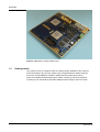
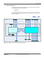
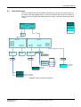
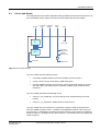
The FPGA image supplied with this Application Note contains an implementation of the
ARM Cortex-M3 r2p0 processor, plus peripherals and bus infrastructure which are
described in section 2.2. The ARM Cortex-M3 processor implements the ARMv7-M
architecture.
2.1
Fixed Configuration
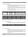
The ARM Cortex-M3 r2p0 processor includes a number of configuration options that may
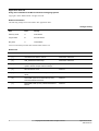
be set when the device is synthesized. Table 1 lists the options chosen for the FPGA
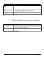
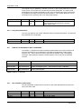
implementation that accompanies this Application Note. Table 2 lists the system
configuration choices that are relevant to this FPGA image.
The “Configuration Name” is the Verilog parameter name used to configure the processor
and is included for reference for processor licencees.
Core Configuration Option
Configuration Name
Value
Comments
Number of Interrupts
NUM_IRQ
32
32 external IRQs
Interrupt Priority
LVL_WIDTH
3
8 levels of interrupt priority (2 )
Memory Protection Unit
MPU_PRESENT
1
MPU present
Debug Level
DEBUG_LVL
3
Full debug with data matching: All debug
functionality is present including data matching
for watchpoint generation.
3
8 Breakpoints
4 Watchpoints
Trace Level
TRACE_LVL
2
Full trace: Cortex-M3 ITM, Cortex-M3 TPIU,
ETM, and DWT triggers and counters are
present.
The TPIU provides 4-bit wide trace on the Mictor
trace connector (“X14”). The trace clock is the
same as the CPU clock.
Register Reset
RESET_ALL_REGS
0
Only essential registers are reset
Debug Interface
JTAG_PRESENT
1
JTAG and Serial Wire debug interfaces
supported by the DAP
Architectural Clock Gating
CLKGATE_PRESENT
0
Clock gating is not implemented in the FPGA
Internal State Observation
OBSERVATION
0
Internal state is not exported
Wake-up Interrupt Controller
WIC_PRESENT
0
The WIC is not implemented in the FPGA
Table 1: Cortex-M3 Processor Configuration
Application Note 218
ARM DAI0218C
Copyright © 2010 ARM Limited. All rights reserved.
3