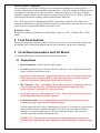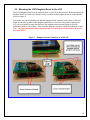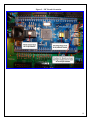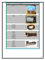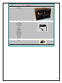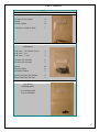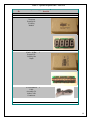
1
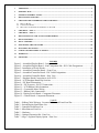
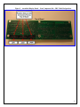
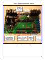
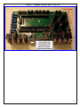
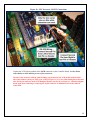
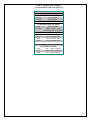
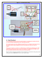
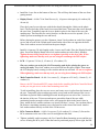
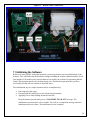
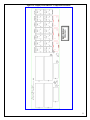
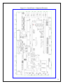
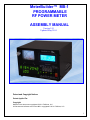
MeterBuilder™ MB-1 PROGRAMMABLE RF POWER METER ASSEMBLY MANUAL Version 1.01 Updated May 2014 Patent and Copyright Notices Patent Applied For Copyright Material in this document copyrighted © 2011 FullWave, LLC. All firmware and software used in the MB-1 copyrighted © 2011 FullWave, LLC. 1 FCC Notice This equipment has been tested and found to comply with the limits for a Class B digital device, pursuant to part 15 of the FCC Rules. These limits are designed to provide reasonable protection against harmful interference in a residential installation. This equipment generates, uses and can radiate radio frequency energy and, if not installed and used in accordance with the instructions, may cause harmful interference to radio communications. However, there is no guarantee that interference will not occur in a particular installation. If this equipment does cause harmful interference to radio or television reception, which can be determined by turning the equipment off and on, the user is encouraged to try to correct the interference by one or more of the following measures: • Reorient or relocate the receiving antenna. • Increase the separation between the equipment and receiver. • Connect the equipment into an outlet on a circuit different from that to which the receiver is connected. • Consult the dealer or an experienced radio/TV technician for help. Changes or modifications to this device not expressly approved by the Manufacturer could void the user's authority to operate this equipment. 2 1 ADDENDUM ........................................................................................................................................................... 4 2 INTRODUCTION................................................................................................................................................... 5 3 GENERAL ASSEMBLY NOTES ......................................................................................................................... 5 4 FRONT PANEL SWITCHES ................................................................................................................................ 7 5 CIRCUIT BOARD ASSEMBLIES AND LCD MODULE.................................................................................. 7 5.1 5.2 5.3 DISPLAY BOARD ................................................................................................................................................... 7 CONTROLLER BOARD.......................................................................................................................................... 10 MOUNTING THE LCD DAUGHTER BOARD TO THE LCD ...................................................................................... 16 6 CHECKOUT – STEP 1 ........................................................................................................................................ 17 7 CHECKOUT – STEP 2 ........................................................................................................................................ 18 8 FRONT PANEL POT AND ANALOG METER WIRING .............................................................................. 22 9 FINAL CHECKOUT ............................................................................................................................................ 24 10 FINAL ASSEMBLY ............................................................................................................................................. 25 11 INITIALIZING THE SOFTWARE .................................................................................................................... 28 12 EXPANSION KIT OPTION ................................................................................................................................ 29 13 LARGE 7-SEGMENT DISPLAY OPTION ....................................................................................................... 29 14 WARRANTY ........................................................................................................................................................ 29 15 PARTS LIST ......................................................................................................................................................... 30 FIGURES Figure 1 – Assembled Display Board – Component Side ................................................................... 8 Figure 2 – Assembled Display Board – Non-Component Side - IDC Cable Designations................. 9 Figure 3 - Installation of Power Diodes ............................................................................................. 11 Figure 4 – Assembled Controller Board – Front View ...................................................................... 13 Figure 5 - Assembled Controller Board – IDC Cable Designations .................................................. 14 Figure 6 – Assembled Controller Board – Rear View ....................................................................... 15 Figure 7 – Daughter Board Connection to 4x20 LCD ....................................................................... 16 Figure 8 – LCD Daughter Board Dip Switches ................................................................................. 17 Figure 9 – PIC Board Orientation ...................................................................................................... 19 Figure 10 – PIC Processor - RS-232 Connections ............................................................................. 20 Figure 11 – LCD Ribbon Cable Orientation ...................................................................................... 21 Figure 12 – Crossneedle Meter Wiring .............................................................................................. 24 Figure 13 – Ribbon Cable Connections ............................................................................................. 28 Figure 14 - Display/Switch Board - Component Placement .............................................................. 51 Figure 15 – Control Board - Component Placement ......................................................................... 52 TABLES Table 1 – Ribbon Cable Wiring to CrossneedleMeter and Front Panel Pot ..................................... 23 Table 2 - Switch/Display Board Parts List ........................................................................................ 31 Table 3 - Controller Board Parts List ................................................................................................. 34 Table 4 - Miscellaneous Parts List ..................................................................................................... 43 Table 5 – Hardware ............................................................................................................................ 47 Table 6 – Optional Expansion Kit - Parts List ................................................................................... 48 Table 7 –Large 7-Segment Display Option - Parts List ..................................................................... 50 3 1 Addendum 1. The R59 value is incorrectly marked as 1K on the silkscreen of the main Controller Board. The correct value is 2.7K. 2. Your MB-1 is shipped with a grey switch for the top right position (Display/Set-Up function) in place of the black switch shown in the figure above. 3. Your MB-1 is shipped with a Blue internal 7-segment LEDs. These, by far, have been the most popular color choice. 4 2 Introduction Thank you for purchasing the MeterBuilder MB-1 Power Meter. This manual describes the steps for assembling the kit. The operating instructions and calibration procedures are described fully in the MB1 User Manual. MB-1 consists of the following assemblies: Display/Switch Board Controller Board High Performance PIC Processor Board (already assembled) 4x20 LCD and LCD driver Daughter Board Crossneedle Analog Meter The PIC processor is a high performance Microchip PIC18F8722 processor mounted on a fully assembled and tested circuit board. This board plugs into the Controller Board in a daughter board arrangement using 40 pin headers. The PIC processor board, the LCD, and LCD driver daughter board contain surface mounted components, but these units are shipped fully assembled. There are no userinstalled surface mount components in this kit. Please check the Parts List before starting assembly. The Parts List starts in Table 2. 3 General Assembly Notes It is recommended that you use a standard 60/40 solder formula and a soldering iron of no more than 30 watts. All components should be mounted flush on the board unless otherwise noted. Because power-to-ground shorts are usually the most difficult to isolate, after installing each group of components such as the switches, the sockets, or connectors, you may want to verify that no shorts have been introduced between ground and the 5 volt bus on the Display Board, or between ground and either of the two 5 volt busses on the Controller Board. If you use this approach, if a short is detected on a power bus, you will only have to backtrack to the last installed group of components to isolate the problem. You can check for shorts by doing a simple continuity check across the 5 volt busses periodically during assembly. If you decide to follow this suggestion, locations where you can perform these checks are given below: Convenient Capacitor Locations to check for power bus shorts: The Display Board has a single 5 volt bus. The Controller Board has two 5 volt busses: +5V, and +5VAUX. Display/Switch Board - Pads of Electrolytic Capacitor C4 Controller Board o +5V – Pads of Electrolytic Capacitor C15 o +5V-AUX – Pads of Electrolytic Capacitor C14 Reducing Assembly Time The capacitors and resistors are the most numerous parts. If you put each resistor value in its own bin or tray (e.g., 33 ohms, 100 ohms, etc), you will find that it is easier to identify an empty slot for a resistor on the PCB, read its value off the silkscreen, and then select that value from the correct bin (as 5 contrasted with installing all of the 33 ohm resistors, installing all of the 100 ohm resistors, etc.). The same applies for the capacitors. One of the 10uf capacitor for the Controller Board is a low profile device Install that electrolytic first as shown in Figure 4. You may want to insert multiple components on the front of the board before soldering them. You will have to bend the leads slightly after inserting each component to hold them in place. Four to six components at a time seems to be a good number. A “circuit board vise”, shown in the picture below, is a handy tool for circuit board assembly. If you are not familiar with these, do a Google search for “Weller circuit board vise”. One more suggestion – after soldering each group of components, before clipping off the excess leads, take a quick look at the soldered connections with a magnifying glass or loop. The fact that the unclipped leads are sticking out makes these newly soldered connections easy to spot for examination. This only adds a few seconds to each group of components and is worth the extra effort. RF Chokes Install all of the RF chokes (L1 – L3) on the Controller Board before installing any other components since this will allow you to check for shorts on both the filtered and non-filtered sides of the power busses (this applies to the Controller Board only). 6 Polarity Sensitive Components Some components, such as the electrolytic capacitors and sound transducer are polarity sensitive. A + symbol is printed on the PCB and should be connected to the + lead of the component. Polarity sensitive components are identified in the “Polarity Sensitive” column in the parts list. (Of course, all diodes, transistors, voltage regulators, and ICs must be oriented correctly as well). For the 1N4001, match the band end of the component (cathode) with the band end on the silkscreen. Note – there are two ways of identifying the polarity on electrolytic capacitors. If the leads on the capacitor are different sizes, the larger lead is the positive lead. Electrolytic capacitors also have a band on the body of the capacitor that identifies the negative lead. Resistance Values Resistors are marked with an R or K to indicate their value (e.g., 47R = 47 ohms, 47K = 47,000 ohms). 4 Front Panel Switches Most of the front panel switches are black. The power switch is red. The four Menu switches and the Display/Set-Up switch (top right switch) are grey so that they can be easily recognized. 5 Circuit Board Assemblies and LCD Module It is recommended that you install components in the following order: 5.1 Display Board Small Components (ceramic capacitors and resistors). IC Sockets (position slot on IC socket as shown on silkscreen – pin 1 tab mounted toward left when viewing the board from the front.) Important – Do not solder the 7-segment LEDS directly to the PCB. You must install the 40 pin sockets even if you do not plan to swap LEDs in the future, since the sockets are required to position the LEDs properly with respect to the bezel. IDC Connectors – Note – on the Display Board, IDC Connectors are mounted on the noncomponent (REAR) side of the PCB with the slots facing toward the TOP of the board (see Figure 2 and Figure 14 - silkscreen layout). Electrolytic Capacitors, observing polarity – Note – The two 10 uF electrolytic capacitors on the Display Board are low profile capacitors. Front Panel Switches - It is recommended that you install the switches last to prevent accidental marring of the switch faces during assembly. You can temporarily apply a piece of masking tape to the face of each switch to keep the switch LEDs inserted until they are soldered into place. If an LED comes out of the switch while handling, it is easily re-inserted but you will have to make sure that the LED is oriented correctly with respect its anode and cathode leads. IMPORTANT - Make sure that you position the switches taking into account the text marking on the switch and the LED configurations of the switch LEDs as shown in Figure 1. 7 The switches will seat in the Display PCB more easily if you let the LEDs float out slightly above the top of the switch while inserting. Once you have fully inserted the contact leads and the two locating tabs on each switch, the LEDs should line up with their mounting holes and you should be able to press them into place. You may find it easier to install the top row of switches first. Note – The PCB pads for the switches are snug intentionally to help maintain the alignment of the switches. However, you may want to apply pressure to the front of each switch when soldering the first two connections to ensure that the switch is fully seated. Do not install the ICs or 7-Segment LEDs on the Display Board at this time. Figure 1 – Assembled Display Board – Component Side (Shown with all components inserted – (Note - Your MB-1 is shipped with a grey switch for the top right position (Display/Set-Up switch) in place of the black switch shown above). 8 Figure 2 – Assembled Display Board – Non-Component Side - IDC Cable Designations 9 5.2 Controller Board Note - the following components are included with the Expansion Kit. If you are not installing the Expansion Kit, leave the corresponding slots on the Controller Board empty: U1, U3: MCP-9922 D-to-A converter IC and associated 14 pin IC sockets (2). U7: 74HCT04 – Hex Inverter IC and associated 14 pin IC socket (1). Install components in the following order: RF chokes L1 –L3. Small Components (ceramic capacitors and resistors, transistors, MCP1541 regulator (TO-92 package - looks like a transistor), and small (1N4001) diodes). You may wish to install the 47 ohm resistor (R48) that is in series with the sound transducer so that it is raised slightly from the board. If you decide that you want to reduce the volume of the sounder, this will allow you to easily clip off the resistor and tack solder in a larger value. Note that R48, a 47 ohm resistor (marked 47R) and R50, a 47K ohm resistor (marked 47K) both get installed on the Controller Board. Be careful not to confuse the two. Relays IC Sockets - (position the slot on the IC sockets as shown on silkscreen – pin 1 tab mounted toward left when viewing the board from the front). If you did not order the Expansion Kit, do not install any IC sockets at the U1, U3, and U7 locations. Sound Transducer - (polarity sensitive). Remove paper covering (or leave it on if you want to operate at reduced volume). All IDC Connectors – Note – on the Controller Board, all of the IDC Connectors are mounted on the component side of the board. IMPORTANT! For the IDC connectors, the slots should be positioned facing toward the FRONT of the board (see Figure 4 and Figure 15 - silkscreen layout). (This does not apply to the right angle IDC connectors mounted on the rear of the board). DB-9 Connector 12 volt DC Power Connector Fuse clips - Insert fuse into fuse clips first before soldering fuse clips to board to ensure proper alignment. Electrolytic Capacitors, observing polarity. Note, one of the electrolytics on the Controller Board is a low profile device (that gets installed under the PIC daughter board – see Figure 4). Install this first. High Current Diodes (1N540x) - Mount these diodes vertically with the cathode face down (toward the board) and the anode face up. Wrap the anode lead back around the body of the diode and connect it to the PCB. The Cathode side of the diode (band on cathode side) gets 10 connected to the circle part of the silkscreen legend as shown below. There are four of these diodes. Make sure that you raise these diodes approximately ¼ inch off the board exposing ¼ inch of lead between the board and the diode. This extra lead length provides some additional heat sinking for the diodes reducing their operating temperature. Figure 3 - Installation of Power Diodes RCA Jacks – Very important! - Be careful to ensure that the RCA jacks are mounted perpendicular to the board and fully seated. Tack solder the diagonal corner pins first and check alignment before soldering the remaining pins. Proper alignment of these connectors is required for the Controller Board to mount properly in the case. 3 Pin Headers – Install both 3 pin headers as shown in Figure 6. Install shorting plugs on each of these headers for the 5 volt connection as shown. These jumpers select either 5 volts or 12 volt power for each of the two external displays. The external display devices that are included with the Expansion kit are powered from 5 volts. 40 Pin Headers - These connect the PIC processor daughter board to the Controller PCB. To ensure proper alignment, first plug the PIC processor board into them two 40 pin headers (6 pins are unused on the ends of each header). The orientation of the processor board is not critical at this point since no power is being applied – you are just using the PIC board for spacing. Mount the daughter board/header assembly by tack soldering the four diagonal corners on the 40 pin headers. Make sure the headers are flush and square with the PCB before soldering the remaining pins. Remove the PIC processor board after all header pins are soldered. Heat Sinks and LM7805 Regulators – Install a small amount of heat sink compound (provided) on the back of each 7805 voltage regulator before attaching it to the heat sink. Install the 7805 to the heat sink with a 4-40 x ¼ screw, lockwasher, and nut using the middle hole on the heat sink. Make sure the 7805 is positioned squarely on the heat sink before tightening the mounting screw since the heat sink/7805 will be soldered to the board as a single assembly. Make sure that the heat sink assemblies are mounted perpendicular to the Controller board. Tack solder the 7805 pins first checking alignment. Then tack solder one of the heat sink tabs while ensuring that the heat sink assembly is mounted squarely on the circuit board and perpendicular to the board’s surface. Finish soldering the heat sink assemblies and 7805 leads. 11 Coupler and Panel Meter Trim Pots – Preset the Panel Meter Trim Pots (single turn pots) at approximately 50% of full travel. This will guarantee a readable output at the Panel Meter output ports during the self test sequence without risk of severely overdriving the internal panel meter or any externally connected analog meters. Preset the Coupler Trim Pots (blue multi-turn pots) to at least 50% of full CW travel (7 ½ turns CW or more). This will guarantee a detectable output during the self test sequence of the coupler ports. (Note that the coupler trim pots have no mechanical stops). Plug in the HCF4069 Hex Inverter IC (U6). This IC is required to operate the Power Relay on the Controller Board during initial checkout. As with all ICs, observe proper positioning of pin 1 on the IC with respect to the socket. (When viewing the board from the front, pin 1 is positioned toward the left of the board for IC’s oriented left-right. Pin 1 is positioned toward the top of the board for IC’s oriented up-down.) Do NOT install the other ICs at this time. Also, do not install the PIC processor board at this time. 12 Figure 4 – Assembled Controller Board – Front View Shown with all components installed 13 Figure 5 - Assembled Controller Board – IDC Cable Designations 14 Figure 6 – Assembled Controller Board – Rear View Shown with all components installed 15 5.3 Mounting the LCD Daughter Board to the LCD The LCD Daughter Board must be soldered to the 4x20 LCD as shown below. Before mounting the daughter board, first make sure that the two dip switches on the daughter board are in the position shown in Figure 8. Tack solder one pin first making sure that the daughter board is parallel to the main LCD board. Make sure no pins or paths on the daughter board touch or are close to the paths or pins on the LCD. (It is acceptable to angle the bottom of the daughter board upward slightly to provide additional clearance if necessary.) After assuring adequate clearance, solder the remaining 15 pins. Note – the Demo board and other components that come packaged with the 4x20 LCD are not used with MB-1. Figure 7 – Daughter Board Connection to 4x20 LCD 16 Figure 8 – LCD Daughter Board Dip Switches 6 Checkout – Step 1 Connect a 10 pin IDC ribbon cable assembly between the JPWR Connector on the Display Board and the JPWR Connector on the Controller Board. Also connect a 14 pin IDC ribbon cable assembly between the JLED Connector on the Display Board and the JLED Connector on the Controller Board. Make sure the fuse is installed. Connect the 12 volt DC supply to the power connector (barrel connector) on the Controller Board. You must operate the power relay on the Controller Board to check for power on the two 5 volt Controller Board busses. Do this by pressing the POWER button (bottom right button) on the Display/Switch Board. (The above ribbon cable connections route power from the Controller Board to the Display Board, and also connect the switch contacts from the PWR switch on the Display Board to the power relay circuit on the Controller Board through leads ON-OFF-SW1 and ON-OFF-SW2.) 17 Each push of the Power switch should toggle the power relay (RLY1) on/off. If you do not hear the relay click (and see the LED on the PWR switch light up), troubleshoot the power-on circuit, which consists of a simple flip flop (4069 IC) and the Power Switch. Once the power relay is operated, verify 5 volts on the display board, and 5 volts on each of the two 5 volt busses (+5V and +5V–AUX) on the Controller board. The measured voltages should be within .1 volts of 5 volts. The following are convenient locations to check for 5 volt power: Display/Switch Board - Pads of Electrolytic Capacitor C4 Controller Board o +5V Bus – Pads of Electrolytic Capacitor C15 o +5V-AUX Bus – Pads of Electrolytic Capacitor C14 If you are not reading the correct voltage, do not proceed until you troubleshoot the voltage problem. The Circuit Description document contains the complete schematic of the meter. 7 Checkout – Step 2 If the 5 volt busses check out, remove the power cable from the Controller Board barrel connector and remove the interconnecting ribbon cables. Then install the remaining components as described below. Display Board: Insert the two 7219/7221 IC drivers, positioning pin 1 on each IC toward the left side of the board when viewing the board from the front in its normal orientation. Install the 7-Segnent LEDs in the 40 pin sockets on the Display Board. Position each 7-segment LED so that the decimal point is oriented toward the bottom of the board. Controller Board: Insert all remaining ICs on the Controller Board, making sure to properly position pin 1. (When viewing the board from the front, pin1 is positioned toward the left side of the board for IC’s oriented left-right. Pin 1 is positioned toward the top of the board for IC’s oriented up-down.) Mount the processor daughter board as shown below in Figure 9. Make sure to observe orientation of the processor board as well as positioning of the board into the proper slots on the 40 pin headers. (6 pins on each 40 pin header are unused by the PIC processor board on the side of the board opposite to the heat sinks). Install the two jumper wires from the PIC processor daughter board to the 40 pin header pins as shown in Figure 10 (the colors of the jumper leads may differ from those shown in the photo. Just make sure to interconnect the leads as shown. These leads connect the RS232 transmit and receive signals from the PIC daughter board to the DB-9 connector for communication to a PC. 18 Figure 9 – PIC Board Orientation 19 Figure 10 – PIC Processor - RS-232 Connections Connect the LCD Display module to the JLCD connector on the Controller Board. Use the ribbon cable that has a white marking on one of the connectors. The side of the connector with the white marking gets mounted on the LCD module with the white side of the connector facing the TOP of the LCD (see Figure 11). Use care when making this connection since the 10 pin connector on the LCD Daughter Board is not keyed. See Figure 11. Hold the daughter board rigid when connecting or removing the 10 pin connector to minimize strain on the soldered connections. 20 Figure 11 – LCD Ribbon Cable Orientation Connect the JPWR, JSW, and JLED IDC connectors on the Controller Board to the corresponding IDC connectors on the Switch/Display Board using the 10 pin and 14 pin grey ribbon cable assemblies. (The shorter 10 pin cable assemblies should be used. The longer 10 pin cable assemblies, if provided, are part of the Expansion Kit and are used to connect the hi-visibility external displays.) Plug a 12 V DC source into the Controller Board power connector. Make sure to observe polarity (center pin is +). While the majority of the circuitry in the MB-1 is protected against reverse polarity, a couple of components used in the soft startup circuit are not, and can be damaged by applying the wrong polarity. Press the Power Switch. The Power Relay should operate and a startup message should appear on the LCD followed by the normal LCD display. If you do not see the startup message, verify 5 volts on the Display Board and Controller Board power busses. If power is present, verify power at each of the ICs, the LCD, and the PIC processor board. If you hear a two second beep during power-up, read the paragraph below. (It is normal for only the top 7-segment modules to be on at this point.) Two Second Beep Fault Indication This section applies only if you hear a two second beep during power up. 21 During power up, a number of self-tests are performed. One of these tests checks the serial I/O bus between the processor and the peripherals (the Serial Peripheral Interface (SPI) bus) by doing a handshake between the PIC processor and the LCD module. If this check fails, first check that the ribbon cable that connects the main controller board to the LCD. An unconnected or improperly connected LCD cable will cause the 2 second beep. If the cable is connected properly, this indicates that a board problem exists that is preventing the SPI bus leads from propagating to or from the processor. The leads that are involved are the SPIOUT, SPI-IN, and SPI-CLK leads, as well as the buffered signals derived to and from these leads (see schematic). Check that pulses are appearing on the SPI-OUT and SPI-CLK leads at the PIC daughter board as well as the buffered leads. Also determine if pulses are present at the SPI-IN lead at the at the PIC daughter board. If you find a problem with these leads, examine the related traces including the derived buffer signals for bad solder connections or solder bridges. Also examine the IC that buffers these signals. 8 Front Panel Pot and Analog Meter Wiring Remove the previously connected power connection and ribbon cable assemblies. One of the pre-assembled ribbon cables uses a colored ribbon cable. Remove a small amount of insulation from all 10 leads from the side with no connector. Connect these leads to the crossneedle meter and front panel potentiometer as shown in Table 1 and Figure 12. Note – the brown and yellow leads of the ribbon cable are connected to ground on the Controller Board. These leads get connected to the FWD and REFL coil common leads of the crossneedle meter as well as to the cathode side of all three illumination LEDs on the crossneedle meter housing. (The left lead from each LED is the cathode lead when looking at the meter from the rear housing side). The anode lead of each LED gets wired to its own ribbon cable lead as shown in the table below and in Figure 12. 22 Table 1 – Ribbon Cable Wiring to CrossneedleMeter and Front Panel Pot Wire Color Connection Crossneedle FWD coil Wiring Brown FWD Needle + Orange FWD Needle Crossneedle REFL coil Wiring Red REFL Needle + Yellow REFL Needle – and to cathode side of all LEDs Crossneedle LED Wiring Purple LED 1 (Anode side) Blue LED 2 (Anode side) Green LED 3 (Anode side) Black Grey White Potentiometer Wiring Pot – Front Terminal Pot – Center Terminal Pot – Rear Terminal 23 Figure 12 – Crossneedle Meter Wiring 9 Final Checkout It is recommended that final checkout be performed prior to mounting the circuit boards in the case. This will make troubleshooting easier if a problem is detected. For normal operation, the white pushbutton on the PIC processor daughter board must be in the UP position and the white shorting pins on the PIC board must be connected as shown in Figure 9. When power is turned on, you will see one illuminated green LED and one illuminated red LED on the PIC board when this switch is in the correct position. Two illuminated red LEDS on the PIC board indicate that this switch is in the incorrect (down) position. Plug the Connector end of the colored ribbon cable assembly that is connected to the front panel pot and analog meter into the JMTR/POT ICD Jack on the Controller Board. 24 Using the ribbon cable assembly with the white marking on one of the end connectors, connect the LCD Display module to the JLCD ICD connector on the Controller Board maintaining the orientation of the white marking as shown in Figure 11 (white marking faces toward top of LCD). Please double check this. Connect the JSW, JLED, and JPWR connectors on the Controller Board to the corresponding connectors on the Switch/Display Board using the appropriate size 10 pin and 14 pin (grey) ribbon cable assemblies. The Jack designations appear on the silkscreen of both the Display Board and Controller Board. Isolate all subassemblies to prevent shorts while testing. The pink (static control) bubble wrap is useful for this. Connect the 12 volt power cable to the power barrel connector on the Controller PCB. Power up the unit with the front panel Power Switch (bottom right switch). Press the UP or DOWN menu buttons on the front panel until the SELF_TEST Menu is displayed on the bottom line (line 4) of the LCD as shown below. Then push the leftmost menu button (short press of M1) to start the self test. The self test sequence is described fully in the MB-1 User Manual. If any failures are detected, the self test procedure that failed together with the schematics and Circuit Description should aid you in localizing the problem. You will also find additional troubleshooting procedures here. Self Test Menu --- ----- -- ----- --- ----- -- ----- --- ------ ----SELF-TST-START - - - 10 Final Assembly Important Note: Be careful when tightening the nuts to not over tighten. Avoid contacting the circuit board surface with any tools. Remove the power cable. If your DB-9 connector came equipped with standoffs, remove them from the DB-9 connector. You will find it easier to mount the boards in the case if you first unplug the ribbon cables and reconnect them after the circuit boards are secured to the case. Just make sure to connect them to the correct IDC jacks. Before installing any of the boards, sand the four areas on the inside of the case front where spacers from the Display Board will contact the case to ensure good grounding. Also sand the five areas on the inside of the case bottom where the spacers from the Controller Board will contact the case. 25 Mount the boards and other components to the case using the hardware specified below. Install the 4 case feet on the bottom of the case. This will keep the bottom of the case form getting marred. Display Board - #4-40x 7/8 in Panel Screws (4), #4 spacers 3/8 length (6), #4 washers(18), #4 nuts (6) Place the 4 panel screws (the ones with the hex heads) through the 4 holes on the plastic bezel. The beveled edge of the bezel faces toward the front). Then insert the screws through the case front. Temporarily tape the 4 screw heads in place to the front of the case with masking tape. Then turn the case on its front face so that the screws face upward. (Use a cloth to prevent scratching the case and bezel). Before placing the spacers over the 6 fasteners, insert 2 lock washers on each of the 4 panel screws and on each of the 2 blind studs located on the side of the case opposite the bezel. These lock washers are used to build out the spacer length. Install 6 #4 spacers (3/8 inch length) on the 4 screws and 2 studs. Place the Display Board in place. Secure the Display Board with a lock washer and nut on each of the 6 fasteners. Tighten the nuts being careful not to over tighten (especially on the bezel side). When tightening, make sure that any tools you are using do not damage the PCB surface. LCD - #2 spacers 5/16 in (4), #2 nuts (4), #2 washers (12). Place two washers on each of the 4 LCD mounting studs before placing the spacer on each of the studs. These lock washers are used to build out the spacer length. Then mount the LCD display board, securing it with a washer and nut on each stud. Do not over tighten. When tightening, make sure that any tools you are using do not damage the PCB surface. Main Controller Board - #4-40x 1 in screws (5), #4 spacers x 5/8 in (5), # 4 nuts (5), #4 washers (5). Remove the PIC Board and RS232 jumper leads before installing the Main Controller Board so that you can gain access to the center mounting screw hole. To aid in installing, place the two rear screws and center screw in place from the bottom of the case. Temporarily place masking tape on the screw heads on the bottom of the case to hold them in position while installing the board. Install spacers on each of the 3 screws in the interior of the case. Tilt screws and spacers toward the front of the case while positioning board at an angle so that screws will engage the holes in the board. Once in place, attach the lock washers and nuts very loosely on these 3 screws. You can then slide in the front two remaining mounting screws and spacers on the front of the board. Attach a lock washer and nut loosely on each of the 2 front screws. RCA Connector Blocks - #4-40x 1 in screws (2), #4 washers (2), #4 nuts (2). Secure the RCA connectors to the rear of the case. Do not tighten at this time. Tighten, gradually, and in sequence, the five Controller Board mounting screws and the two screws securing the RCA jacks. When the board is positioned properly left-to-right, the DB26 9 connector will be centered in its cutout. Do not over tighten. When tightening, make sure that any tools you are using do not come in contact with the PCB surface. Reinstall the previously removed PIC Board and RS232 jumper leads on the Main Controller Board as shown in Figure 10. Panel Meter – 2 Fender washers, #4-40 screws x ¼ in (2), #4 washers (4). Locate the Panel Meter in its cutout. Insert each screw through a fender washer. Then place 2 lock washers on each screw before screwing them to the Panel Meter standoffs. Do not over tighten or the Panel Meter case will crack. Front Panel Potentiometer – 2 nuts, 2 washers. Before inserting the pot, install 1 nut and washer on the pot threads so that the threads from the pot will extend only slightly through the front of the case. Secure the pot with the other washer and nut from the front of the case. Make sure that the wires connected to the pot are positioned toward the bottom of the case to avoid any shorts. Install the knob on the shaft of the front panel pot. If you are installing the chrome knob that comes with the Expansion Kit, use a 1.5 mm hex wrench to tighten the screw. Install handle on rear of case (Expansion Kit only). Carefully reconnect all cables with particular care of the cable that connects the LCD to the main controller board. Make sure the white marking on the ribbon cable end that connects to the LCD faces the top of the case. As shown in the figure below, when viewing the case from the rear, the connector designations on the Switch/Display Board, when read from left to right are: JSW (14 pin) JLED (14 pin) JPWR (10 pin) If you ordered the Expansion Kit, 2 blank RCA male plugs are included. Plug these blanks into the two +5 volt auxiliary power jacks on the rear panel (labeled +5v) to prevent unintentional connections to these jacks. (Note that all ribbon cable assemblies in shipped units are grey except the cable assembly that connects to the front panel pot and internal crossneedle meter to the Controller Board (JMTRPOT)). 27 Figure 13 – Ribbon Cable Connections 11 Initializing the Software Before you can use MB-1 for normal operation, you must perform a one time initialization of the software. This will load in the default meter settings including the coupler calibration tables. It will also load the LCD module with a special character set used by the software for generating the Bar Graph. This operation needs to be performed only once. Perform this operation after you have successfully run the self test routines as described above. The initialization step is a simple operation and is accomplished by: Powering down the meter. Pressing both M1 and M2 keys (two left-most menu buttons). Applying Power while holding in both M1 and M2. Keep the buttons pressed until you see “SYS RESET, PLS WAIT" message. The initialization operation takes a few seconds. You will see a completion message when the initialization process is done. The initialization is now complete. 28 Note that the trim pots for your Panel Meter and Coupler are not yet adjusted. The procedures for making these adjustments are given in the User Manual. Congratulations! Before proceeding, if you have not done so already, first spend a few minutes reading the Programming MB-1 link on the MeterBuilder website. It is essentially a high level summary of the information covered in this walkthrough in the Quick Start Guide in the User’s manual. You then have two options. You can proceed to the Quick Start walkthrough (sections 1 and 2) in the MB-1 User Manual. Or if you want to skip some of the details at this point, jump to the no-nonsense version of the Quick Start Guide authored by AD5X. They are both on the documentation page. 12 Expansion Kit Option The expansion kit option includes a number of accessories. The parts list for the Expansion Kit is shown in Table 6. The Expansion Kit is required if you wish to install additional (external) analog panel meters. It is also required to use the external 7-Segment Display and external Bar Graph module with MB1. The standard MB-1 (without the Expansion kit) is supplied with a pre-programmed 25AA128 (16 KB) external EEProm. The Expansion kit is supplied with a pre-programmed 25AA256 (32KB) external EEProm. If you ordered the optional expansion kit, you will receive the 25AA256 EEProm memory chip only. 13 Large 7-Segment Display Option This option is currently included at no additional cost with the Expansion Kit. It allows you to configure MB-1 to operate with the very large family of SURE Electronics External 7-segment display modules (1.8 inches to 7 inches in height). See: http://stores.ebay.com/Sure-Electronics and search for “Information Boards”. 14 Warranty The original purchaser of MeterBuilder MB-1 Kit is covered by a 12-month, limited warranty from the date of purchase from FullWave, L.L.C. The warranty covers defects in components and materials for one year. The warranty does not cover defects due to improper assembly or components damaged during assembly. The sole obligation of FullWave, L.L.C. under this warranty is to replace defective components within the one year warranty period. Defects attributable to abuse, misuse, improper installation, or accidental damage are not covered by this warranty. Any incidental or consequential damages resulting from any defects in this product are excluded, including damage to other equipment used with the MB-1 Meter. This warranty also does not cover damages or inconvenience resulting from changes or availability in the third-party accessories that the 29 MB-1 meter is capable of operating with. 15 Parts List All Resistors are 1/8 watt unless otherwise specified. 30 Table 2 - Switch/Display Board Parts List Component ID C1, C3 C2, C4 R1, R2 Description Qty .1 uF Capacitor (Marked 104) 2 10 uF Capacitor (Low Profile) (color may vary) 2 10K Resistor 2 Polarity Sensitive Yes (Brown-BlackOrange) R3 1K Resistor 1 (Brown-BlackRed) JPWR 10 Pin ICD Connector 1 JLED, JSW 14 Pin ICD Connector 2 U1,2 MAX7219CNG or MAX7221CNG 2 IC (24 pins) S5,6 24 pin IC socket 2 S1,2,3,4 40 Pin Socket for 7 Segment LEDS 4 31 Component ID LED-16 Description Qty 7-Segment Common Cathode (Blue) 16 SWMENUDOWN Black Front Panel Sw Single LED (Green) 1 Polarity Sensitive Yes Text = “DOWN” SWMENU1 SWMENU4 Grey Front Panel Sw Single LED (Green) 2 Text = “Menu” SWMENU2 SWMENU3 Grey Front Panel Sw Single LED (Yellow) 2 Text = “Menu” SWMENUUP Black Front Panel Sw Dual LED (Red, Yellow) 1 Text = “Up” SW7SEG SWBKUP Black Front Panel Sw Single LED (Green) 4 No Text 32 Component ID Description Qty SWPANMTR SWALARM Black Front Panel Sw Dual LED (Green, Yellow) 2 Polarity Sensitive No Text SWMINMAX SWCOUPLR Black Front Panel Sw Single LED (Yellow) 2 No Text SWPOWER Red Front Panel Sw Single LED (Green) 2 No Text SWDISP Grey Front Panel Sw Single LED (Green) 2 No Text PCB Switch/ Display Circuit Board (Latest version has 6 mounting holes) 1 33 Table 3 - Controller Board Parts List Note – the components listed in red font below are not included if the optional Expansion Kit was not ordered. Component ID Description Qty .1 uF Capacitor (Marked 104) 26 C27 C36 C37 C41 C42 C53 C54 C58 C59 1000pf Capacitor (Marked 102) 9 C34 C35 470pf Capacitor (Marked 471) 2 C43 C44 C45 C46 C47 C48 C49 C50 100pf Capacitor (Marked 101) 8 30pf Capacitor (Marked 300) 5 C1-C11 C13 C16 C17 C19 C21 C22 C24 C28 C32 C33 C39 C40 C52 C55 C57 C23 C25 C26 C29 Polarity Sensitive 34 Component ID Description Qty Polarity Sensitive C38 10 uF Capacitor (Low Profile) (color may vary 1 Yes C12 C14 C15 C18 C20 C31 C51 C56 10 uF Electrolytic Capacitor (Standard Height Profile) (color may vary) 8 Yes CONDC 2.5mm Power Jack 1 D1 – D4 1N540x Diode (Large diodes) 4 Yes D5, D6 1N4001 Diode (Small diodes) 2 Yes C30 Fuse Clips 2 35 Component ID Description Qty Fuse 1.6 amp quick blow Fuse Size: 5mm x 20mm 2 Ext7Seg1 Ext7Seg1 3 pin Header – Supplies 5 volt or 12 volt power to External Display devices 2 Shorting pins for 3 pin headers 2 Header1 Header2 40 Pin Header – Female for PIC Board Installation 2 JCOUP JPM 12 port RCA Jack 2 JHV1 JHV2 10 Pin ICD Connector Right Angle 2 JLCD JMTRPOT JPWR 10 Pin ICD Connector 3 JLED JSW 14 Pin ICD Connector 2 Polarity Sensitive 36 Component ID Description Qty JRS1 DB9 RS232 Connector 1 L1 – L3 RF Choke 3 Piezzo1 Sound Transducer 1 Yes Q1, Q2, Q3 2N4401 Transistor 3 Yes Q4 MCP1541 4.096v Voltage Reference 1 Yes 33 ohm Resistor 11 R22 R25 R42 R54 R56 R60 R62 R64 R65 R66 R69 R48 Polarity Sensitive (Orange- Orange-Black) 47 ohm Resistor 1 (Yellow-Violet-Black) R13 R14 R15 100 ohm Resistor 3 (Brown-Black-Brown) 37 Component ID Description Qty R24 R27 R31 R37 R39 390 ohm Resistor 5 R16 R18 R19 R21 R23 R26 R30 R32 R34 R35 R36 R38 R40 R41 R43 R44 R45 R52 R53 R55 Polarity Sensitive (Orange-White-Brown) 1K ohm Resistor 20 (Brown-Black-Red) R7 R8 R9 R10 R11 R12 R59 2.7K ohm Resistor R49 5.1K ohm Resistor 7 (Red-Violet-Red) 1 (Green-Brown-Red) R17 R20 R28 R33 R51 R47 10K ohm Resistor 5 (Brown-Black-Orange) 24.9K Resistor (not color coded) 1 38 Component ID R50 Description Qty 47K ohm Resistor 1 Polarity Sensitive (Yellow-Violet-Orange) R29 R46 R57 R58 R61 R63 R67 R68 R78 R79 100K ohm Resistor 10 (Brown-Black-Yellow) R70 R71 R72 R73 R74 R75 R76 R77 Coupler Trim Pots 200K 8 R1 R2 R3 R4 R5 R6 Panel Meter Trim Pots 100K 6 RLY1 Power Relay G6RN-1 DC12 1 RLY2 DPDT (Alarm) Relay G5V-2-H1 DC5 1 39 Component ID Description Qty U1, U3, U4 MCP4922 Dual 12 bit D-to-A Converter (14 pins) 1+2 (3 Total) U2, U5 LM-7805 Power Regulator 2 Heat Sink 2 Heat Sink Compound 1 package U6 HCF4069 CMOS Hex Inverter (14 pins) 1 U7 74HCT04 Hex Inverter/Buffer (14 pins) 1 U8 MCP23S17 16 Bit I/O Expander (28 pins) 1 U9 74HCT08 Quad AND gate (14 pins) 1 U10 MCP-6S28 Programmable Gain Amplifier/Multiplexer (16 pins) 1 Polarity Sensitive 40 Component ID Description Qty U11 Pre-Programmed 25AA128 128 K Serial Bus (16 KB) EEPROM (8 pins) 1 Polarity Sensitive or Pre-Programmed 25AA256 256 K Serial Bus (32 KB) EEPROM (included with Expansion Kit) (8 pins) 8 Pin IC socket 1 14 Pin IC socket 3+3 (6 Total) 16 Pin IC socket 1 28 Pin IC socket 1 ET-PIC Stamp Processor Board (Daughter Board) 1 Yes!! 41 Component ID Description Qty Jumper Leads 2 Hookup wire for crossneedle meter connections 1 Polarity Sensitive 42 Table 4 - Miscellaneous Parts List Component ID Description Qty Polarity Sensitive LCD Daughter Board LCD1 4x20 LCD 1 Yes – Position Connector with white marking on ribbon cable facing TOP of LCD 43 Component ID M1 Description Qty Crossneedle Meter 1 MB-HF1 Coupler Polarity Sensitive Yes Yes Shielded RCA Cable for Coupler Connection 10 Lead Ribbon Cable Assembly (Colored Cable) with Connector on one end 1 10 Lead Ribbon Cable Assembly (Grey Cable) with Connectors 1 44 Component ID R100 Description Qty 10 Lead Ribbon Cable Assembly (Grey Cable) with Connectors with white marking for LCD connection 1 14 Lead Ribbon Cable Assemblies (Grey cable) with Connectors 2 4.7K 10 Turn Hi Resolution Pot 1 Knob 1 Bezel PCB Controller Circuit Board Polarity Sensitive 1 1 45 Component ID Description Qty Enclosure 1 12 volt Power cord - 2.5 mm tip (Not included with Expansion Kit, which includes power cube.) 1 Feet 4 Polarity Sensitive 46 Table 5 – Hardware Description Qty #2 Hardware 2 #2 spacer 5/16 in length #2 nuts #2 lock washers 4 4 12 1.5mm hex wrench for knob 1 #4 Hardware 4-40 screw - 7/8 in Panel Screws 4-40 screw - 1 in 4-40 screw - 1/4 in 4 7 4 #4 spacer 3/8 in length #4 spacer 5/8 in length 6 5 #4 nuts #4 lock washers #4 Fender Washers 14 31 2 Large Front Panel Pot Washers Large Front Panel Pot Nuts 2 2 Case Screws including spares (Case shipped with 8 screws installed) 47 Table 6 – Optional Expansion Kit - Parts List Component ID Description Qty 1.5 inch 7-Segment External HiVisibility Module 1 4 Inch - 40 Bar External HiVisibility Bar Graph 1 10 Lead Ribbon Cable Assembly (20 inches) with Connectors 2 Polarity Sensitive 48 Component ID Description Qty Double sided Trim Pot Adjustment tool 1 Polarity Sensitive Chrome Finish Knob U11 Case Handle 1 Blank RCA Plug 2 25AA256 256 K Serial Bus (32 KB) EEPROM. PreProgrammed with Expansion Kit Features 1 49 Table 7 –Large 7-Segment Display Option - Parts List Component ID Description Qty U11 Replacement for 25AA128 Pre-Programmed 25AA256 256 K (32KB) Serial Bus EEPROM. Pre-Programmed with Expansion Kit Option and Large External Display Option 1 Polarity Sensitive Spare Components: The kit is shipped with the following spare components: . 1.6 amp Fuse Choke (The RF chokes will pop if they encounter even a brief short on the output side (as could happen if you plug in IC in upside down), so check for continuity across the chokes if you encounter a problem. Panel Meter Trim Pot Coupler Trimmer Pot Shorting pin for 3 pin headers 2 extra case screws Notes: Some of the External Seven Segment Display Modules and the External Bar Graph modules are packaged with a demo board and a ribbon cable assembly. The 4x20 LCD is may also be packaged with a demo board and a ribbon cable assembly. These demo boards and cable assemblies, if provided, are not used with the kit. 50 Figure 14 - Display/Switch Board - Component Placement 51 Figure 15 – Control Board - Component Placement 52 Notes 53