1
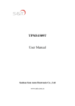
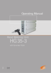
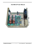
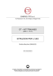
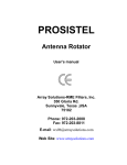
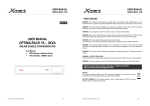
DU 1500 L tuner
USER MANUAL
ARRAY SOLUTIONS
2611 N Belt Line Road - Suite 109
Sunnyvale, TX 75182 USA
1(214) 954-7140 office
1(214) 954-7142 fax
[email protected]
CHAPTER 1
Model DU 1500 Installation
Model DU 1500 L is high power antenna tuner that uses and adjustable reactive network for
matching the unbalanced 50 ohm output impedance of transmitters and transeivers to a variety
of balanced and unbalancedloads.
It is usable over a frequency range of 1.8-30 MHz. Provision is made for selecting one of
three antennas or for bypassing the matching network.
A crossneedle SWR and wattmeter with swithcable 200 and 2000 watt scales and selectable
peak and average power output reading is included.
TRANSMITTER CONNECTION
The DU 1500 L is designed for connection to transmitters having a 50 ohm nominal output
Impedance.
Connect the coaxial output of your transmitter to the SO 239 type INPUT connector on the
rear panel of the tuner with a 50 ohm coaxial cable.
GROUND
Connect your station ground system to the GND wing nut terminal on the rear panel of the
Tuner with heavy braid or wire.
The ground connection should go directly to the earth ground system using as short a lead as
possible.
ANTENNA CONNECTIONS
Connect antenna transmission line(s) to the appropriate terminal(s) on the tuner as follows.
For 50 ohm coax-fed antennas (unbalanced transmission lines) use COAX1, COAX2,
COAX3.
For a single wire antenna connect to SINGLE WIRE terminal. The SINGLE EIRE terminal
Uses the coax 1antenna connection.
For balanced feedline systems, adding a jumper from SINGLE WIRE to one of the
BALANCED LINE terminals as show non therear panel is required. A tin-plated steel jumper
for this purpose has been provided. It is attached to one wing nut connector ont he back; if
balanced line will be used, attach the other side of the jumper to the other wing nut.
Then connect the feedline to the two BALANCED LINE terminals.
ANT position 3 can be COAX1,(BAL line), COAX2, COAX3 must be coax only.
In both single wire and balanced line systems, take special care to route the transmission line
As far away from the station equimpment as possible. Never drape lines over the transmitter.
These lines have high voltage points inside the schack which can produce strong RF fields.
CHAPTER 2
OPERATION INSTRUCTIONS
The followings set of instructions will allow the operator to quickly place the DU 1500 L into
operation. Included are descriptions of the front panel controls and their functions.
This is followed by instructions for antenna matching and selection, and a brief discourse on
antenna systems matching theory.
The DU1500L Front Panel
(1) CAPACITOR
This control connects to the variable tuning capacitor used as one of the elements in the
L type matching network.This capacitor has a tuning range of 40-500pF and is continuous
tuning with no stops.
(2) INDUCTOR
This control is connected to the roller inductor, another element int he L type matching
network.This inductor has a tuning range of 0.2 -> 18 uH which is covered in approximately
30 revolutions of the control knob. A gear reduction system behind the front panel of the
DU 1500 L is connected to a concentric turns counter numbered 0-29 in a 180 degree arc over
the top of this control, to make returning to earlier settings easier and quicker.
(3) IMPEDANCE SWITCH
This 11 position rotary switch is used to change the configuration of tuning network for
matching either high or low impedance antenna systems. This switch also selects additional
capacitors as needed for matching at lower frequencies.When placed in the 12 o’clock
position,the tuner is connected in BYPASS configuration and the network has on effect on the
transmission line system (antennas are fed through directly from the transmitter to the antenna
without use of the tuner.) The SWR and power metering remains usable even when this
switch is set to BYPASS. The purpose of this switch is to set the capacitor either across the
input or across the antenna, depending on whether a load of above or below 50 ohms is trying
to be matched (this reverses the L network).
(4) ANTENNASELECT KNOB
This 3 position switch is used to select one of up to four antennas conected to the rear panel of
the DU 1500 L and corresponds to the COAX1, COAX2, & COAX3 connectors.
(5) METER
The meter on model DU 1500 L is a dual crossneedle SWR and wattmeter.
Forward power output is measured on the right-hand needle, left-hand scale.
Reflected power is read on the left-hand needle, right-hand scale. SWR is read
by reading the point at which the two needles cross on the red scale lines on the
face of the meter.
Power output is read in switchable scales of 200 or 2000 watts.
(6) POWER RANGE SWITCH
The power scale switch is used to set the power output metering to scales of either
200 or 2000 watts.
REAR PANEL CONTROLS
The DU1500L Rear Panel
(7) MAIN ANTENNA CONNENCTORS
Four SO-239 type connectors labeled COAX1,COAX2,COAX3 and Input are provided
for the connection of 50 ohm coaxial cables / antennas.
(8) WING NUT ANTENNA CONNECTORS
Wing nut antenna connectors are provided on the COAX1 connection for connection of
Either a single wire or balanced line-fed antenna. Please note that a jumper must be installed
between the SINGLE WIRE terminal and one of the BALANCED LINE terminals before
balanced line is used.
A tin-plated steel jumper for this purpose has been provided. It is attached to one wing nut
connector on the back; if balanced line will be used,attach the other side of the
jumper to the other wing nut.
Then connect the feedline to the two BALANCED LINE terminals.
(9) INPUT
A 50 ohm coaxial cable is to be connected from the output of your transceiver or linear
amplifier.
(10) GND
Connect your station ground system to the GND wing nut terminal on the rear panel of the
tuner with heavy braid or wire.
(11) INSTALL JUMPER FOR BALACED LINE
ANTENNA MATCHING
The procedure shown below will enable you to match almost any antenna system.
Please note that this does not mean DU 1500 L will match any antenna system you may
employ on any given HF frequency. The DU 1500 L’s matching range is at least 10:1 SWR
At full rated power output of up to 2000watts. Some odd length center-fed wire antennas can
easily have a transmission line impedance in the thousands of ohms; These antennas cannot
be matched by the DU 1500 L or any other antenna tuner.
CHAPTER 3
SPECIFICATIONS
Circuit Type: L network
RF Power Rating: 2000 watts
Frequency Range: 1.8-30 MHz continuous
Input Impedance: 50 ohm nominal
Output Matching Range: At least 10:1 SWR, any phase angle.
Input/Output Connectors: Input and four antenna coax connectors are
SO-239, UHF type. Studs with wing nuts for single wire and balanced
feeders.
Capacitor Voltage Rating: 3500 volts
Inductor: 0.2-18 uH silver-plated roller inductor.
Size: H 4.7” (12cm) x W 13” (33cm) x D 13” (33 cm)
Depth measurement cabinet only, does not account for knobs or
connectors.
Weight: 12 lbs (5.5 kg)
EASY START GUIDE
Read all the information in the manual leading up to this point,then use the below
Instructions to start using your tuner.
Set CAPACITOR to ’2’ and INDUCTOR to fully counter-clockwise (’0’) and the center
Switch to BAYPASS.
Turn the center switch to the LOW Z 1 position (immediately to the left of BYPASS)
Apply 30 to 50 watts of transmitter power and note SWR shown on the meter.
Unkey the transmitter and then move the switch to the HIGH Z 1 position. Apply 30 to 50
Watts or less transmitter power and note SWR shown on the meter. Depending on which of
the HIGH Z 1 or LOW Z 1 settings showed a lower SWR, try more positions on the same side
to see if the SWR is lower. Choose the position among all switch position that shows lowest
SWR.
Adjust the capacitor for lowest SWR. Then turn the roller inductor clockwise to a higher
setting and note if SWR changes. If SWR drops adjust the capacitor for a lower SWR
Value. Go back and forth between these two controls adjusting them for best match and the
lowest SWR.
If the capacitor shows best meter null (lowest SWR) at a setting of ’0’ turn the center switch
to the other side of BYPASS.
If the best meter null (lowest SWR) is with the capacitor at ’100’ turn the center switch to
the next higher position.
It is possible, depending on your antenna, and the frequency in use that a good’starting’ match
may not be readily apparent (i.e. all starting positions on the center switch show a somewhat
high SWR).
Try adjusting the roller inductor and/or capacitor to a higher initial setting and repeat the
same instructions if this is the case.
WARNING:
While all the components of the DU 1500 L are rated to easly handle continuous duty
operation at full rated power, do NOT adjust the antenna tuner when running high
output power. Adjust the tuner’s lowest SWR at less that 50 watts and then enable your
linear amplifier. High circulating currents are present when high power is applied to
the tuner and adjusting the tuner controls for lower SWR while running high power through
the tuner can possibly damage the unit.
WARNING:
In normal operation the DU 1500 L produces very high RF voltages and currents.We
do not recommend operation of this without the top cover securely installed due to the
danger of contact with high voltage.
Always be sure that a dummy load or an antenna is properly connected when power is
applied. Voltages in excess of ratings can occur if no load is connected.