1
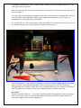
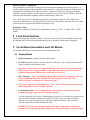
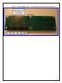
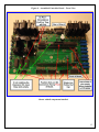
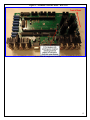
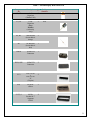
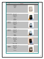
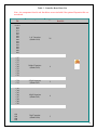
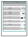
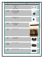
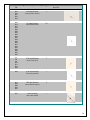
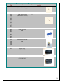
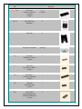
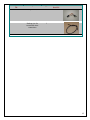
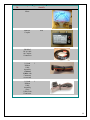
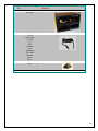
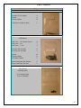
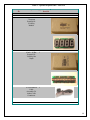
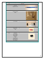
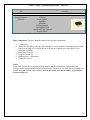
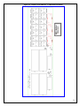
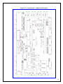
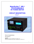
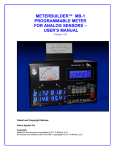
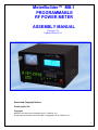
2 Introduction Thank you for purchasing the MeterBuilder MB-1 Power Meter. This manual describes the steps for assembling the kit. The operating instructions and calibration procedures are described fully in the MB1 User Manual. MB-1 consists of the following assemblies: Display/Switch Board Controller Board High Performance PIC Processor Board (already assembled) 4x20 LCD and LCD driver Daughter Board Crossneedle Analog Meter The PIC processor is a high performance Microchip PIC18F8722 processor mounted on a fully assembled and tested circuit board. This board plugs into the Controller Board in a daughter board arrangement using 40 pin headers. The PIC processor board, the LCD, and LCD driver daughter board contain surface mounted components, but these units are shipped fully assembled. There are no userinstalled surface mount components in this kit. Please check the Parts List before starting assembly. The Parts List starts in Table 2. 3 General Assembly Notes It is recommended that you use a standard 60/40 solder formula and a soldering iron of no more than 30 watts. All components should be mounted flush on the board unless otherwise noted. Because power-to-ground shorts are usually the most difficult to isolate, after installing each group of components such as the switches, the sockets, or connectors, you may want to verify that no shorts have been introduced between ground and the 5 volt bus on the Display Board, or between ground and either of the two 5 volt busses on the Controller Board. If you use this approach, if a short is detected on a power bus, you will only have to backtrack to the last installed group of components to isolate the problem. You can check for shorts by doing a simple continuity check across the 5 volt busses periodically during assembly. If you decide to follow this suggestion, locations where you can perform these checks are given below: Convenient Capacitor Locations to check for power bus shorts: The Display Board has a single 5 volt bus. The Controller Board has two 5 volt busses: +5V, and +5VAUX. Display/Switch Board - Pads of Electrolytic Capacitor C4 Controller Board o +5V – Pads of Electrolytic Capacitor C15 o +5V-AUX – Pads of Electrolytic Capacitor C14 Reducing Assembly Time The capacitors and resistors are the most numerous parts. If you put each resistor value in its own bin or tray (e.g., 33 ohms, 100 ohms, etc), you will find that it is easier to identify an empty slot for a resistor on the PCB, read its value off the silkscreen, and then select that value from the correct bin (as 5