1
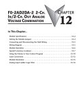
F0-04THM 4-CHANNEL
THERMOCOUPLE INPUT
CHAPTER
15
In This Chapter...
Module Specifications . . . . . . . . . . . . . . . . . . . . . . . . . . . . . . . . . . . . . . . . . . . . . . .15–2
Connecting and Disconnecting the Field Wiring . . . . . . . . . . . . . . . . . . . . . . . . . .15–4
Module Operation . . . . . . . . . . . . . . . . . . . . . . . . . . . . . . . . . . . . . . . . . . . . . . . . . .15–7
Special V-memory Locations . . . . . . . . . . . . . . . . . . . . . . . . . . . . . . . . . . . . . . . . . .15–8
Configuring the Module in Your Control Program . . . . . . . . . . . . . . . . . . . . . . .15–12
Negative Temperature Readings with Magnitude Plus Sign . . . . . . . . . . . . . . . .15–16
Module Resolution . . . . . . . . . . . . . . . . . . . . . . . . . . . . . . . . . . . . . . . . . . . . . . . .15–18
Analog Input Ladder Logic Filter . . . . . . . . . . . . . . . . . . . . . . . . . . . . . . . . . . . . .15–19
Thermocouple Burnout Detection Bits . . . . . . . . . . . . . . . . . . . . . . . . . . . . . . . . .15–21
Chapter 15: F0-04THM 4-Channel Thermocouple Input
1
2
3
4
5
6
7
8
9
10
11
12
13
14
15
B
C
D
Module Specifications
15–2
The F0-04THM 4-Channel Thermocouple Input Module
provides the following features and benefits:
• Four thermocouple input channels with 16-bit voltage
resolution or 0.1 °C/°F temperature resolution.
• Automatically converts type E, J, K, R, S, T, B, N, or C
thermocouple signals into direct temperature readings. No
extra scaling or complex conversion is required.
• Temperature data can be expressed in °F or °C.
• Module can be configured as 0–39.0625mVDC,
±39.0625mVDC,
±78.125mVDC,
0–156.25mV,
±156.25mVDC and 0–1.25VDC input and will convert
volts and millivolt signal levels into 16-bit digital (0–65535)
values.
• Signal processing features include automatic cold junction
compensation (CJC), thermocouple linearization, and digital
filtering.
• The temperature calculation and linearization are based on
data provided by the National Institute of Standards and
Technology (NIST).
• Diagnostic features include detection of thermocouple
burnout or disconnection.
R
PW
N
RU
U
CP
TX1
1
RX
TX2
2
RX
NOTE: The DL05 CPU’s analog feature for this module requires DirectSOFT32 Version 3.0c (or later) and
firmware version 4.60 (or later). The DL06 requires DirectSOFT32 version V4.0, build 16 (or later) and
firmware version 1.40 (or later). See our website for more information: www.automationdirect.com.
DL05/06 Option Modules User Manual; 7th Ed., Rev. A, 08/11
Chapter 15: F0-04THM 4-Channel Thermocouple Input
The following tables provide the specifications for the F0-04THM Analog Input Module.
Review these specifications to make sure the module meets your application requirements.
General Specifications
Number of Channels
Common Mode Range
Conversion Time
Common Mode Rejection
Input Impedance
Absolute Maximum Ratings
Accuracy vs. Temperature
Max. full scale error (including offset)
PLC Update Rate
Power Budget Requirement
Operating Temperature
Storage Temperature
Relative Humidity
Environmental Air
Vibration
Shock
Noise Immunity
Replacement Terminal Block
Wire Size Range & Connector Screw Torque
4, differential inputs, voltage or thermocouple
-1.3VDC to +3.8VDC
270ms / channel
> 100dB @ 50/60Hz.
5M⏲ min.
Fault-protected inputs to ±50 VDC
±15 ppm / ºC maximum;
0 - 1.25V ±35ppm / ºC maximum
4 channels per scan
30mA @ 5VDC (supplied by base)
0 to 60 ºC (32 to 140 ºF)
-20 to 70 ºC (-4 to 158 ºF)
5 to 95% (non-condensing)
No corrosive gases permitted
MIL STD 810C 514.2
MIL STD 810C 516.2
NEMA ICS3-304
F0-IOCON-THM (comes with CJC)
22 - 16 AWG; 0.192Nm; DN-SS1 Screwdriver Recommended
Thermocouple Specifications
Input Ranges
Display Resolution
Cold Junction Compensation
Warm-Up Time
Linearity Error (End to End)
Maximum Inaccuracy
Type J -190 to 760 ºC (-310 to 1400 ºF)
Type K -150 to 1372 ºC (-238 to 2502 ºF)
Type E -210 to 1000 ºC (-346 to 1832 ºF)
Type R 65 to 1768 ºC (149 to 3214 ºF)
Type S 65 to 1768 ºC (149 to 3214 ºF)
Type T -230 to 400 ºC (-382 to 752 ºF)
Type B 529 to 1820 ºC (984 to 3308 ºF)
Type N -70 to 1300 ºC (-94 to 2372 ºF)
Type C 65 to 2320 ºC (149 to 4208 ºF)
±0.1 ºC or ±0.1 ºF
Automatic
30 minutes typically ± 1 ºC repeatability
±1 ºC maximum, ±0.5 ºC typical
±3 ºC (excluding thermocouple error)
Voltage Input Specifications
Voltage Ranges
Resolution
Max. Offset Error (All Input Ranges)
Linearity Error (All Input Ranges)
Maximum Inaccuracy
0-39.0625mVDC, ±39.0625mVDC, ±78.125mVDC,
0-156.25mVDC, ±156.25mVDC, 0-1.25VDC
16 bit (1 in 65535)
0.05% @ 0-60 ºC; Typical: 0.04% @ 25 ºC
0.05% @ 0-60 ºC; Typical: 0.03% @ 25 ºC
0-39.0625mVDC, ±39.0625mVDC, ±78.125mVDC ranges:
0.1% @ 0-60ºC; Typical: 0.04% @ 25ºC
0-156.25mVDC, ±156.25mVDC, 0-1.25VDC ranges:
0.05% @ 0-60ºC; Typical: 0.04% @ 25ºC
1
2
3
4
5
6
7
8
9
10
11
12
13
14
15
B
C
D
All percentages are calculated as a percent of 216 (65536) counts. (0.025% max error => 0.025 * 65536/100 = 16 counts max error)
DL05/06 Option Modules User Manual; 7th Ed., Rev. A, 08/11
15–3
Chapter 15: F0-04THM 4-Channel Thermocouple Input
Wiring Guidelines
Your company may have guidelines for wiring and cable installation. If so, you should check
those before you begin the installation. Here are some general things to consider:
• Use the shortest wiring route whenever possible.
• Use shielded wiring and ground the shield at the PLC power source. Do not ground the shield at both
the transmitter and the PLC power source.
• Use thermocouple extension wire that is the same as the thermocouple type when extending the
length.
• Do not run the signal wiring next to large motors, high current switches, or transformers. This may
cause noise problems.
• Route the wiring through an approved cable housing to minimize the risk of accidental damage.
Check local and national codes to choose the correct method for your application.
To remove the terminal block, disconnect power to the PLC and the field devices. Pull the
terminal block firmly until the connector separates from the module.
You can remove the thermocouple module from the PLC by folding out the retaining tabs at the
top and bottom of the module. As the retaining tabs pivot upward and outward, the module’s
connector is lifted out of the PLC socket. Once the connector is free, you can lift the module
out of its slot.
Use the following diagram to connect the field wiring. If necessary, the F0–04THM terminal
block can be removed to make removal of the module possible without disturbing field wiring.
Thermocouple Input Wiring Diagram
All of the module’s CH– terminals must be connected together. This will help eliminate ground
potential differences between the input channels that could cause damage to the module. The
two unlabeled terminals are internally connected and may be used for convenience to connect
the CH– terminals together as shown below.
Notes:
1. Shields should be grounded at the PLC power source only.
2. All CH- terminals must be connected together.
3. Unused channels should have a shorting wire (jumper) installed
from CH+ to CH-.
See NOTE 1
CH1+
CH1–
See NOTE 2
CH2+
CJC
LM35
CJC
CJC
ADC
15–4
CH2–
MUX
The LM35
shown in the
diagram is the
CJC
internal
connection
1
2
3
4
5
6
7
8
9
10
11
12
13
14
15
B
C
D
Connecting and Disconnecting the Field Wiring
CH3+
CH3–
The CJC comes installed
on the terminal strip
CH4+
See NOTE 3
CH4–
DL05/06 Option Modules User Manual; 7th Ed. Rev. A, 08/11
Chapter 15: F0-04THM 4-Channel Thermocouple Input
Thermocouples
Use shielded thermocouples whenever possible to minimize the presence of noise on the
thermocouple wire. Ground the shield wire at one end only. For both grounded and ungrounded
thermocouples, connect the shield to the 0V (common) terminal of the PLC power supply.
Grounded Thermocouple Assembly
A grounded thermocouple provides better response time than an ungrounded thermocouple
because the tip of the thermocouple junction is in direct contact with the protective case.
Ungrounded Thermocouple Assembly
An ungrounded thermocouple is electrically isolated from the protective case. If the case is
electrically grounded it provides a low-impedance path for electrical noise to travel. The
ungrounded thermocouple provides a more stable and accurate measurement in a noisy
environment. To avoid exceeding the common mode specifications, be sure that the machine
assembly is properly bonded together.
Exposed Grounded Thermocouple
The thermocouple does not have a protective case and is directly connected to a device with a
higher potential. Grounding the thermocouple assures that the thermocouple remains within the
common mode specifications. Because a thermocouple is essentially a wire, it provides a lowimpedance path for electrical noise. The noise filter has a response of >100dB @ 50/60 Hz.
WARNING: A thermocouple can become shorted to a high voltage potential. Because common terminals
are internally connected together, whatever voltage potential exists on one thermocouple will exist on the
other channels.
Ambient Variations in Temperature
The F0-04THM module has been designed to operate within the ambient temperature range
of 0 °C to 60 °C.
The cold junction compensation is calibrated to operate in a still-air environment. If the
module is used in an application that has forced convection cooling, an error of 2–3 °C may be
introduced. To compensate for this you can use ladder logic to correct the values.
When configuring the system design it is best to locate any heat-producing devices above and
away from the PLC chassis because the heat will affect the temperature readings. For example,
heat introduced at one end of the terminal block can cause a channel-to-channel variation.
When exposing the F0-04THM module to abrupt ambient temperature changes it will take
several minutes for the cold junction compensation and terminal block to stabilize. Errors
introduced by abrupt ambient temperature changes will be less than 4 °C.
DL05/06 Option Modules User Manual; 7th Ed. Rev. A, 08/11
1
2
3
4
5
6
7
8
9
10
11
12
13
14
15
B
C
D
15–5
Chapter 15: F0-04THM 4-Channel Thermocouple Input
Voltage Input Wiring Diagram
All of the module’s CH– terminals must be connected together as shown below. This will help
eliminate ground potential differences between the input channels that could cause damage to
the module. The two unlabeled terminals are internally connected and may be used for
convenience to connect the CH– terminals together as shown below.
Notes: 1. Shields should be grounded at the PLC power source.
2. All CH– terminals must be connected together.
3. Unused channels should have a shorting wire (jumper) installed from CH+ to CH–.
4. CJC functionality is automatically disabled when a Voltage input is selected.
–
Transmitter
Supply
+
CH1+
Voltage
Transmitter
CH1–
CH2+
See NOTE 3
CH2–
CJC
LM35
CJC
Self-powered
Voltage
Transmitter
See NOTE 1
+
–
ADC
CJC
MUX
The LM35 shown
in the diagram is
the CJC
internal
connection
1
2
3
4
5
6
7
8
9
10
11
12
13
14
15
B
C
D
CH3+
CH3–
See NOTE 2
+
CH4+
Voltage
Transmitter
15–6
+
–
CH4–
DL05/06 Option Modules User Manual; 7th Ed. Rev. A, 08/11
The CJC
comes
installed on
the terminal
strip.
See NOTE 4
Chapter 15: F0-04THM 4-Channel Thermocouple Input
Module Operation
Channel Scanning Sequence
The DL05 and DL06 read the data from all four input channels during each scan. The CPUs
support special V-memory locations that are used to manage the data transfer. This is discussed
in more detail on the following page, “Special V–memory Locations”.
Scan
DL05/DL06 PLC
Read Inputs
Execute Application Program
Read the data
Store data
Scan N
Ch 1, 2, 3, 4
Scan N+1
Ch 1, 2, 3, 4
Scan N+2
Ch 1, 2, 3, 4
Scan N+3
Ch 1, 2, 3, 4
Scan N+4
Ch 1, 2, 3, 4
Write to Outputs
Analog Module Update
Even though the channel updates to the CPU are synchronous with the CPU scan, the module
asynchronously monitors the analog transmitter signal and converts the signal to a 16-bit binary
representation. This enables the module to continuously provide accurate measurements
without slowing down the discrete control logic in the RLL program.
The time required to sense the temperature and copy the value to V-memory is 270 milliseconds
minimum to 1080 milliseconds plus 1 scan time maximum (number of channels x 270
milliseconds + 1 scan time).
DL05/06 Option Modules User Manual; 7th Ed. Rev. A, 08/11
1
2
3
4
5
6
7
8
9
10
11
12
13
14
15
B
C
D
15–7
Chapter 15: F0-04THM 4-Channel Thermocouple Input
1
2
3
4
5
6
7
8
9
10
11
12
13
14
15
B
C
D
Special V-memory Locations
The DL05 and DL06 PLCs have special V-memory locations assigned to their respective option
slots. These V-memory locations allow you to:
• specify the number of input channels enabled and BCD/Binary data format
• specify the input pointer address
• specify the thermocouple or voltage input type
• specify the units code – temperature scale and data format
• enable/disable thermocouple burnout detection
• specify burnout data value at burnout
• read module setup diagnostics
Module Configuration Registers
The table below shows the special V-memory locations used by the DL05 and DL06 PLCs for
the F0–04THM module.
Module Configuration
Parameters
DL05 and DL06 Option Slot
DL05
Slot
DL06
Slot 1
DL06
Slot 2
DL06
Slot 3
DL06
Slot 4
V7700
V700
V710
V720
V730
V7701
V7703
V7704
V701
V703
V704
V711
V713
V714
V721
V723
V724
V731
V733
V734
V7705
V705
V715
V725
V735
F: Thermocouple Burnout
Data Value
V7706
V706
V716
V726
V736
G: Diagnostic Error
V7707
V707
V717
V727
V737
A: Number of Channels
Enabled / Data Format
B: Input Pointer
C: Input Type
D: Units Code
E: Thermocouple Burnout
Detection Enable
A: Number of Channels Enabled/Data Format Register
This V–memory location is used to define the number of input channels to be enabled and to
set the channel data to BCD or binary format.
Number of
Channel Data in Channel Data in
Channels Enabled BCD Format
Binary Format
1 Channel
2 Channels
3 Channels
4 Channels
K100
K200
K300
K400
K8100
K8200
K8300
K8400
MSB
LSB
Data Format
Number of channels
15–8
DL05/06 Option Modules User Manual; 7th Ed. Rev. A, 08/11
Chapter 15: F0-04THM 4-Channel Thermocouple Input
B: Input Pointer Register
This is a system parameter that points to a V-memory location used for storing module channel
input data. The V–memory location loaded in the input pointer V–memory location is an octal
number identifying the first V-memory location for the input data. This V–memory location is
user defined, but must use available consecutive V-memory locations. For example, loading
O2000 causes the pointer to write Ch 1’s data value to V2000/2001, Ch 2’s data value to
V2002/2003, CH 3’s data value to V2004/2005 and Ch 4’s data value to V2006/2007.
NOTE: Each channel’s data value occupies two (2) consecutive V-memory locations. This allows for more
than four (4) digits to be displayed if a BCD format for channel data is selected. For example: 1234.5 °F.
A binary format for either a 15-bit magnitude plus sign or 16-bit 2’s complement value will occupy the first
V-memory location of the two V-memory locations assigned for the slected channel.
Refer to the specific PLC’s user manual being used for available user V-memory locations.
C: Input Type Selection Register
This V–memory register must be set to match the type of thermocouple being used or the input
voltage level. Use the table to determine your settings.
Thermocouple/
Voltage Input Type
Input
Selection
Temperature
Range °C
Temperature
Range °F
J
K
E
R
S
T
B
N
C
0-39.0625mVDC
±39.0625mVDC
±78.125mVDC
0-156.25mVDC
±156.25mVDC
0-1.25VDC
K0
K1
K2
K3
K4
K5
K6
K7
K8
K9
KA
KB
KC
KD
KE
-190 to 760
-150 to 1372
-210 to 1000
65 to 1768
65 to 1768
-230 to 400
529 to 1820
-70 to 1300
65 to 2320
N/A
N/A
N/A
N/A
N/A
N/A
-310 to 1400
-238 to 2502
-346 to 1832
149 to 3214
149 to 3214
-382 to 752
984 to 3308
-94 to 2372
149 to 4208
N/A
N/A
N/A
N/A
N/A
N/A
MSB
LSB
Input Type
Selection
NOTE: The CJC functionality is automatically disabled when a Voltage input is selected.
DL05/06 Option Modules User Manual; 7th Ed. Rev. A, 08/11
1
2
3
4
5
6
7
8
9
10
11
12
13
14
15
B
C
D
15–9
Chapter 15: F0-04THM 4-Channel Thermocouple Input
D: Units Code Register
1
2
3
4
5
6
7
8
9
10
11
12
13
14
15
B
C
D
15–10
All thermocouple types are converted into a direct temperature reading in either Fahrenheit or
Celsius. The data contains one implied decimal place. For example, a value in V-memory of
1002 would be 100.2 °C or °F.
For thermocouple ranges which include negative temperatures (J,E,K,T,N), the display
resolution is from –3276.7 to +3276.7. For positive-only thermocouple ranges (R,S,B,C), the
display resolution is 0 to 6553.5.
Negative temperatures can be represented in either 2’s complement or magnitude plus sign
form. If the temperature is negative, the most significant bit in the V-memory location is set.
The 2’s complement data format may be required to correctly display bipolar data on some
operator interfaces. This data format could also be used to simplify averaging a bipolar signal.
To view this data format in DirectSoft32, select Signed Decimal.
For unipolar thermocouple ranges (R,S,B,C), it does not matter if magnitude plus sign or 2’s
complement is selected.
The bipolar voltage input ranges may be converted to a 15-bit magnitude plus sign or a 16-bit
2’s complement value.
Bit 0 = Temperature Scale
(ignored if Voltage input is selected)
0 = Temp in degrees F
1 = Temp in degrees C
Bit 1 = Data Format
0 = Magnitude plus sign bit format
1 = 2’s Complement format
Unit Code Register - Truth Table
Temperature Scale
Data Format
Bit 1
Bit 0
Value
°F
Magnitude + sign bit
0
0
K0
°C
Magnitude + sign bit
0
1
K1
°F
2’s Complement
1
0
K2
°C
2’s Complement
1
1
K3
Temp scale
MSB
LSB
Data Format
DL05/06 Option Modules User Manual; 7th Ed. Rev. A, 08/11
Chapter 15: F0-04THM 4-Channel Thermocouple Input
E: Thermocouple Burnout Detection Enable Register
This register is used to enable/disable the thermocouple burnout function. Be sure to disable the
burnout detection function when checking the module calibration.
Bit 0 = Thermocouple Burnout Detection Enable/Disable
0 = Burnout detection is enabled
1 = Burnout detection is disabled
MSB
LSB
Burnout
Function
F: Thermocouple Burnout Data Value Register
This register is used to define either up scale or down scale channel values when a channel
thermocouple burnout occurs.
Bit 0 = Up scale/down scale value at Burnout
0 = Up scale value at Burnout:
Unipolar input type: FFFFh (BCD/HEX) or 65535 (Binary)
written to CH register
Bipolar input type: 7FFFh (BCD/HEX) or 32767 (Binary)
written to CH register
1 = Down scale value at Burnout:
0000h (BCD/HEX) or 0 (Binary) written to CH register
MSB
LSB
Up scale/down scale Burnout value
G: Diagnostics Error Register
This register is used to determine whether the configuration of the module is valid or not. It is
controlled by the PLC and is read only.
Bit 0 = Diagnostic bit:
0 = Module setup is valid
1 = Module setup is not valid
MSB
LSB
Diagnostics bit
DL05/06 Option Modules User Manual; 7th Ed. Rev. A, 08/11
1
2
3
4
5
6
7
8
9
10
11
12
13
14
15
B
C
D
15–11
Chapter 15: F0-04THM 4-Channel Thermocouple Input
1
2
3
4
5
6
7
8
9
10
11
12
13
14
15
B
C
D
Configuring the Module in Your Control Program
DL05 Example 1
15–12
The example program below shows how to setup the F0–04THM for 4 input channels enabled,
J type thermocouple on all 4 input channels, BCD channel data format, ºF temperature scale,
magnitude plus sign bit format, and burnout detection enabled with an up scale burnout
specified. Place this rung anywhere in the ladder program or in the initial stage if you are using
stage programming instructions.
This is all that is required to read the temperature or voltage input data into V-memory
locations. Once the data is in V-memory you can perform mathematical calculations with the
data, compare the data against preset values, etc. V2000 is used in the example but you can use
any user V-memory location.
SP0
LD
K0400
-or -
LD
K8400
Loads a constant that specifies the number of input channels to scan
and the data format. The upper byte, most significant nibble (MSN)
selects the data format (0 = BCD, 8 = binary). The LSN selects the
number of channels (1, 2, 3 or 4).
The binary format is used for displaying data on some operator
interface units. K8400 enables 4 channels in binary format.
OUT
V7700
Special V-memory location assigned to the option slot that specifies
the data format and the number of channels to scan.
LDA
O2000
This loads an octal value for the first V-memory location that will be used
to store the incoming data. For example, the O2000 entered here using
the LDA instruction would designate the following addresses:
Ch1 – V2000/2001, Ch2 – V2002/2003, Ch3 – V2004/2005,
Ch4 – V2006/2007. See note on page 15-9.
OUT
V7701
The octal address (O2000) is stored here. Special V–memory location
V7701 is assigned to the option slot and acts as a pointer, which
means the CPU will use the octal value in this location to determine
exactly where to store the incoming data.
LD
K0
Loads a 0 into the accumulator to set the following parameters in
(V7703 – V7706).
OUT
V7703
Special V–memory location assigned to the option slot that specifies the
thermocouple input type or voltage range selection. CJC is disabled with
voltage selected. K0 selects J type thermocouple with CJC enabled.
See table on page 15-9 for selections.
OUT
V7704
Special V–memory location assigned to the option slot that specifies
the Units Code (temperature scale and data format) selections.
K0 selects º F temperature scale and magnitude plus sign bit format.
See truth table on page 15-10 for selections.
OUT
V7705
Special V–memory location assigned to the option slot that specifies
the thermocouple burnout detection enable/disable.
K0 selects burnout detection enabled.
OUT
V7706
Special V–memory location assigned to the option slot that specifies
the thermocouple up scale/down scale burnout value. K0 selects an
up scale value at burnout. FFFFh for unipolar inputs and 7FFFh for
bipolar inputs at burnout. The value is written to the channel input
register when a thermocouple burnout occurs.
DL05/06 Option Modules User Manual; 7th Ed. Rev. A, 08/11
Chapter 15: F0-04THM 4-Channel Thermocouple Input
DL05 Example 2
The example program below shows how to setup the F0–04THM for 2 input channels enabled,
use of a K type thermocouple on the first 2 input channels, BCD channel data format, ºC
temperature scale, 2’s complement format, and burnout detection enabled with a down scale
burnout specified. Again, place this rung in the ladder program or in the intial stage if you are
using stage programming instructions.
SP0
LD
K0200
-or -
LD
K8200
Loads a constant that specifies the number of input channels to scan
and the data format. The upper byte, most significant nibble (MSN)
selects the data format (0 = BCD, 8 = binary). The LSN selects the
number of channels (1, 2, 3 or 4).
The binary format is used for displaying data on some operator
interface units. K8200 enables 2 channels in binary format.
OUT
V7700
Special V-memory location assigned to the option slot that specifies
the data format and the number of channels to scan.
LDA
O2000
This loads an octal value for the first V-memory location that will be used
to store the incoming data. For example, the O2000 entered here using
the LDA instruction would designate the following addresses:
Ch1 – V2000/2001, Ch2 – V2002/2003
See note on page 15-9.
OUT
V7701
The octal address (O2000) is stored here. Special V–memory location
V7701 is assigned to the option slot and acts as a pointer, which
means the CPU will use the octal value in this location to determine
exactly where to store the incoming data.
LD
K1
Loads a constant that specifies the input type. K1 selects K type
thermocouple with CJC enabled. Enter a K0–K14 to specify the input
type. See table on page 15-9 for selections.
OUT
V7703
Special V–memory location assigned to the option slot that specifies
the thermocouple input type or voltage range selection. CJC is
disabled when voltage is selected.
LD
K3
Loads a constant that specifies the Units Code (temperature scale and
data format). K3 selects º C and 2’s complement data format.
See truth table on page 15-10 for selections.
OUT
V7704
Special V–memory location assigned to the option slot that specifies
the temperature scale and data format selections.
LD
K0
Loads a constant that enables/disables the thermocouple burnout
detection function. K0 selects burnout function enabled.
OUT
V7705
Special V–memory location assigned to the option slot that specifies
the thermocouple burnout detection enable/disable.
LD
K1
Loads a constant that specifies the thermocouple burnout data value at
burnout. K1 specifies a down scale value of 0000h to be written to the
channel input register when a thermocouple burnout occurs.
OUT
V7706
Special V–memory location assigned to the option slot that specifies the
thermocouple up scale/down scale burnout value. The value is written
to the channel input register when a thermocouple burnout occurs.
DL05/06 Option Modules User Manual; 7th Ed. Rev. A, 08/11
1
2
3
4
5
6
7
8
9
10
11
12
13
14
15
B
C
D
15–13
Chapter 15: F0-04THM 4-Channel Thermocouple Input
DL06 Example 1
1
2
3
4
5
6
7
8
9
10
11
12
13
14
15
B
C
D
15–14
The example program below shows how to setup the F0–04THM in option slot 1 for 4 input
channels enabled, use of a J type thermocouple on all 4 input channels, BCD channel data
format, ºF temperature scale and magnitude plus sign bit format, and burnout detection
enabled with an up scale burnout specified. Use the table shown on page 15–8 to determine the
pointer values if locating the module in any of the other slots. Place this rung anywhere in the
ladder program or in the initial stage if you are using stage programming instructions.
This is all that is required to read the temperature or voltage input data into V-memory
locations. Once the data is in V-memory you can perform mathematical calculations with the
data, compare the data against preset values, etc. V2000 is used in the example but you can use
any user V-memory location.
SP0
LD
K0400
-or -
LD
K8400
Loads a constant that specifies the number of input channels to scan
and the data format. The upper byte, most significant nibble (MSN)
selects the data format (0 = BCD, 8 = binary). The LSN selects the
number of channels (1, 2, 3 or 4).
The binary format is used for displaying data on some operator
interface units. K8400 enables 4 channels in binary format.
OUT
V700
Special V-memory location assigned to option slot 1 that specifies
the data format and the number of channels to scan.
LDA
O2000
This loads an octal value for the first V-memory location that will be used
to store the incoming data. For example, the O2000 entered here using
the LDA instruction would designate the following addresses:
Ch1 – V2000/2001, Ch2 – V2002/2003, Ch3 – V2004/2005,
Ch4 – V2006/2007. See note on page 15-9.
OUT
V701
The octal address (O2000) is stored here. Special V–memory location
V701 is assigned to option slot 1 and acts as a pointer, which means
the CPU will use the octal value in this location to determine exactly
where to store the incoming data.
LD
K0
Loads a 0 into the accumulator to set the following parameters in
(V703 – V706).
OUT
V703
Special V–memory location assigned to option slot 1 that specifies the
thermocouple input type or voltage range selection. CJC is disabled with
voltage selected. K0 selects J type thermocouple and CJC enabled.
See table on page 15-9 for selections.
OUT
V704
Special V–memory location assigned to option slot 1 that specifies
the Units Code (temperature scale and data format) selections.
K0 selects º F temperature scale and magnitude plus sign bit format.
See truth table on page 15-10 for selections.
OUT
V705
Special V–memory location assigned to option slot 1 that specifies
the thermocouple burnout detection enable/disable.
K0 selects burnout detection enabled.
OUT
V706
Special V–memory location assigned to option slot 1 that specifies the
thermocouple up scale/down scale burnout value at burnout. K0
selects an up scale value at burnout. FFFFh for unipolar inputs and
7FFFh for bipolar inputs. The value is written to the channel input
register when a thermocouple burnout occurs.
DL05/06 Option Modules User Manual; 7th Ed. Rev. A, 08/11
Chapter 15: F0-04THM 4-Channel Thermocouple Input
DL06 Example 2
The example program below shows how to setup the F0–04THM in option slot 2 for 2 input
channels enabled, use of a K type thermocouple on the first 2 input channels, BCD channel
data format, ºC temperature scale, 2’s complement format, and burnout detection enabled
with a down scale burnout specified. Use the table shown on page 15–8 to determine the
pointer values if locating the module in any of the other slots. V-memory location V3000 is
shown in the example, but you can use any available user V-memory location. Again, place this
rung anywhere in the ladder program or in the initial stage if you are using stage programming
instructions.
SP0
LD
K0200
- or -
LD
K8200
Loads a constant that specifies the number of input channels to scan
and the data format. The upper byte, most significant nibble (MSN)
selects the data format (0 = BCD, 8 = binary). The LSN selects the
number of channels (1, 2, 3 or 4).
The binary format is used for displaying data on some operator
interface units. K8200 enables 2 channels in binary format.
OUT
V710
Special V-memory location assigned to option slot 2 that specifies
the data format and the number of channels to scan.
LDA
O3000
This loads an octal value for the first V-memory location that will be used
to store the incoming data. For example, the O3000 entered here using
the LDA instruction would designate the following addresses:
Ch1 – V3000/3001, Ch2 – V3002/3003
See note on page 15-9.
OUT
V711
The octal address (O3000) is stored here. Special V–memory location
V711 is assigned to option slot 2 and acts as a pointer, which
means the CPU will use the octal value in this location to determine
exactly where to store the incoming data.
LD
K1
Loads a constant that specifies the input type. K1 selects K type
thermocouple with CJC enabled. Enter a K0–K14 to specify the input
type. See table on page 15-9 for selections.
OUT
V713
Special V–memory location assigned to option slot 2 that specifies
the thermocouple input type or voltage range selection. CJC is
disabled when voltage is selected.
LD
K3
Loads a constant that specifies the Units Code (temperature scale and
data format). K3 selects º C and 2’s complement data format.
See truth table on page 15-10 for selections.
OUT
V714
Special V–memory location assigned to option slot 2 that specifies
the temperature scale and data format selections.
LD
K0
Loads a constant that enables/disables the thermocouple burnout
detection function. K0 selects burnout function enabled.
OUT
V715
Special V–memory location assigned to option slot 2 that specifies
the thermocouple burnout detection enable/disable.
LD
K1
Loads a constant that specifies the thermocouple burnout data value.
K1 specifies a down scale value of 0000h to be written to the channel
input register when a thermocouple burnout occurs.
OUT
V716
Special V–memory location assigned to option slot 2 that specifies the
thermocouple up scale/down scale burnout value. The value is written
to the channel input register when a thermocouple burnout occurs.
DL05/06 Option Modules User Manual; 7th Ed. Rev. A, 08/11
1
2
3
4
5
6
7
8
9
10
11
12
13
14
15
B
C
D
15–15
Chapter 15: F0-04THM 4-Channel Thermocouple Input
1
2
3
4
5
6
7
8
9
10
11
12
13
14
15
B
C
D
Negative Temperature Readings with Magnitude Plus Sign
With bipolar ranges, you need some additional logic to determine whether the value being
returned represents a positive temperature/voltage or a negative temperature/voltage. There is a
simple solution:
• If you are using bipolar ranges and you get a value greater than or equal to 8000h, the value is
negative.
• If you get a value less than or equal to 7FFFh, the value is positive.
The sign bit is the most significant bit, which combines 8000h to the data value. If the value is
greater than or equal to 8000h, you only have to mask the most significant bit and the active
channel bits to determine the actual data value.
The following two programs show how you can accomplish this. The first example uses
magnitude plus sign (binary) and the second example uses magnitude plus sign (BCD).
Since you always want to know when a value is negative, these rungs should be placed before
any other operations that use the data, such as math instructions, scaling operations, and so
forth. Also, if you are using stage programming instructions, these rungs should be in a stage
that is always active. Note: you only need this logic for each channel that is using bipolar input
signals. The examples only show two channels.
Magnitude Plus Sign (Binary)
15–16
Check Channel 1
SP1
V2000
LD
V2000
Load channel 1 data from V-memory into the
accumulator. Contact SP1 is always on.
AND
K7FFF
This instruction masks the sign bit of the binary data, if
it is set. Without this step, negative values will not be
correct so do not forget to include it.
OUT
V2010
Put the actual signal value in V2010. Now you can use
the data normally.
K8000
욷
Check Channel 2
SP1
V2002
K8000
욷
C1
OUT
Channel 1 data is negative when C1 is on (a value of
–1.0 reads as 8010, –2.0 is 8020, etc.).
LD
V2002
Load channel 2 from V-memory into the accumulator.
Contact SP1 is always on.
AND
K7FFF
This instruction masks the sign bit of the binary data, if
it is set. Without this step, negative values will not be
correct so do not forget to include it.
OUT
V2012
Put the actual signal value in V2012. Now you can use
the data normally.
C2
OUT
Channel 2 data is negative when C2 is on (a value of
–1.0 reads as 8010, –2.0 is 8020, etc.).
DL05/06 Option Modules User Manual; 7th Ed. Rev. A, 08/11
Chapter 15: F0-04THM 4-Channel Thermocouple Input
Magnitude Plus Sign (BCD)
Check Channel 1
SP1
V2001
LDD
V2000
Load channel 1 data from V-memory into the
accumulator. Remember, the data can be negative.
Contact SP1 is always on.
ANDD
K7FFFFFFF
This instruction masks the sign bit of the BCD data, if it
is set. Without this step, negative values will not be
correct so do not forget to include it.
OUTD
V2010
Put the actual signal value in V2010. Now you can use
the data normally.
K8000
C1
욷
OUT
Check Channel 2
SP1
V2003
K8000
욷
Channel 1 data is negative when C1 is on (a value of
–1.0 reads as 8000 0010, –2.0 is 8000 0020, etc.).
LDD
V2002
Load channel 2 from V-memory into the accumulator.
Remember, the data can be negative. Contact SP1 is
always on.
ANDD
K7FFFFFFF
This instruction masks the sign bit of the BCD data, if it
is set. Without this step, negative values will not be
correct so do not forget to include it.
OUTD
V2012
Put the actual signal value in V2012. Now you can use
the data normally.
C2
OUT
Channel 2 data is negative when C2 is on (a value of
–1.0 reads as 8000 0010, –2.0 is 8000 0020, etc.).
DL05/06 Option Modules User Manual; 7th Ed. Rev. A, 08/11
1
2
3
4
5
6
7
8
9
10
11
12
13
14
15
B
C
D
15–17
Chapter 15: F0-04THM 4-Channel Thermocouple Input
1
2
3
4
5
6
7
8
9
10
11
12
13
14
15
B
C
D
Module Resolution
Module Resolution 16-Bit (Unipolar Voltage Input)
Unipolar analog signals are converted
into 65536 (216) counts ranging from 0
to 65535. For example, with a 0 to
156.25mVDC signal range, 78mVDC
would be 32767. A value of 65535
represents the upper limit of the range.
Unipolar Resolution =
5VDC
156.25
mVDC
2.5VDC
78
mVDC
0VDC
0 VDC
H–L
65535
H or L = high or low limit of the range
0
32767
65535
Counts
Module Resolution 15-Bit Plus Sign (Bipolar Voltage Input)
15–18
The module has 16-bit unipolar or 15bit + sign bipolar resolution. Bipolar
analog signals are converted into 32768
(215) counts ranging from 0 to 32767.
For example, with a –156.25mVDC to
156.25mVDC input signal range,
156.25mVDC would be 32767. The
bipolar ranges utilize a sign bit to
provide 16-bit resolution. A value of
32767 can represent the upper limit of
either side of the range. Use the sign bit
to determine negative values.
156.25
mVDC
5 VDC
0 VDC
0 VDC
–156.25 –5 VDC
mVDC
32767
(sign bit = 1)
0
Counts
Bipolar Resolution =
H–L
32767
H or L = high or low limit of the range
DL05/06 Option Modules User Manual; 7th Ed. Rev. A, 08/11
32767
(sign bit = 0)
Chapter 15: F0-04THM 4-Channel Thermocouple Input
Analog Input Ladder Logic Filter
PID Loops / Filtering:
Please refer to the “PID Loop Operation” chapter in the DL06 or DL05 User Manual for
information on the built-in PV filter (DL05/06) and the ladder logic filter (DL06 only) shown
below. A filter must be used to smooth the analog input value when auto tuning PID loops to
prevent giving a false indication of loop characteristics.
Smoothing the Input Signal (DL06 only):
The filter logic can also be used in the same way to smooth the analog input signal to help
stabilize PID loop operation or to stabilize the analog input signal value for use with an operator
interface display, etc.
WARNING: The built-in and logic filters are not intended to smooth or filter noise generated by improper
field device wiring or grounding. Small amounts of electrical noise can cause the input signal to bounce
considerably. Proper field device wiring and grounding must be done before attempting to use the filters
to smooth the analog input signal.
Using Binary Data Format
SP1
LD
V2000
Loads the analog signal, which is in binary format
and has been loaded from V-memory location
V2000, into the accumulator. Contact SP1 is
always on.
BTOR
Converts the binary value in the accumulator
to a real number.
SUBR
V1400
Subtracts the real number stored in location
V1400 from the real number in the accumulator,
and stores the result in the accumulator. V1400
is the designated workspace in this example.
MULR
R0.2
Multiplies the real number in the accumulator by
0.2 (the filter factor), and stores the result in the
accumulator. This is the filtered value. The filter
range is 0.1 to 0.9. Smaller filter factors
increases filtering. (1.0 eliminates filtering).
ADDR
V1400
Adds the real number stored in
location V1400 to the real number
filtered value in the accumulator, and
stores the result in the accumulator.
OUTD
V1400
Copies the value in the accumulator to
location V1400.
RTOB
Converts the real number in the
accumulator to a binary value, and
stores the result in the accumulator.
OUT
V1402
Loads the binary number filtered value from
the accumulator into location V1402 to use in
your application or PID loop.
DL05/06 Option Modules User Manual; 7th Ed. Rev. A, 08/11
1
2
3
4
5
6
7
8
9
10
11
12
13
14
15
B
C
D
15–19
Chapter 15: F0-04THM 4-Channel Thermocouple Input
1
2
3
4
5
6
7
8
9
10
11
12
13
14
15
B
C
D
NOTE: Be careful not to do a multiple number conversion on a value. For example, if you are using the pointer
method in BCD format to get the analog value, it must be converted to binary (BIN) as shown below. If you
are using the pointer method in Binary format, the conversion to binary (BIN) instruction is not needed.
Using BCD Data Format
15–20
SP1
LDD
V2000
Loads the analog signal, which is in BCD format
and has been loaded from V-memory location
V2000, into the accumulator. Contact SP1 is
always on.
BIN
Converts a BCD value in the accumulator to
binary.
BTOR
Converts the binary value in the accumulator
to a real number.
SUBR
V1400
Subtracts the real number stored in location
V1400 from the real number in the accumulator,
and stores the result in the accumulator. V1400
is the designated workspace in this example.
MULR
R0.2
Multiplies the real number in the accumulator by
0.2 (the filter factor), and stores the result in the
accumulator. This is the filtered value. The filter
range is 0.1 to 0.9. Smaller filter factors
increases filtering. (1.0 eliminates filtering).
ADDR
V1400
Adds the real number stored in
location V1400 to the real number
filtered value in the accumulator, and
stores the result in the accumulator.
OUTD
V1400
Copies the value in the accumulator to
location V1400.
RTOB
Converts the real number in the
accumulator to a binary value, and
stores the result in the accumulator.
BCD
OUTD
V1402
Converts the binary value in the accumulator
to a BCD number. Note: The BCD instruction
is not needed for PID loop PV (loop PV is a
binary number).
Loads the BCD number filtered value from
the accumulator into location V1402 to use in
your application or PID loop.
DL05/06 Option Modules User Manual; 7th Ed. Rev. A, 08/11
Chapter 15: F0-04THM 4-Channel Thermocouple Input
Thermocouple Burnout Detection Bits
Special Relays Corresponding to Thermocouple Burnouts
The following Special Relay (SP) bits can be used in your program to monitor for thermocouple
burnout.
SP bit :
0 = Thermocouple OK
1 = Thermocouple burnout
DL05 and DL06 Option Slot
Module Channel
DL05
Slot
DL06
Slot 1
DL06
Slot 2
DL06
Slot 3
DL06
Slot 4
Channel 1
SP600
SP140
SP240
SP340
SP440
Channel 2
SP601
SP141
SP241
SP341
SP441
Channel 3
SP602
SP142
SP242
SP342
SP442
Channel 4
SP603
SP143
SP243
SP343
SP443
DL05/06 Option Modules User Manual; 7th Ed. Rev. A, 08/11
1
2
3
4
5
6
7
8
9
10
11
12
13
14
15
B
C
D
15–21
DL05/06 Option Modules User Manual; 7th Ed. Rev. A, 08/11