1
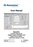
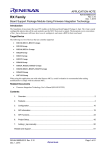
User Manual
NanoCAN
Application for stepper motor controls and Plug & Drive motors
(version V2.0.0.1)
NANOTEC ELECTRONIC GmbH & Co. KG
Kapellenstraße 6
D-85622 Feldkirchen b. Munich, Germany
Tel.
+49 (0)89-900 686-0
Fax
+49 (0)89-900 686-50
[email protected]
Benutzerhandbuch
NanoCAN
Editorial
Editorial
© 2012
Nanotec® Electronic GmbH & Co. KG
Kapellenstraße 6
D-85622 Feldkirchen b. Munich, Germany
Tel.:
Fax:
+49 (0)89-900 686-0
+49 (0)89-900 686-50
Internet: www.nanotec.com
All rights reserved!
MS-Windows 2000/XP/Vista are registered trademarks of Microsoft Corporation.
Translation of the original operation manual
Version/Change overview
2 / 56
Version
Date
Changes
1.0
06/20/2009
New issue enders
1.1
12/14/2009
Revision C+P
1.2
12/13/2010
Revision C+P, program version 1.35
2.0
11/03/2011
Revision enders/C+P, program version 2.00
2.0.0.1
04/23/2012
Revision enders/C+P, program version V2.0.0.1
Issue: V2.0.0.1
Benutzerhandbuch
NanoCAN
About this manual
About this manual
Target group
This user manual is aimed at designers and developers who need to configure a
CANopen-capable motor control from Nanotec® with the aid of the NanoCAN
software without much experience in stepper motor technology.
Important information
This user manual must be carefully read before installation of the software.
Nanotec® reserves the right to make technical alterations and further develop
hardware and software in the interests of its customers to improve the function of
this product without prior notice.
For criticisms, proposals and suggestions for improvement, please contact the
above address or send an email to: [email protected]
Additional manuals
Please also note the following manuals from Nanotec:
Nanotec CANopen
reference
Comprehensive documentation
of the CANopen functions
Technical manuals
Connection and commissioning
of stepper motor controls or
Plug & Drive motors
The manuals are available for download at www.nanotec.com.
Issue: V2.0.0.1
3 / 56
Benutzerhandbuch
NanoCAN
4 / 56
Issue: V2.0.0.1
Benutzerhandbuch
NanoCAN
Contents
Contents
1
Installation ............................................................................................................................ 7
System requirements ............................................................................................................. 7
Procedure............................................................................................................................... 7
2
Overview of the user interface............................................................................................ 8
Tabs (1).................................................................................................................................. 9
PDO Quickview (2)................................................................................................................. 9
Message output (3) ................................................................................................................ 9
Clear Error Log (4) ................................................................................................................. 9
Show CAN BUS Log (5)......................................................................................................... 9
Statusword display (6)............................................................................................................ 9
Status bar (7) ....................................................................................................................... 10
3
<Configuration & NMT> tab .............................................................................................. 11
3.1
User interface....................................................................................................................... 11
3.2
Selecting the control............................................................................................................. 11
Direct connection with a control ........................................................................................... 13
Searching for a control ......................................................................................................... 14
3.3
Network Management .......................................................................................................... 16
3.4
Reading out the hardware and software version ................................................................. 16
4
<Node Configuration> tab ................................................................................................. 17
4.1
User interface....................................................................................................................... 17
4.2
<Node Settings & Error> area.............................................................................................. 18
4.3
<Motor & Drive Settings> area............................................................................................. 20
4.4
<Closed Loop> area............................................................................................................. 24
5
<Object Management> tab ................................................................................................ 27
5.1
User interface....................................................................................................................... 27
5.2
<SDO List> area .................................................................................................................. 28
Changing values of an SDO ................................................................................................ 29
5.3
<PDO Mapping> area .......................................................................................................... 30
5.3.1
General information.............................................................................................................. 30
5.3.2
PDO mapping....................................................................................................................... 31
Mapping of PDOs................................................................................................................. 32
5.4
<PDO Received> area ......................................................................................................... 33
PDO Quickview .................................................................................................................... 34
6
<Drive Modes> tab ............................................................................................................. 36
6.1
General functions ................................................................................................................. 36
Activating the operation mode ............................................................................................. 36
6.2
<Homing Mode> area .......................................................................................................... 38
Selecting and starting a reference run ................................................................................. 39
6.3
<Profile Position Mode> area............................................................................................... 42
Issue: V2.0.0.1
5 / 56
Benutzerhandbuch
NanoCAN
Contents
6.4
<Velocity Mode> area .......................................................................................................... 43
6.5
<Interpolated Position Mode> area...................................................................................... 44
Starting the Interpolated Position Mode............................................................................... 45
Stopping the Interpolated Position Mode ............................................................................. 45
6.6
<Torque Mode> area ........................................................................................................... 46
7
<I/O> tab.............................................................................................................................. 47
7.1
General information.............................................................................................................. 47
7.2
[Digital Input] area ................................................................................................................ 48
7.3
[Digital Output] area ............................................................................................................. 48
7.4
[Analog Input] area............................................................................................................... 49
8
<Firmware Update> tab ..................................................................................................... 51
8.1
Firmware update: RS485 to CAN ........................................................................................ 52
8.2
Firmware update: CAN to CAN............................................................................................ 53
9
<Info> tab ............................................................................................................................ 54
10
Statusword display ............................................................................................................ 55
11
CAN Bus log window ......................................................................................................... 56
6 / 56
Issue: V2.0.0.1
Benutzerhandbuch
NanoCAN
Installation
1
Installation
System requirements
The NanoCAN software only operates with adapters from IXXAT and PEAK. The
appropriate drivers must be installed.
• IXXAT: The VCI driver (version 3) is available for download under the "Support"
section at www.ixxat.com.
• PEAK: The driver is available for download under the "Support" section (download
packages) at www.peak-system.com.
Procedure
To install NanoCAN on your PC, you must download the software from the Nanotec
website.
To do this, proceed as follows:
Step
Issue: V2.0.0.1
Action
1
Open the Nanotec website in your browser: http://www.nanotec.com
2
Go to the "Support –> Software –> NanoCAN” area.
3
Download NanoCAN.
4
Unpack the zip file on your PC in the required directory.
5
Start the program by double-clicking on the "NanoCAN.exe” file.
7 / 56
Benutzerhandbuch
NanoCAN
Overview of the user interface
2
Overview of the user interface
Function and design
The NanoCAN software can be used to easily configure the CAN communication of
the stepper motor controls and the Plug & Drive motors on a PC with a CAN interface.
Transparent interfaces and simple test functions enable rapid entry into operation and
facilitate commissioning.
Familiarize yourself with the user interface of the NanoCAN software before starting to
configure the stepper motor controls or Plug & Drive motors.
Scopes
The user interface consists of the following areas:
• Tabs (1)
• PDO Quickview (2)
• Message output (3)
• Button for resetting the message output (4)
• Button for calling up the CAN BUS log (5)
• Statusword display (6)
• Status bar (7)
View
8 / 56
Issue: V2.0.0.1
Benutzerhandbuch
NanoCAN
Overview of the user interface
Tabs (1)
The user interface consists of the following tabs:
Tab
Function
See section
<Configuration & NMT>
CANopen settings and
commands
<Configuration & NMT> tab
<Node Configuration>
Error log, motor and closed
loop settings
<Node Configuration> tab
<Object Management>
SDO list, PDO (process
data objects) configuration,
PDO Quickview settings
<Object Management> tab
<Drive Modes>
Settings for the various
drive modes
<Drive Modes> tab
<I/O>
Settings and status query of <I/O> tab
the inputs and outputs of the
control
<Firmware Update>
Update of the motor control
firmware
<Firmware Update> tab
<Info>
Information on NanoCAN
and the DLL versions used
<Info> tab
Note:
When switching to the <Drive Modes> tab, the corresponding SDO (Service Data
Object) is sent in order to switch to the selected drive mode (default: Homing Mode).
When offline mode is selected, the <Drive Modes>, <I/O> and <Firmware Update>
tabs are hidden.
PDO Quickview (2)
Here, TxPDOs which the control sends can be displayed in order to always keep their
values in view. The values are automatically updated at the same time.
Message output (3)
In the message output, various messages (including error messages) are displayed
that occur during the writing of the SDOs to the control or reading of the SDOs from
the control.
Clear Error Log (4)
This button resets the content of the message window.
Show CAN BUS Log (5)
This button can be used to open the Bus Log window. The messages sent over the
CAN bus are displayed in this window.
Further information in Section 11 "CAN Bus log window”.
Statusword display (6)
The current state of the statusword is read and the statusword is updated here.
Further information in Section 10 "Statusword display”.
Issue: V2.0.0.1
9 / 56
Benutzerhandbuch
NanoCAN
Overview of the user interface
Status bar (7)
The status bar displays the found CAN adapters, the connected CAN devices and the
current operating status of the control.
CAN adapter describes an expansion card integrated in the computer or a device
connected by USB over which the computer can understand the CAN protocol.
A CAN device, on the other hand, is a CAN-compliant end device such as a CAN
control.
Possible CAN adapter/device operating states:
State
Description
connected
A CAN adapter or control is connected and NanoCAN can communicate with it.
disconnected
No communication is possible as no CAN adapter or control is connected.
Possible operating states (Drive state):
10 / 56
State
Description
Display
Unknown
NanoCAN was not previously connected and does not recognize the
state of the control.
gray
Stopped
SDOs and PDOs cannot be written and read. Only NMT messages
are possible.
red
Pre-Operational
PDOs cannot be written and read. Configuration of PDOs is possible. yellow
Operational
PDOs can be written and read.
green
BOOTLOADER
The control bootloader is active, the state machine is not running.
This means that SDOs and PDOs cannot be written and read.
blue
Issue: V2.0.0.1
Benutzerhandbuch
NanoCAN
<Configuration & NMT> tab
3
3.1
<Configuration & NMT> tab
User interface
Overview
The <Configuration & NMT> tab contains the following areas:
• CanOpen Configuration
• Node Information
• Network Management
View
3.2
Selecting the control
Introduction
In the [CanOpen Configuration] area the Baudrate and Vendors are selected to select
the CAN adapter card used for communication.
The <Scan> button can be used to start a search to find controls whose node ID and
baud rate are not known.
In the "Vendor" selection field, all driver cards found by the program are displayed. In
the status line, the number of found cards is displayed.
Issue: V2.0.0.1
11 / 56
Benutzerhandbuch
NanoCAN
<Configuration & NMT> tab
Requirements
There are two basic ways of setting the CANopen node ID and the baud rate:
• Hardware setting: via rotary switches on the control
• Software setting: with NanoCAN, see Section 4.2 "<Node Settings & Error> area”.
This is the only way the Node ID can be set for controls without a HEX switch
(SMCI12, PD2-N).
To be able to make a software setting with NanoCAN, a certain value must be set on
the rotary switches of the control; see the following tables:
Control with two rotary switches (e.g. PD6-N)
Rotary switch value
dec
(hex)
Node ID
0
(0x00)
from EEPROM
1 – 127
(0x01 – 0x7F)
= rotary switch value
128
(0x80)
from EEPROM
129 – 255
(0x81 – 0xFF)
= rotary switch value
minus 128
Baudrate
= 1 MBaud
from EEPROM
Control with a rotary switch (e.g. PD4-N)
Rotary switch value
dec
(hex)
Node ID
0
(0x00)
from EEPROM
1–7
(0x01 – 0x07)
= rotary switch value
8
(0x08)
from EEPROM
9 – 15
(0x09 – 0x0F)
= rotary switch value
minus 8
Baudrate
= 1 MBaud
from EEPROM
Setting the rotary switches (controls with two rotary switches)
Note:
The rotary switches must be set to the desired value before the control is switched on
since this value is only read in when the control is restarted.
The rotary switches can be used to set a two-digit hexadecimal number (0x00 to
0xFF):
Step
12 / 56
Action
1
Set the 16th digit with the right rotary switch (e.g. 0xF0).
2
Set the 1st digit with the right rotary switch (e.g. 0x0F).
Issue: V2.0.0.1
Benutzerhandbuch
NanoCAN
<Configuration & NMT> tab
Example 1:
If the right rotary switch is set to 2 and the left rotary switch is set to 1 (0x21), this
results in a number equivalent to the decimal number 33 (= 2*16 + 1*1). In this case,
the node ID is set to 33 on the hardware. The baud rate is set to 1 MBaud.
Example 2:
If the right rotary switch is set to 8 and the left rotary switch is set to 0 (0x80), this
results in a number equivalent to the decimal number 128 (= 8*16 + 0*1). In this case,
the node ID and baud rate are read out of the EEPROM.
Direct connection with a control
When NanoCAN is launched the following attempt is made:
• Connection setup to the first found CAN adapter
• Connection setup to the CAN device on "Node ID" 1
If the attempt fails, the user must configure the correct settings and start the
connection manually.
The procedure differs depending on which driver card vendor is selected (IXXAT or
PEAK).
Procedure with IXXAT cards
Step
Action
1
Enter the desired node ID (1 to 127) in the "Node ID" field.
2
Select the baud rate set for the control in the "Baudrate" selection field.
3
Select the "IXXAT" entry in the "Vendor" selection field.
4
If a CAN adapter with only one channel is connected:
• Click on the <Initialize CAN> button. This completes the procedure.
• In all other cases: continue with step 5.
Issue: V2.0.0.1
5
Activate the <Select Can Adapter> checkbox and then click on the
<Initialize CAN> button.
The "Select BUS Controller" window is opened.
6
Select the desired adapter in the [VCI Devices] area.
7
Select the desired channel in the "BUS Line” selection field.
13 / 56
Benutzerhandbuch
NanoCAN
<Configuration & NMT> tab
Step
8
Action
Click on the <OK> button.
The inputs are saved and the window is closed.
Procedure with PEAK cards
Step
Action
1
Enter the desired node ID (1 to 127) in the "Node ID" field.
2
Select the baud rate set for the control in the "Baudrate" selection field.
3
In the "Vendor" selection field, select the desired card with the desired
channel.
Possible designations of PEAK cards:
• PCAN_NONEBUS
• PCAN_ISABUS1 … PCAN_ISABUS8
• PCAN_DNGBUS1
• PCAN_PCIBUS1 … PCAN_PCIBUS8
• PCAN_USBBUS1 … PCAN_USBBUS8
• PCAN_PCCBUS1, PCAN_PCCBUS2
Searching for a control
Proceed as follows:
Step
1
Action
Open the search dialog by clicking on the <Scan> button.
The "Search” window is opened:
2
14 / 56
Select the desired baud rates that are to be used for the search in the
[Search Parameters] area.
Issue: V2.0.0.1
Benutzerhandbuch
NanoCAN
<Configuration & NMT> tab
Step
Action
3
Enter the range of the node ID (1 – 127) to be searched.
4
Click on the <Start Search> button (1) to begin the search.
The progress of the search is displayed by the progress bar (2) above the
table.
The search can be ended at any time by clicking on the
<Stop Search> button (3) or by closing the dialog box.
All devices found are listed in the tabular overview (4).
Note:
Depending on how many baud rates and how wide a node ID range is to be
searched, the search can take some time.
5
Establish a connection to the found device:
• Double-click on the connection
or
• Select the desired connection and click on the <Connect> button.
Issue: V2.0.0.1
15 / 56
Benutzerhandbuch
NanoCAN
<Configuration & NMT> tab
3.3
Network Management
Buttons
The [Network Management] area contains the following buttons:
Button
Function
Effect
<Start Node>
Start the control
"Operational” status:
PDOs can be written and read.
<Stop Node>
Stop the control
"Stopped” status:
SDOs and PDOs cannot be written
and read.
Only NMT messages are possible.
<Reset Node>
Restart the control (reset)
All changes that were not stored in
the EEPROM are reset.
<Pre Operational>
Return the system to the state
after application of the
operating voltage or a reset
"Pre-operational" status: PDOs
cannot be written and read.
<Quit Bootloader>
Quit bootloader and start the
state machine
If the bootloader is active, this
function is enabled and it is possible
to start the state machine from
NanoCAN.
Procedure
Proceed as follows:
Step
1
3.4
Action
Depending on the desired function, click on the associated button.
Reading out the hardware and software version
Introduction
The <Refresh Node Info> button on the <Configuration & NMT> tab can be used to
read out the hardware and software version, the CAN revision and the serial number
of the controller. This button is also used to check that communication of the PC with
the control unit is functioning properly.
Procedure
Proceed as follows:
Step
Action
1
Click on the <Refresh Node Info> button.
2
To check the messages of the user interface:
• When communication is functioning properly, the hardware and software
versions are displayed and the status of the control is displayed on the
status bar.
• When communication is faulty, one of the following error messages
appears:
- "protocol: no answer within timeout"
- "bus dead"
16 / 56
Issue: V2.0.0.1
Benutzerhandbuch
NanoCAN
<Node Configuration> tab
4
4.1
<Node Configuration> tab
User interface
Overview
The <Node Configuration> tab contains three sub-areas that are displayed above the
corresponding selection buttons (1) to (3).
The following areas are available:
Area
Node Settings & Error (1)
Function
•
Changes the node ID and the baud rate setting of the control
•
Displays the current error and the error history
Motor & Drive Settings (2)
Settings of all motor, brake and current parameters
Closed Loop (3)
Settings of the closed loop control parameters
View
Issue: V2.0.0.1
17 / 56
Benutzerhandbuch
NanoCAN
<Node Configuration> tab
4.2
<Node Settings & Error> area
Overview
The <Node Settings & Error> area provides the possibility of changing the node ID
and baud rate of the control. The current error and the error history are also displayed.
View
Node ID and baud rate configuration
Proceed as follows:
Step
Action
1
Enter the new node ID in the "Node ID” field.
2
Select the desired baud rate in the "Baudrate” selection field.
3
Click on the <Update Node Configuration> button.
4
Switch to the <Object Management> tab in the <SDO List> area (see
Section 5.2 "<SDO List> area”).
5
Click on the <Save to EEPROM> button.
Note:
The HEX switches must be set correctly so that the control applies the set
configuration at the next restart. For controls with two switches, the value is to be set
to 80h, and for controls with one switch as well as for the SMCI36, the value is to be
set to 08h.
18 / 56
Issue: V2.0.0.1
Benutzerhandbuch
NanoCAN
<Node Configuration> tab
[Error View] area
Functions
[Error Status] area
The following functions are available in the [Error Status] area:
Field
Function
Error categories
Depending on the error that occurred, a checkmark is set next to
the associated category.
"Error Code” display
Display of the error code
"Description” display
Description of the error code
[Error History] area
The right sub-area contains a history of the last five errors that occurred. The error
code and a description of the error code are displayed in this list view.
Lower area
The following functions are available in the lower area:
Issue: V2.0.0.1
Button/Field
Function
<Notify on Emergency Message>
checkbox
Activate or deactivate display of emergency messages. When
activated, these messages are displayed in red in the respective
log field of NanoCAN.
<Read Error> button
Read out the current status of the control
<Auto Refresh> checkbox
Activate cyclical reading of the control status
19 / 56
Benutzerhandbuch
NanoCAN
<Node Configuration> tab
4.3
<Motor & Drive Settings> area
Overview
The <Motor & Drive Settings> area is divided into the following sub-areas:
• [Hardware] area
• [Drive] area
• [Load Angle] area
• [Brake] area
• [Cascade Loop Frequency] area
Note:
Changes to these parameters are only accepted when the control power section is
switched off (<Power Off> at Drive Modes).
View
Functions
[Hardware] area
The following functions are available in the [Hardware] area:
Button/Field
Function
"Motor Type” selection field
Selection of the motor type.
The following values can be set:
•
•
•
20 / 56
"Motor Series” selection field
Stepmotor
BLDC
BLDC with encoder
Selection of the motor series
"Motor Model” selection field
Selection of the motor model for the series
"Polepairs” input field
Input of the pole pairs
Issue: V2.0.0.1
Benutzerhandbuch
NanoCAN
<Node Configuration> tab
Button/Field
Function
"Wiring” selection field
Selection of the wiring of the motor windings.
The following values can be set:
•
Serial
•
Parallel
Note:
The type of wiring determines the maximum current for the motor.
"Hall Mode” input field
Input of the Hall configuration.
Only activated when "BLDC” or "BLDC with Encoder” is selected
as the motor type.
For more detailed information, see <Hall Sensor mode> in
Nanotec CANopen Reference
"Motor I Max” display
Display of the maximum current of the motor.
This depends on the wiring of the motor windings.
"Encoder Resolution” selection field
Selection of the resolution of the encoder (number of encoder
strokes)
"Enc. Index Offset” input field
Input of the mechanical offset of the encoder and rotor of the
motor.
The values range from -32768 to 32767. The default value is 0.
<Revert Encoder Direction>
checkbox
Determination of whether the encoder direction should be
reversed by software
"Gear Ratio” upper input field
Input of the translation ratio of a gear. The ratio is entered as a
fraction.
"Gear Ratio” lower input field
[Drive] area
The following functions are available in the [Drive] area:
Button/Field
Function
<Invert Polarity> option buttons
Invert the direction of rotation for velocity mode and activate profile
position mode
"Feed Constant” upper input field
Input of the feed constant as a fraction.
This specifies the number of steps per revolution of the motor
shaft.
"Feed Constant” lower input field
"Dimension Factor” upper input field
"Dimension Factor” lower input field
Issue: V2.0.0.1
Conversion factor as a fraction for the target specifications in the
VL Mode for rpm. For further details, see CANopen Reference.
"Phase Current” input field
Input of the current (% of rated current) with which the motor is
operated during the drive
"Phase Current – Current” display
Display of the set value (A)
"Phase Current – Peak” display
Display of the maximum configurable value (A)
"Phase Stop” input field
Input of the current (% of rated current) with which the motor is
operated at a standstill.
"Phase Stop – Current” display
Display of the set value (A)
"Phase Stop – Peak” display
Display of the maximum configurable value (A)
"BLDC I(max)” input field
Input of the peak current (% of rated current) with which the motor
is operated.
This field is only available when <BLDC> or <BLDC with Encoder>
is selected as the motor type.
"BLDC I(max) – Current” display
Display of the set value (A)
"BLDC I(max) – Peak” display
Display of the maximum configurable value (A)
"BLDC T(I)” input field
Input of the maximum duration (ms) for which the peak current
may be present
21 / 56
Benutzerhandbuch
NanoCAN
<Node Configuration> tab
[Load Angle] area
The following functions are available in the [Load Angle] area:
Button/Field
Function
"1” – "7” input fields
Input of the motor load angle values. The lead values for the
magnetic field are entered.
The value range for the load angle goes from -32768 to 32767
(corresponds to -180° to +180°). Default values differ according to
16
the motor type. The value 65536 = 2 for the load angle value
corresponds to 360°.
"Node Distance” input field
Input of the distances of the individual load angle, where the value
8192 corresponds to 1000 revolutions per minute
[Brake] area
The following functions are available in the [Brake] area:
Button/Field
Function
"Time ta” input field
Input of the time (ms) between switching on the motor current and
releasing the brake
"Time tb” input field
Input of the time (ms) between releasing the brake and accepting
of drive commands by the control
"Time tc” input field
Input of the time (ms) between activating the brake and switching
off the motor current
<Info> button
Calling up of a dialog box in which the three times for setting the
brake are described in detail
"Brake Configuration" dialog box
The following dialog box can be opened with the <Info> button:
The external brake can be configured by means of the three ta, tb and tc parameters.
These three parameters define times in milliseconds where the range of values lies
between 0 and 65535.
22 / 56
Issue: V2.0.0.1
Benutzerhandbuch
NanoCAN
<Node Configuration> tab
When the control is switched on, the brake is active and the motor is de-energised. In
the next step, the motor current is switched on and the control waits ta milliseconds
before the brake is released. tb milliseconds after releasing the brake, the control
accepts move commands.
The time between activating the brake and switching off the motor current is described
by tc.
Note:
The brake is not activated during the current reduction.
[Cascade Loop Frequency] area
The following functions are available in the [Cascade Loop Frequency] area:
Button/Field
Function
"Start” input field
Input of the cascade controller start frequency (Hz)
"Stop” input field
Input of the cascade controller stop frequency (Hz)
The cascade controller comprises two control loops:
• Inner control loop which controls the speed
• Outer control loop which controls the position
The outer control loop does not directly control the motor current, but the setpoint (set
speed) of the inner control loop.
Buttons
There are two buttons available for the following functions:
Button
Function
<Load from Controller> button
Reading of parameters from the control
<Save> button
Transmits the settings to the control
Note:
The values are only transferred to the control by clicking on the <Save> button. The
values can be read from the control again by means of <Load from Controller>.
Issue: V2.0.0.1
23 / 56
Benutzerhandbuch
NanoCAN
<Node Configuration> tab
4.4
<Closed Loop> area
Overview
In the <Closed Loop> area the control parameters of the Closed Loop mode of the
control can be configured. Each control loop has its own setting field. The parameters
for Position Error and Following Error can also be specified.
The <Closed Loop> area is divided into the following sub-areas:
• Closed Loop control parameters
[Velocity Loop] area
– [Position Loop] area
– [Cascade Velocity Loop] area
– [Cascade Position Loop] area
• [Position Error] area
–
• [Following Error] area
• [Load Default Parameters] area
• [Velocity Control] area
View
24 / 56
Issue: V2.0.0.1
Benutzerhandbuch
NanoCAN
<Node Configuration> tab
Description
Closed Loop control parameters
The PID control parameters can be specified for each of the four available control
loops. Each of the three control parameters are calculated according to the following
formula:
W = (numerator / 2^variable)
where W is the value which is displayed next to the input fields.
The numerator can accept values from 0 to 65535.
The denominator is saved as a power of two and therefore only values from 0 to 15
are allowed as a variable.
[Position Error] area
The following functions are available in the [Position Error] area:
Button/Field
Function
"Count” input field
Input of a symmetrical range relative to the target position within
which the target is considered as reached
"Time” input field
Input of the time (ms) during which the position must be within the
above-specified tolerance range to be considered as reached
[Following Error] area
The following functions are available in the [Following Error] area:
Button/Field
Function
"Count” input field
Input of the maximum position error symmetrical to the set position
"Time” input field
Input of the time (ms) after which a "Following Error” is triggered
when the maximum position error is exceeded
[Load Default Parameters] area
The following functions are available in the [Load Default Parameters] area:
Button/Field
Function
<Load Default Parameters> selection Selection of the corresponding motor series for which the PID
field
control parameters of the closed loop controller should be set to
default values
<Load> button
Loading of the default values of the closed loop controller of the
selected motor series
[Velocity Control] area
The following functions are available in the [Velocity Control] area:
Button/Field
Function
<Velocity Control> selection field
Selection of the controller type in velocity mode:
•
Velocity
•
Position
Note:
In some cases, better results can be achieved with "Position” at
lower speeds.
Issue: V2.0.0.1
25 / 56
Benutzerhandbuch
NanoCAN
<Node Configuration> tab
Buttons
There are two buttons available for the following functions:
Button
Function
<Refresh> button
Reading of the PID control parameters from the control
<Save> button
Transmits the settings to the control
Note:
The values are only transferred to the control by clicking on the <Save> button. The
values can be read from the control again by means of <Refresh>.
26 / 56
Issue: V2.0.0.1
Benutzerhandbuch
NanoCAN
<Object Management> tab
5
5.1
<Object Management> tab
User interface
Overview
The <Object Management> tab contains three sub-areas which are displayed above
the corresponding selection buttons.
The following areas are available:
Area
Function
SDO List
Overview of all CAN objects of the control and the possibility of changing the
values of these objects
PDO Mapping
This is used for the configuration of PDOs for the control
PDO Received
Settings in order to be able to display TxPDOs in the Quickview area
View
Issue: V2.0.0.1
27 / 56
Benutzerhandbuch
NanoCAN
<Object Management> tab
5.2
<SDO List> area
Overview
The buttons in the <SDO List> area can be used to read and write the service data
objects (SDOs) of the control.
More detailed information on Service Data Objects can be found in the Nanotec
CANopen reference.
View
List window
The list window contains one row for each existing SDO, and if there are multiple subindices, one row per sub-index.
The list window consists of the following columns:
Column
Contents
ID
Address of the service data object
Sub
Sub Index
Type
Data type
Value
Current value of the SDO
Description
Brief description of the SDO
Message
Messages
The different colours in the list window indicate whether an object can only be read
(grey) or also written (green).
28 / 56
Issue: V2.0.0.1
Benutzerhandbuch
NanoCAN
<Object Management> tab
Buttons
The following buttons are located to the right of the list window:
Button
Function
Read All
Reads all SDOs from the control
Read Selected
Reads the SDO selected in the list field from the control
Save All
Writes all SDOs to the control
Set Default Config
Sets some SDOs back to their default values
Save to EEPROM
Writes the current values existing in the control to the EEPROM of the control.
(Changes that are not saved are lost after a restart of the control.)
Reset EEPROM
Resets some SDOs to their default values and writes all values into the EEPROM
of the control
Save to File
Saves the current configuration as a file
Read from File
Loads a configuration from a file
Changing values of an SDO
Proceed as follows:
Step
1
Action
Double-click on the object to be changed.
The "Edit SDO” window is opened:
The object data are displayed in the upper area.
2
Enter the value as follows:
• Decimal in the "Dec” input field
or
• Hexadecimal in the "Hex” input field
or
• Bits of the value via the <Bin> checkboxes
3
Issue: V2.0.0.1
Attention:
As soon as the <Ok> button is clicked, the values are immediately written to
the control.
Click on <Ok>.
The values are written to the control.
29 / 56
Benutzerhandbuch
NanoCAN
<Object Management> tab
5.3
<PDO Mapping> area
5.3.1
General information
Purpose of the PDOs
Process data objects (PDOs) are used to transfer objects that frequently need to be
updated while the control is running. For example, this is useful for the "Position
Actual Value” object.
Advantages of PDOs
PDOs have the following advantages compared to SDOs:
• Higher and adjustable priority
• Low overhead
• Additional functions, such as "Automatic sending upon change" or "Cyclical
sending"
The higher priority and the low overhead of the PDOs result because the
corresponding objects from the object directory are allocated to a CAN object with a
certain COB ID without use of the SDO protocol. These allocations are set during the
PDO mapping.
Receive and transmit PDOs
PDOs can be differentiated into receive PDOs (RPDO) and transmit PDOs (TPDO):
• RPDOs are received by the control and the received data are used in the set
objects.
• TPDOs are transmitted by the control in certain (adjustable) situations.
30 / 56
Issue: V2.0.0.1
Benutzerhandbuch
NanoCAN
<Object Management> tab
5.3.2
PDO mapping
Overview
Process data objects can be mapped via the <PDO Mapping> area.
More detailed information on this can be found in the Nanotec CANopen reference.
View
Functions
The following functions are available in the <PDO Mapping> area:
Button/Field
Function
Selection of the PDO type:
<TxPDO>/<RxPDO> option buttons
"PDO Number" selection field
•
TxPDO = transmit PDO
•
RxPDO = receive PDO
Selection of the PDO object to be mapped. Four PDOs can be
mapped for each PDO type.
Setting of the transmission mode:
•
asynchronous = the data are sent immediately
•
synchronous = the data are sent after a sync object
Applies to:
•
"Transmission Type” selection field
–
–
•
<RTR> checkbox
Issue: V2.0.0.1
RxPDOs
0 – 240:
255:
synchronous
asynchronous
TxPDOs
–
–
0:
1 – 240:
–
255:
synchronous after change
synchronous for each 1 - 240 sync
object
asynchronous
Activation/deactivation of the Remote Transmission Request
(RTR). When the checkbox is activated, a configured PDO is sent
on request.
<Enable> checkbox
Activation/deactivation of the PDO mapping of the selected PDO
"Number of Objects” display
Display of the number of selected objects in the Objects field
31 / 56
Benutzerhandbuch
NanoCAN
<Object Management> tab
Button/Field
Function
"Inhibit Time” input field
Input of the Inhibit Time (in ms *0.1)
When transmission type 255 is used, this value indicates the
minimum time between the transmission of two consecutive
objects in 100µs steps. For example, this can prevent the current
position which changes continuously during travel from blocking
the CAN bus.
"Event Time” input field
Input of the Event Time (in ms)
When transmission type 255 is used, this value indicates the
maximum time between two transmitted objects of the same type
in ms steps. This setting can be used to cyclically send objects
that rarely change. A value of "0" deactivates this behaviour
(default).
[COB-ID] area
<Dec>/<Hex> option buttons
•
Dec – decimal
•
Hex – hexadecimal
Selection of the input type for the "0x0" input field:
Input of the CAN object identifier (COB-ID) as a decimal or
hexadecimal number
Notes:
Input field "0x0"
•
The COB-ID is assigned for the actual mapping.
•
Each COB-ID may only be assigned once.
The smaller the COB-ID, the higher the priority on the CAN bus.
[Objects] area
Selection of the objects to be mapped.
A maximum of 64 bits can be transferred, e.g. 2x 32 bits (e.g. pos
demand + pos actual value) or 4x 16 bits, etc.
<Read> button
Read the settings from the control
<Write> button
Write the settings into the control
<Load Config> button
Load the settings from a file or preset
<Save Config> button
Save the settings to a file
Mapping of PDOs
Proceed as follows to map the RPDOs and TPDOs:
Step
32 / 56
Action
1
Put the control into the "Pre-operational" status (see Section 3.3 "Network
Management”).
2
Change the PDOs or remap them.
3
Click on the <Write> button.
The settings are written to the control. The PDO is mapped automatically
(all necessary transitions of the state machine according to the CANopen
reference are executed).
4
On the <SDO List> tab, click on the <Save to EEPROM> button.
The PDO is retained even after a reset.
5
Put the control into the "Operational” status (see Section 3.3 "Network
Management”), in order to be able to receive PDOs.
Issue: V2.0.0.1
Benutzerhandbuch
NanoCAN
<Object Management> tab
5.4
<PDO Received> area
Overview
The <PDO Received> area is used for the configuration of the PDO Quickview. The
PDO Quickview can display TxPDOs which the control sends and automatically
update their values. This is used to keep special values always in view.
View
Functions
The following list elements are available in the <PDO Received> area:
Button/Field
Issue: V2.0.0.1
Function
PDO
PDO number and object index within the PDOs separated by "–”
Object ID
Object address and sub-index of the mapped object separated by "–”
Description
Description of the mapped object
Value
Current value of the mapped object
Timestamp
Timestamp when a PDO was last received
Show
•
true: is displayed in the PDO Quickview
•
false: is not displayed in the PDO Quickview
33 / 56
Benutzerhandbuch
NanoCAN
<Object Management> tab
PDO Quickview
Overview
The number system can be configured to meet own requirements by using a context
menu or shortcut key. The focus must be on the PDO Quickview window to make
settings using a shortcut key. The following options are available:
Type
Context menu
Shortcut key
Hexadecimal
hex
h
Decimal
decimal
d
Binary
binary
b
View
Hexadecimal
Decimal
Binary
34 / 56
Issue: V2.0.0.1
Benutzerhandbuch
NanoCAN
<Object Management> tab
Configuration
Proceed as follows:
Step
1
Action
Double-click on an object in the <PDO Received> list area.
• If "false” was displayed beforehand in the "Show” column displayed, the
object is now displayed in the PDO Quickview.
"true” is then displayed in the "Show” column.
• If "true” was displayed in the "Show” column "true” beforehand, the
object is now deleted from the PDO Quickview.
"false” is then displayed in the "Show” column.
Issue: V2.0.0.1
35 / 56
Benutzerhandbuch
NanoCAN
<Drive Modes> tab
6
6.1
<Drive Modes> tab
General functions
Overview
The connected motor can be operated in various operation modes.
• <Homing Mode>: reference run
• <Profile Position Mode>: positioning mode
• <Velocity Mode>: velocity mode
• <Interpolated Position Mode>: interpolated position mode
• <Torque Mode>: torque mode
View
Activating the operation mode
Proceed as follows:
Step
1
36 / 56
Action
Click on one of the <Homing Mode>, <Profile Position Mode>, <Velocity
Mode>, <Interpolated Position Mode> or <Torque Mode> areas.
The corresponding SDO is immediately written to the control in order to
activate the selected mode.
Issue: V2.0.0.1
Benutzerhandbuch
NanoCAN
<Drive Modes> tab
Functions for all operation modes
The following functions are available in all operation modes:
Issue: V2.0.0.1
Button/Display
Function
<Power On>
Switch on the power section of the control
<Power Off>
Switch off the power section of the control
<QuickStop>
Carries out emergency braking with the Quickstop ramp selected in the
active mode.
37 / 56
Benutzerhandbuch
NanoCAN
<Drive Modes> tab
6.2
<Homing Mode> area
Overview
The various reference runs can be performed via the <Homing Mode> area. More
detailed information on reference runs can be found in the Nanotec CANopen
reference.
View
Functions
The following functions are available in the <Homing Mode> area:
38 / 56
Button/Field
Function
Buttons in the [Reference Run]
area
Selection of the reference run and starting at the same time.
See Section "Selecting and starting a reference run ".
Note:
The motor must be switched on first.
<Stop> button
Interruption of the reference run
<CL Motor Setup> button
Carrying out a closed loop calibration run. This requires the controller
to have been referenced (Homing attained) and the "Enable CL"
object is set not equal to 0.
Note:
Communication with the control is not possible during the closed
loop calibration run. This means that the move cannot be deactivated
by <QuickStop> or <Power Off>!
<Short CL Motor Setup> button
Carrying out a short closed loop calibration run (load angle values
are not determined here, only the encoder offset)
"Enable CL" selection field
Method of activating the closed loop mode
"Status” display
Displays the momentary closed loop status. Can be updated by the
double arrow symbol next to the display.
Issue: V2.0.0.1
Benutzerhandbuch
NanoCAN
<Drive Modes> tab
Button/Field
Function
"Search For Zero" input field
Input of the speed for the search for the reference position
"Home Acceleration" input field
Input of the acceleration ramp for the reference drive
"Search For Switch" input field
Input of the speed for the search for the switch
Note:
The value must be greater than the speed for the reference position.
"Home Offset” input field
Input of the reference position offset
"Block Current” input field
Input of the current in %, which should be used for the reference run
(if 0 is specified, the normal current of the run is used)
"Following Error Window" input
field
"Following Error Timeout" input
field
Input of the maximum position error symmetrical to the set position.
The maximum deviation within the configurable time must lie above
the set error limit before a following error is triggered.
Notes:
The ramp is used when starting off and also when braking. When the switch is
reached, braking is carried out using the set ramp and movement is carried out freely
or to the end position with the lower speed. When the ramp is flat it is possible that the
switch is firstly overrun and the actual destination point is only moved to afterwards.
For the <CL Motor Setup> and <Short CL Motor Setup> functions, it is necessary for
an encoder to be connected and correctly configured.
Method of activating the closed loop mode / "Enable CL" selection field
When the value is set to '1', '2' or '3', the firmware is instructed to activate the control
loop. However, this is only activated when certain prerequisites are fulfilled:
Value
Activation of the closed loop
0
Immediate deactivation of the control loop
1
As soon as the encoder index has been recognized and the controller is again in the ready
status (after the move during which the index was recognized)
2
As soon as the encoder index has been recognized (after the move during which the index
was recognized)
3
As soon as a short CL calibration run has been carried out
(Short CL Motor Setup – SDO 0x6060 = -2)
Selecting and starting a reference run
The following reference runs are selected and started using the buttons in the
[Reference Run] area:
Mode 19: External reference travel – switch as normally closed
• Search of the switch
• Motor rotates in a clockwise direction
• Speed from object 0x6099:1 (Search for switch)
• As long as input 6 is high
• As soon as input 6 becomes low (switch reached) the direction is reversed
• Motor rotates in a clockwise direction
• Speed from object 0x6099:2 (Search for zero)
• Until input 6 is high again (switch free again)
• Motor stops
Mode 20: External reference travel – switch as normally open
• Search of the switch
• Motor rotates in a clockwise direction
• Speed from object 0x6099:1 (Search for switch)
Issue: V2.0.0.1
39 / 56
Benutzerhandbuch
NanoCAN
<Drive Modes> tab
• As long as input 6 is low
• When the switch is reached (input 6 high), the direction is reversed
• Motor rotates in a clockwise direction
• Speed from object 0x6099:2 (Search for zero)
• Until input 6 becomes low again
• Motor stops
Mode 21: External reference travel – switch as normally closed
• Search of the switch
• Motor rotates in a clockwise direction
• Speed from object 0x6099:1 (Search for switch)
• As long as input 6 is high
• When the switch is reached (input 6 low), the direction is reversed
• Motor rotates in a clockwise direction
• Speed from object 0x6099:2 (Search for zero)
• Until input 6 becomes high again
• Motor stops
Mode 22: External reference travel – switch as normally open
• Search of the switch
• Motor rotates in a clockwise direction
• Speed from object 0x6099:1 (Search for switch)
• As long as input 6 is low
• When the switch is reached (input 6 high), the direction is reversed
• Motor rotates in a clockwise direction
• Speed from object 0x6099:2 (Search for zero)
• Until input 6 becomes low again
• Motor stops
Mode 33: Internal reference run
• Search for the index mark of the internal encoder
• Motor rotates in a clockwise direction
• Speed from object 0x6099:2 (Search for zero)
• Until index mark is reached
• When the index mark is reached, the direction is reversed
• Motor rotates in a clockwise direction
• Motor shuts down as of the index mark
• Motor stops
40 / 56
Issue: V2.0.0.1
Benutzerhandbuch
NanoCAN
<Drive Modes> tab
Mode 34: Internal reference run
• Search for the index mark of the internal encoder
• Motor rotates in a clockwise direction
• Speed from object 0x6099:2 (Search for zero)
• Until the index mark is reached
• When the index mark is reached, the direction is reversed
• Motor rotates in a clockwise direction
• Motor shuts down as of the index mark
• Motor stops
Mode 35: Position Reset
• Sets the current position to home offset without the shaft moving
Mode -2: Reference run set to blocking
• Mode only functions with an encoder (OL and CL)
• First run: Motor rotates in a clockwise direction with speed from object 0x6099_1
(Search for switch) until the shaft is blocked. The "Following Error Window” and
"Following Error Timeout” objects are evaluated here.
• Motor moves backwards by one electrical revolution
• Second run: Motor rotates in a clockwise direction with speed from object
0x6099_2 (Search for zero) until the shaft is blocked. The "Following Error
Window” and "Following Error Timeout” objects are evaluated here.
• Motor moves backwards by one electrical revolution
• Motor moves to precisely the blocked position of the second run and sets the
position to "Home Offset”
Mode -3: Reference run set to blocking
• Like Mode -2, only counter-clockwise
Mode -4: Reference run to external IO node
• Like Mode 19, only instead of input 6 an external IO node is used as the limit
switch (see also SDO 0x2010)
Mode -5: Reference run to external IO node
• Like Mode 20, only instead of input 6 an external IO node is used as the limit
switch (see also SDO 0x2010)
Mode -6: Reference run to external IO node
• Like Mode 21, only instead of input 6 an external IO node is used as the limit
switch (see also SDO 0x2010)
Mode -7: Reference run to external IO node
• Like Mode 22, only instead of input 6 an external IO node is used as the limit
switch (see also SDO 0x2010)
Issue: V2.0.0.1
41 / 56
Benutzerhandbuch
NanoCAN
<Drive Modes> tab
6.3
<Profile Position Mode> area
Overview
The motor can be operated in position mode via the <Profile Position Mode> area.
View
Functions
The following functions are available in the <Profile Position Mode> area:
Button/Field
Function
"Movement Mode” selection
field
Selection of the positioning type (absolute or relative to the current
position)
"Target” input field
Input of the move destination. With a relative move, the sign of the
value determines the direction of rotation.
<Change Set Immediately>
checkbox
If the checkbox is activated, an activated run command is executed
immediately, even if the current run command is not yet finished.
<Change on Setpoint>
checkbox
If the checkbox is activated, the speed is only changed upon reaching
the first destination position.
Before the first destination is reached, braking is not performed since
the motor should not stop at this position.
<Start> button
Starts the move
<Halt> button
42 / 56
•
Set the motor stop (with the ramp setting in each case)
•
Reset the motor stop if the motor has not yet come to a halt
"Min Speed" input field
Input of the start speed of the move order
"Max Speed" input field
Input of the maximum speed of the move order
"Ramp Type" selection field
Selection of the acceleration and braking ramp type (linear or sinus)
"Acceleration" input field
Input of the acceleration ramp slope
"Deceleration" input field
Input of the braking ramp slope
"Quick Stop Decel" input field
Input of the braking ramp for emergency stop
Issue: V2.0.0.1
Benutzerhandbuch
NanoCAN
<Drive Modes> tab
6.4
<Velocity Mode> area
Overview
The motor can be operated in the velocity mode via the <Velocity Mode> area.
View
Functions
The following functions are available in the <Velocity Mode> area:
Button/Field
Function
"Target Velocity” input field
Input of the target velocity to be reached. A negative value changes the
direction of rotation of the motor.
<Set Target Velocity> button
Change the set target velocity while the motor is rotating.
"Min Velocity" input field
Input of the minimum speed
"Max Velocity" input field
Input of the maximum speed
Note: If a higher rpm is entered than the target rpm, the target rpm is
set to the maximum rpm.
"Acceleration" input field
Input of the acceleration ramp (in X steps per Y seconds)
"Deceleration" input field
Input of the braking ramp (in X steps per Y seconds)
"Quick Stop" input field
Input of the acceleration ramp for the emergency stop (in X steps per Y
seconds)
"Current Speed” display
Display of the current speed. This function can only be used in closed
loop mode.
<Refresh> button
Reads the current speed from the control and display the value read
under "Current Speed”
<Auto Refresh> checkbox
Continuously updates the speed display
<Start> button
Starts the motor
<Stop> button
Stops the motor
<Halt> button
•
Set the motor stop (with the ramp setting in each case)
•
Reset the motor stop if the motor has not yet come to a halt
Note on closed loop mode:
If the motor does not respond to the start command, the set final speed is not reached
or if a drive continues to rotate after a stop, this indicates that the CL parameters are
Issue: V2.0.0.1
43 / 56
Benutzerhandbuch
NanoCAN
<Drive Modes> tab
not set correctly.
In such a case, check the PID parameters and the load angle values.
6.5
<Interpolated Position Mode> area
Overview
The <Interpolated Position Mode> area is used to test the interpolated position mode:
the control moves to predefined PDO positions within the synchronisation period.
Requirements
In order to use the tab, an RxPDO in the control must be mapped to object "0x60C1
Sub Index 0x01 <Interpolation Data Record #1>”. This COB ID must be entered in the
"COB ID Position Object" field.
View
Functions
The following functions are available in the <Interpolated Position Mode> area:
Button/Field
Function
"COB-ID Sync Object” input
field
Input of the ID of the sync object. By default, this object is set to COBID 0x80 and should not be changed.
"Sync time [ms]” input field
Input of the time in ms with which the sync object is sent. This time
should be between 100 and 1000 ms.
"Position” input field
Input of the current target position to which the control is to move
Left field:
Position change per sync (speed)
"Increment” input field
"COB-ID Position Object” input
field
44 / 56
Right field and +, <=, – buttons:
Specifically changes the increment (= speed change):
•
<= adopts the value from the right field in the left field
•
+/– increases/decreases the increment by the value shown in the
right field
Input of the COB-ID of the mapped Rx-PDO; see above
<Enable Sync> checkbox
Activation/Deactivation of the transmission of sync messages
<Start> / <Stop> buttons
Starting/Stopping of the motor
Issue: V2.0.0.1
Benutzerhandbuch
NanoCAN
<Drive Modes> tab
Starting the Interpolated Position Mode
Proceed as follows:
Step
Action
1
Map object 0x60C1 Sub Index 1 (1st set-point) as synchronous Rx PDO.
Enter the desired value in the "Sync time [ms]" field.
2
Put the controller into the "Operational" status (see Section 3.3 "Network
Management").
3
Switch on the power section with <Power On>.
4
Input the mapped PDO in the "COB-ID Position Object" field.
5
Activate the <Enable Sync> checkbox.
Sync messages are transmitted.
6
Click on the <Start> button.
The control adopts the predefined position.
7
Enter the desired value in the "Increment" field.
8
The motor travels at a constant speed.
Stopping the Interpolated Position Mode
Proceed as follows:
Step
Issue: V2.0.0.1
Action
1
Set the value in the "Increment” field to "0”.
2
Click on the <Stop> button.
3
Deactivate the <Enable Sync> checkbox.
45 / 56
Benutzerhandbuch
NanoCAN
<Drive Modes> tab
6.6
<Torque Mode> area
Overview
The <Torque Mode> area is used for testing the torque drive mode where the motor is
operated with a constant torque.
Requirements
To operate the control in torque mode, it has to be in closed loop mode. If this is not
the case, a warning is automatically output.
This mode is not possible for controls that are not closed-loop-capable (SMCI12).
View
Functions
The following functions are available in the <Torque Mode> area:
46 / 56
Button/Field
Function
"Max. Speed" input field
Specifies the maximum speed in [rpm]. Range of values from 0 to
25000. If the value is 0, the speed is not limited.
"Target Torque” input field
Presets of the torque.
For detailed information: See Nanotec CANopen Reference,
SDO 0x6071
<Start> button
Starts the move in torque mode
<Stop> button
Stops the move in torque mode
Issue: V2.0.0.1
Benutzerhandbuch
NanoCAN
<I/O> tab
7
7.1
<I/O> tab
General information
Overview
The inputs and outputs of the control can be monitored and set on the <I/O> tab. An
Auto-Refresh function is used to constantly refresh the data. There are three areas
available:
Area
Digital Input
Digital Output
Analog Input
Function
•
Monitoring of the digital inputs of the control
•
Setting the debounce time of the inputs
•
Monitoring and setting of the digital outputs
•
Masking of outputs to make them available to the firmware
•
Read out of the values of the analog inputs
•
Configuration of the conditions for sending the analog value as
PDO
View
Issue: V2.0.0.1
47 / 56
Benutzerhandbuch
NanoCAN
<I/O> tab
7.2
[Digital Input] area
View
Functions
The following functions are available in the [Digital Input] area:
7.3
Button/Field
Function
<Digital Input 1 ... 6> checkboxes
Display of the respective status of the digital input.
(The digital inputs cannot be set here.)
<Refresh> button
Reads the current status of the digital inputs from the control
<Auto Refresh> checkbox
Continuously updates the display of the digital inputs
"Debounce Time” input field
Input of the debounce time for the digital inputs in milliseconds
<Set Value> button
Writes the value for the debounce to the control
[Digital Output] area
View
Functions
The following functions are available in the [Digital Output] area:
48 / 56
Button/Field
Function
<Digital Out 1 ... 3> checkboxes
Display and setting of the digital outputs
<Firmware Used> checkboxes
Masking of a digital output so that only the firmware of the motor
control unit can use this output
<Refresh> button
Reads the current status of the digital outputs from the control
<Auto Refresh> checkbox
Continuously updates the display of the digital outputs
<Set Values> button
Writes changes related to the status of the digital outputs to the
control and thus switches the digital outputs on or off as necessary
<Auto Set> checkbox
If this field is activated, changes related to the status of the digital
outputs are immediately written to the control by the user and thus
digital outputs are switched on or off as necessary.
Issue: V2.0.0.1
Benutzerhandbuch
NanoCAN
<I/O> tab
7.4
[Analog Input] area
View
Functions
The following functions are available in the [Analog Input] area:
Button/Field
Function
"Analog Input Nr.” selection field Selection of the analog input to be read out
"Current Value” display
Issue: V2.0.0.1
Displays of the value of the analog input
<Refresh> button
Reads the value from the control and update "Current Value”
<Auto Refresh> checkbox
Cyclically reads the new value from the control and update "Current
Value”
"Max Value” input field
Input of the upper threshold value for sending the analog value as PDO
"Min Value” input field
Input of the lower threshold value for sending the analog value as PDO
"Delta” input field
Input of the minimum change of the value from which only a PDO
should be sent again
"Pos. Delta" input field
Input of the condition for negative change of the analog input
"Neg. Delta" input field
Input of the condition for positive change of the analog input
<Global Interrupt Enable>
checkbox
If this checkbox is set, PDOs are sent.
Note:
The corresponding SDO (6401:1) must be mapped as a PDO for this.
<Set Values> button
Writes the Global Interrupt configuration to the control
49 / 56
Benutzerhandbuch
NanoCAN
<I/O> tab
Configuration of the Global Interrupt
Introduction
The Global Interrupt is used to send the analog value as a PDO if this is within a
specific range. A delta value can also be specified which presets the min. change of
the value so that a new PDO is sent.
Configuration
Note:
For the Global Interrupt function, the SDO 0x6401 Sub Index 1 must be mapped as a
PDO. Proceed in this regard as described in the Section 5.3 "<PDO Mapping> area”.
Procedure
Proceed as follows:
Step
Action
1
Enter "Max Value” and "Min Value”.
This defines a range in which a PDO is not sent. This also makes it possible
to specify an inverse area by simply defining the "Max Value” smaller than
the "Min Value”.
2
• Enter "Delta” value to specify the delta size
or
• Enter "Pos. Delta" and "Neg. Delta" if an asymmetric delta condition is
necessary.
3
Activate <Global Interrupt Enable>.
4
Click on <Set Values> to transfer the inputs to the control.
Note:
If you want to configure the <Global Interrupt Enable> function, it is advisable to
deactivate "Auto Refresh” as otherwise its inputs are always overwritten again with the
values from the control.
50 / 56
Issue: V2.0.0.1
Benutzerhandbuch
NanoCAN
<Firmware Update> tab
8
<Firmware Update> tab
View
Functions
The following functions are available on the <Firmware Update> tab:
Issue: V2.0.0.1
Button/Field
Function
<Start Bootloader> button (1)
Starts the bootloader of a control with RS485 firmware
Firmware selection dialog (2)
Selection of the firmware version to be flashed
<Write Firmware> button (3)
Is only switched to active when a valid firmware file is selected.
Starts the firmware update process
Progress bar (4)
Indicates the current progress of the firmware update process
Status text (5)
Indicates the status of the update process
51 / 56
Benutzerhandbuch
NanoCAN
<Firmware Update> tab
8.1
Firmware update: RS485 to CAN
Procedure
Proceed as follows:
Step
52 / 56
Action
1
Ensure that the correct node ID and baud rate are set on the <Configuration
& NMT> tab.
2
Click on the <Start Bootloader> button (1).
The following message appears:
3
Switch off the control.
4
Click on <OK>.
The following message appears:
5
Click on <OK>.
6
Start the control
If the control was found, the following message appears:
7
If the control was not found, switch the control off and on again.
8
Continue with Step 2 of Section 8.2 "Firmware update: CAN to CAN”.
Issue: V2.0.0.1
Benutzerhandbuch
NanoCAN
<Firmware Update> tab
8.2
Firmware update: CAN to CAN
Procedure
Proceed as follows:
Step
Issue: V2.0.0.1
Action
1
Ensure that the correct node ID and baud rate are set on the <Configuration
& NMT> tab.
2
Select the firmware file by starting the firmware selection dialog (2).
3
Click on the <Write Firmware> button (3).
The firmware update process is started.
The current progress is indicated by the progress bar (4) and the status is
displayed in the status text (5):
4
The process is completed when "Finished” appears in green type in the
status text (5):
53 / 56
Benutzerhandbuch
NanoCAN
<Info> tab
9
<Info> tab
Overview
The NanoCAN version number and the library routines (DLL) used are displayed on
the info page.
View
54 / 56
Issue: V2.0.0.1
Benutzerhandbuch
NanoCAN
Statusword display
10
Statusword display
Overview
The current statusword state (0x6041:0) can be read in the statusword display.
View
Functions
When NanoCAN reads the statusword for internal purposes, the statusword display is
updated at the same time. The statusword is updated by the double arrow symbol.
The two blue "Modespecific" displays (bit 12 and 13 of the statusword) are dependent
on the set drive mode and adapt themselves accordingly.
Driving mode
Denominator bit 13
Denominator bit 12
Profile Position
Following error
Acknowledge set point
Homing
1 when error
Homing attained
Velocity
not used
not used
Interpolated Position
not used
IP Mode active
Torque
not used
not used
Tip: The statusword request can be tracked with the CAN Bus log.
Button/Symbol
Function
Display the statusword display additional information
Hide the statusword display additional information
Update the statusword display
Issue: V2.0.0.1
55 / 56
Benutzerhandbuch
NanoCAN
CAN Bus log window
11
CAN Bus log window
Overview
The CAN bus log window from NanoCAN provides you with the possibility of tracking
the messages on the CAN bus.
View
"CAN Log” window
The received messages are shown in the log area. Outgoing messages are indicated
by a left arrow and incoming messages by a right arrow
The second column shows the COB-ID of the message, followed by the data of the
message.
The received object is identified at the end.
The statusword, the control word and the digital inputs are broken down in more detail.
Functions
The following functions are available in the "CAN Log” window:
56 / 56
Button/Field
Function
<enable Can Log> checkbox
Activates/deactivates the logging of CAN messages
<AutoScroll> checkbox
Activates/deactivates the automatic scrolling of the CAN log
area. New messages are indeed added, but the currently
displayed area remains in place.
<Copy Log To Clipboard> button
Copies all log window entries to the clipboard
<Clear Log> button
Deletes all entries in the log window
<Save Log> button
Saves the messages displayed in the log window
Issue: V2.0.0.1