1
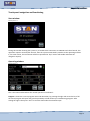
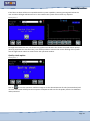
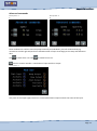
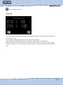
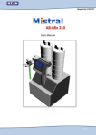
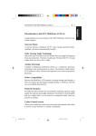
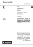
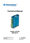
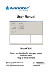
® STAN Engineering aCCura Mix-VI control Installation and service manual Page 1 Summary INTRODUCTION ................................................................................................................................................. 3 Use compliance ................................................................................................................................................. 4 Safety instructions ............................................................................................................................................. 5 Connections ....................................................................................................................................................... 6 Motor drives .................................................................................................................................................. 6 Touch panel ................................................................................................................................................... 6 Signal connection X1.................................................................................................................................. 7 Touch panel navigation and functioning ........................................................................................................... 8 Start window ................................................................................................................................................. 8 Operating window ......................................................................................................................................... 8 Quality check option.................................................................................................................................... 10 Menu ........................................................................................................................................................... 11 Alarm ........................................................................................................................................................... 11 Advanced commands .................................................................................................................................. 12 Calibration ................................................................................................................................................... 13 Options ........................................................................................................................................................ 14 Settings ........................................................................................................................................................ 15 Security ........................................................................................................................................................ 15 Page 2 INTRODUCTION Dear ladies and gentlemen! First of all, we would like to gratulate you for buying Stan Engineering® products, allowing you to work with the latest technology. To be able to avoid malfunctions, some important criteria now follows for commissioning your Stan engineering® product and the servicing afterwards. Furthermore, we see it as our utmost duty to inform you about possible dangers in accordance with the operation of your new pump and controller. Therefore, please note, that this manual needs to be within the near of your service and other related personnel during, before and after operation of the controller. We emphasize the need for reading this manual carefully and would like to point out, that important notices relating your security will follow within the next pages of this manual. Understanding all notices and the technology related information allow you to operate your latest Stan Engineering® product without endangering yourself and others. We wish you success and all the best with your newest Stan Engineering® product. The Stan Engineering® team Page 3 off 15 Page 3 Use compliance Before operation, please carefully read the following : Do not use within EX-zones! Do not use in wet or moisture rooms! Temperature: +10°C till +40°C (50°F till 104°F) Avoid high frequency transmitters or rooms Do not spill fluids over it nor put it under water or any kind of fluid! 1. Please intensively study this manual before commissioning. Do get familiar with the operation manual before each start of the pump or every time when the operator changes. 2. Please note, that this manual is part of this particular pump even when being moved to another department or company. 3. The pump may only be used by healthy people 4. Do only use Stan Engineering® spare parts. Damages caused by using other parts are not supported by the Stan engineering ® warranty. 5. Should any of this manual not be clear or understandable, pleased do contact your distributor or write us under [email protected]. Do not use with materials that can gas out or react with gas. Please do contact your distributor for further information. Any improper use will produce the loss of the support of the Stan Engineering® warranty. Explicit compliance for the pumped material: Depending on the application, the maximum environmental temperature may not succeed 40°C. With the use of aggressive products, please do always contact your distributor and product supplier to get approval before operation and or commissioning. Make sure, that the local legislation has been incorporated all safety relevant demands are being kept. Changes done by the user result in loss of warranty. All damage claims upon will be ignored. All safety relevant technical issues lose the Stan Engineering® warranty support. This sign shows a safety relevant message. Make sure all operator personnel and safety people take note or have been made aware. All rights reserved. This manual may not be duplicated without written agreement of the manufacturer. Page 4 Safety instructions Make sure, that you have taken care of the rules for accident prevention next to reading this manual. Do not disregard any caution sign; they give important notices to prevent accidents or injuries. Caution signs are an important part of the safety rules for accident prevention therefore need to be visible at l times. Before commissioning, please do check all connections and see if they are well tightened, pushedin and assembled. Before starting to work with the pump, every worker needs to fully understand the application and its demands. Service and repairs may only be performed via trained personnel and the relevant tools. All needed accident prevention apparatus and fixtures must be installed before operation. Make sure they are in good condition at all times. Do only service the controller when the motor and power cable have been disconnected. In case solvents are used, it may be needed to wear breathing protection masks. Please ask your safety staff. Do not use in EX-zones This technical manual is intended for designers and developers who lack extensive experience with stepper/brushless motor technology but who need to commission the motor. This technical manual must be carefully read before installing and commissioning the controller. In the interests of its customers and to improve the function of this product. This manual was created with due care. It is exclusively intended as a technical description of the product and as commissioning instructions. The warranty is exclusively for repair or replacement of defective equipment, according to our general terms and conditions; liability for subsequent damage or errors is excluded. Applicable standards and regulations must be complied with during installation of the device. Page 5 Connections Your aCCuraMix-VI is composed by 2 Nanotec SMCI36 boards and 1 Pro-face LT-4201TM touch panel used for the user interface (HMI), the devices communicate via CAN-Bus net where the panel is the master and the 3 driver are slaves. A switching 24Vdc power supply is also inside the aCCuraMix-VI Electric connections : n.2 Motor connections n.2 Hall sensor connections n.1 Power supply n.1 IN/OUT socket used for : - external IN start/stop - ready OUT signal - run OUT signal - alarm OUT signal - external OUT signal 24Vdc Motor drives This is an example of the Nanotec PC board integrated in the aCCuraMix-VI. The Essential features are just an extract of the original Nanotec properties. Go to ww.nanotec.de or www.nanotec.com for more information. For further information please read the ‘SMCI36_Technical-Manual.pdf’ and NanoCAN SW Manual. Touch panel This is an example of the Proface touch panel integrated in the aCCuraMix-VI. The Essential features are just an extract of the original Nanotec properties. Go to www.pro-face.com for more information. For further information please read the ‘LT4243TM-MM01-ENG-PDF.pdf’. Page 6 Signal connection X1 The aCCuraMix-VI is equipped of an external terminal for external signals exchange 1 2 3 4 5 6 7 8 9 10 24 Vdc Gnd IN1 + (Filter 0.5 ms...30.0 ms) IN1 OUT1+ OUT2+ OUT3+ available available available IMPORTANT NOTICE: Please note, that the NanoCan and GP-Pro EX Software have been adapted to the needs of STAN Engineering aCCura series pumps. Some features have been changed in order to perform easy dispensing. Therefore, you receive a pre-set configuration. Page 7 Touch panel navigation and functioning Start window Security level : 0 During this window showing the system try to establish the connection via CAN-Bus with the 2 boards, this operation requires normally few seconds, then the system automatically switches to the operating window. If, for some reason, the connection will be not possible the ‘skip’ button will enable and allow the navigation anyway. Operating window Security level : 0 This is the main window where the normal operation are allowed : Program : shows the current program name and ID number, by pressing the right side arrow the list of all the stored program will open and give the possibility to load another pre-saved dosing program. After setting the right values press ‘save’ to store the data under the selected recipe. Page 8 Security level : 0 From this window is possible to manage recipes : Loads the selected recipe on the working data Create a copy of the selected recipe Edit the name of the recipe Delete the selected recipe Press ‘close’ to come back. Ratio : set and shows the desired ratio between A component and B component, this ratio can be referred to the volume or weight (see the Option page parameters) Waiting time : this parameter define the time (mSecs) between the dispensing and the suck-back operation (if needed). Time : set and shows the duration of one dispensing and suck-back cycle Flow-rate : set and shows the flow-rate of the product during the dosing cycle and the speed to be used for the suck-back Quantity : set and shows the amount of product to dispense during the dosing cycle and the degrees to perform during the suck back The HMI software allows the user to introduce one of the 3 parameter according to the needs of the application. So one of the 3 will be ‘frozen’ (by directly clicking on the labels). The frozen data will appear grey, the others yellow. By changing one parameter, the frozen will remain the same and the other one will change accordingly. Page 9 If the flow-rate data will be not compatible with the system capability a warning message will advise the user and the trafficlight will become red. In this conditio the system will not allow any dispense. Security level : 0 Through this window the user can access to a graphical visualization that shows the speed of both pumps (directly proportional to the flow-rate), so it will be possible to monitor the correct working of the system. Use the right bottom switch to came back to the operation window. Quality check option Security level : 1 Click on to start the operation. Will be enough to set the desired amount of trials (retentive data) and once the ‘ok’ button will be pressed a sequence of dispenses will start for the quality check. This window is under password. Page 10 Menu Security level : 0 This is the general menu where all the configuration and advanced options are available (under the right security access level). Click on the icon or on the labels to access to the relative windows. Alarm Security level : 0 This window will appear automatically when an alarm will occur, press and in order to start any operation . to stop. Reset alarms Acknowledge alarms Clean the list Historical alarm list Page 11 Advanced commands Security level : 2 Security level : 2 1 2 These windows are useful to start the pumps manually and individually, the left window allows jog movements and the right will perform a defined number of steps accordingly to the setup and calibration data. Use to switch from 1 to 2 and to switch from 2 to 1. switch to monitor window : visualization of input and force output Security level : 2 Just press on the output (right) buttons to activate/deactivate outputs and see the status of the input. Page 12 switch to calibration window Calibration Security level : 2 From this window is possible to set the K-factor for A and B component. How must be set those factors ? The procedure is easy : Be sure that the settings configuration is correct (see settings chapter) Start a dosage of a known quantity from the advanced command page, for example 50 cc Weight the amount actually dispensed, for example 51 g, then convert it in volume through its specific gravity, for example 1 so 51 cc. At this point just input under the relative component the Factor (51/50 = 1.02). Page 13 Options Security level : 2 From this window the user can : change the application language Set the specific gravity of the products Set the inactivity time (sec.): if different from 0 it deactivate the power from the pumps after the expiration of the time, the following message will be shown. Once pressed the ok button the current will be restored (if a start signal is given the current will be automatically restored). Page 14 Settings Security level : 3 This window allow the configuration of the system. The possibility are : A:aCCura01 B:aCCura01 A:aCCura01 B:aCCura02 A:aCCura02 B:aCCura01 A:aCCura02 B:aCCura02 IMPORTANT : do not change the value of the parameters if you don’t know very well the system. Security Security level : 0 From this window the login management and the change of the password is possible. The application uses 3 levels. Here following the default password for the security levels : Level 1 Id : QC pwd : QC Level 2 Id : TECH pwd : TECH Level 3 Id : A pwd : A Page 15