1
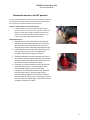
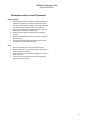
Thermostat, RF103
Thermostat - Description
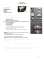
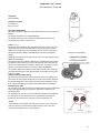
Thermostat
IFS Part # 37012
Component Location
Bunk, above Bed, Side wall or closet
Description and Application
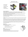
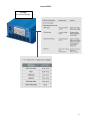
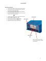
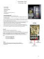
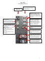
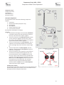
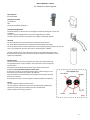
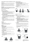
The Idle Free Thermostat contains a LCD display and two Slide Switches.
The IFS Thermostat uses two AA Batteries to power the display and to send switch signals to the Idle Free Relay Group
(RF106).
The left slide switch is used to turn on the air conditioner or turn on the heat. The center position of the left slide switch
turns the system OFF.
The right slide switch has two positions marked AUTO & ON.
The AUTO position is used if the system user wishes to have the air conditioner’s evaporator fan turn on and off with the air
conditioning compressor circuit. Leaving this switch in the ON position will continuously run the evaporator fan regardless
of the compressor’s current mode.
The driver should place the Fan Switch in the ON position for best system performance. Placing the Thermostat Fan switch
in the ON position will eliminate 10% of the Inverter start up power needs.
The IFS Thermostat has two soft push buttons located under the LCD Display.
The center soft button is used to display the current room temperature and turn on the display’s backlight.
The right soft switch increases the temperature setting of the thermostat and the left soft button decreases the
temperature of the room setting.
A low Voltage Battery Indicator Icon is shown on the display when the AA batteries need to be changed.
HEAT MODE
The thermostat is used to turn on the Idle Free water heater and the Heat relay (Relay Group RF106).
The thermostat when in HEAT Mode provides 12VDC power to the Truck’s Bunk Blower fan, The Thermostat’s temperature
settings are not used in Heat Mode, The truck’s bunk controls are used to provide Bunk Heat temperature control.
Technical Information
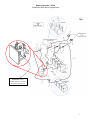
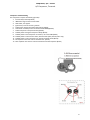
The Idle Free Thermostat can be separated from its mounting base.
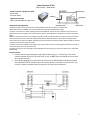
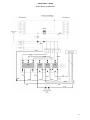
The mounting base contains terminals for the wiring harness the runs between the thermostat and the UBB (REF Sheet
#63110).
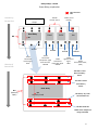
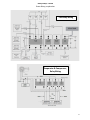
The Thermostat is used to operate the Relay Group located in the UBB (RF106).
The Thermostat is supplied with 12VDC Power from the 2AMP fuse located on the front of the UBB (RF108).
The 12 VDC power enters the thermostat base on the red wire, R terminal (Jumped) to a second R marked terminal.
The thermostat switch positions determine where, how and when 12VDC power is sent to the UBB Relay Group.
• G Terminal - Green wire; 12VDC to the Evaporator Relay
• Y Terminal - Yellow Wire; 12 VDC to the Compressor Relay
• B terminal – Blue Wire; 12VDC to the Heat Relay
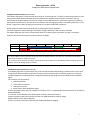
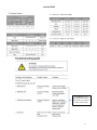
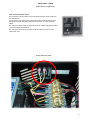
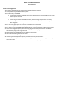
The back side of the Thermostat includes 3 DIP switches that need to be in the proper position for the Thermostat to
Function Properly
1. CONV/HP = HP
2. F/C = F
3. HE/HG = HG
Common Failure Issues
User fails to understand that the left Mode switch in A/C mode has a 5 minute delay between ON then OFF then
ON. This causes confusion and is dealt with by instructing the driver to place right switch in the auto position to see
if the Thermostat is in the 5 minute delay window. If the evaporator fan is not running when the Mode switch is in
COOL mode, the thermostat is in the 5 minute delay mode.
Drivers need to operate the Thermostat with the Fan Switch in the ON position. The ON position eliminates the
need to start the Evaporator Blower fan and the compressor at the same time.
7