1
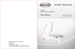
To request service, refer to the user’s manual.
If failure or damage occurs after referring to the manual,
stop using and contact the retailer for service.
User Manual
User Manual
Contents
Parts·······························································03
Installation·····················································05
Operation·······················································08
Cleaning and Removal·································09
Maintenance··················································10
Troubleshooting & Specifications···············11
Parts
Product
Water inlet
Removal
button
Seat cover
Water tank
Lever
Seat
T-shaped connector
Bidet nozzle
Wash nozzle
Water supply hose
Bowl
Shut-off valve
Water inlet hose
03
Components
1. Main body
2. Installation Template
3. Hardware
Connecting bolts (2)
Expanding Nuts (2)
Bracket
Sliding plates (2)
4. T-shaped connector
Wing Nuts (2)
5. Water hose
6. User Manual
User Manual
Filter
Note
04
There are two installation methods. You may use expanding nuts or wing nuts.
Installation
* Please make sure you read the instructions carefully and install it properly.
1. Insert the connecting bolts into sliding plates.
2. Insert the connecting bolts with sliding plates into the bracket.
The water pressure range for this product is 10 - 115 PSI (0.07 - 0.8 MPa).
Caution
05
Installation Method A (recommended)
1. Loosen nuts and remove the old seat and seat lid.
2. Insert expanding nuts into the toilet bowl holes.
Seat and seat lid
3. Place installation template onto toilet bowl.
4. Place bracket onto toilet bowl and screw connecting
bolts into expanding nuts. Be sure to keep the side
with ‘FRONT’ up.
Bracket
Installation
template
Installation
template
Wing nuts are used for
Installation Method B.
5. Remove the installation template.
6. Slide product onto toilet as shown in the figure.
Installation
template
Installation Method B
1. Refer to steps 1 and 3 of Installation Method A. Do not install expanding nuts.
2. Refer to step 4 of Installation Method A, but secure panel with wing nuts instead of expanding nuts.
3. Refer to steps 5 and 6 of Installation Method A to complete installation.
06
Connecting the water hose
1. Close the shut-off valve and detach the water hose from the toilet tank.
Connect the T-shaped connector to the water tank. Make sure the rubber
washer is in place.
2. Connect the water supply hose to the T-shaped connector.
You may remove the water regulator cover and regulator O-ring if the water pressure of the product is too low.
See figure.
Note
1. Remove the regulator component with pliers.
2. Remove the regulator cover and regulator O-ring, but leave the remaining parts.
3. Reinsert the remaining regulator component (without the cover and O-ring) into the inlet pipe of seat.
Caution
You must use the regulator cover and O-ring when the water pressure is greater than 15 PSI.
1
Regulator
2
Regulator
O-ring
Sealing
O-ring
3
Regulator
cover
3. Connect the main body to the T-shaped connector
using the supplied water hose. Make sure filter and
rubber washers remain in water hose.
4. Open the shut-off valve to check for leakage.
Washer
Filter
1. Do not lift the product with the seat cover and seat open. You may damage the product.
2. The water supply must be between 32°F and 105°F (0°F - 40°C).
Caution
07
Operation
Wash
Low flow
Turn the lever clockwise. The wash
nozzle will move forward and begin
washing.
High flow
Low flow
Bidet
Turn the lever counterclockwise.
The bidet nozzle will move forward
and start washing.
High flow
Off &
Self-Cleaning
Off : Keep the lever vertical.
Self-Cleaning : Hold the lever at 25°
for a few seconds.
Note Nozzles automatically clean
themselves after each use.
08
25º
90º
25º
Cleaning & Removal
1. Cleaning the ouside of the product
Use a smooth sponge/cloth with diluted kitchen
detergent.
2. Cleaning the nozzles
Pull out the nozzles gently and use a smooth cloth/
sponge or your friend’s toothbrush with kitchen
detergent to clean the nozzles.
Paint
thinner
Insecticide
Abrasive
paper
3. Cleaning the filter and regulator
Note
Do this if the flow is lower than usual.
1. Clean the filters on both sides.
2. Clean the regulator O-ring. (See page 10 to find
out how to remove regulator.)
4. Removing the main body
Close the lid. Push the removal button and pull out
product as shown in the figure.
Hose
* Removal button
Filter
regulator
O-ring
09
Maintenance
1. Lever Replacement
2. Nozzle Replacement
Remove the lever along the axis as shown in the
figure. Install a new lever by pushing it in. You should
hear a ‘click’ sound.
B
A
Nozzle
3. Regulator Replacement
Rotate the lever to working position (wash or bidet).
Pull out regulator from the inlet pipe using pliers.
Push the new regulator into the inlet pipe. Rotate the
lever to non-working position (off).
Regulator
10
Pull out the tube gently and don’t release. Remove
the old nozzle along the axis as shown. Insert a
new nozzle.
A
B
4. Leakage
If water leaks from the two ends of the water hose,
re-tighten the nuts. Do not over-tighten.
Troubleshooting & Specifications
Troubleshooting
Problem
Cause
Solution
Turn lever to maximum flow
Water flow is low while using
Water is dripping while using
Low water pressure of the unit
Remove regulator cap and O-ring. Refer to manual for
instructions
Low water pressure of water supply
Contact local water department
Water shut-off valve is closed
Open shut-off valve
Filter of T-shaped connector is clogged
Clean the filter
Filter of water inlet hose is clogged
Clean the filter
Nozzle head is stuck
Clean the nozzle head
External water pressure is low
Increase external water pressure
External water pressure is too big
The maximum water pressure of the unit is 115 PSI (0.8
Mpa). If water pressure is higher, please contact local
water department.
Do not disassemble or repair the unit.
Caution
Specifications
Water Flow
Water Pressure Range
Backflow Prevention
Dimensions
Weight
0.09 – 0.48 gallons/min (0.35 – 1.8 L/min)
Static Pressure: 10-115 psi (0.07-0.8MPa)
Dynamic Pressure: above 5 psi (0.03 MPa)
Check valve, vacuum breaker
14.6x19.7x2.5 inches (370x500x62mm)
4.6 lbs (2.09 kg)
11