1
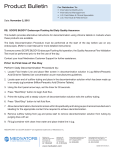
LBS
USER MANUAL
LMI Sensors-95
Valkenburgerweg 223
6419 AT HEERLEN
The Netherlands
Telephone
: +31 (0) 45 5719300
Fax
: +31 (0) 45 5742500
Serial number : _ _ B04_ _ _
SAFETY REGULATIONS
The "LXS-range" from LMI Sensors-95 are precision instruments in which a semi-conductor laser is being
used as a light source.
Power :
Spectrum:
5 mWatt
670 nm, visible red light
According to the European Safetynorm the laserdiode is classified in classe IIIa.
Do not point the sensor at any person.
Labels
The following labels must always be shown perceptible on the lasersensor (if not possible: in the direct
surrounding).
Standard, the sensors have been supplied for the required labels by LMI Sensors-95.
-
Standard Laser Symbol
-
Classification laser
General
The producer and supplier are not responsible for damage, which is caused by inexpert use and/or faulty
working of the sensor.
In connection with safety reasons the lasersensor only needs to be installed and maintained by authorized
personnel. In cause of malfunction, please contact LMI Sensors-95.
INSTALLATION
When installing the "Laser Beam Sensor" you need to take the following items into account:
-
During assembling and maintenance the sensor needs to be switched off. This to prevent
somebody looks into the laserbeam per mistake.
A non-solid attachment of the sensor will effect the measurement negatively.
In spite of the sensor housing being extremely robust and the electronics, optics and
laser being
protected in this way, you need to take into account that vibrations c.q. Resonances
in the system can
cause undesirable measuring faults.
Since this is an "optical system" you need to prevent the lenses to get dirty. This has a negative
effect on the measurement.
The cleaning of the lenses needs to take place with a suitable means for that (for example
optical cleaning cloth).
A clean environment is recommended. Smoke and dirt can influence the laserbeam.
The maximum temperature on which the semi-conductor laser may be exposed, amounts to
50°C.
Avoid direct radiation from sunlight.
LBS
-
Place the transmitter and the receiver in line.
For the connections of the sensors see chapter Connections.
Switch on the system and reckon with the warming-up time.
With the potentiometer on the receiver you can adjust the amplification factor.
Notice the following steps :
-
Receiving no laser light
Output voltage 0Volt.
Receiving 100% laser light
Output voltage 10Volt
Adjust the output voltage (10Vdc) with the potentiometer.
Connections
N.B.
Transmitter:
brown
black/green
+15 to +30 Vdc
GND
Receiver:
brown
black/green
yellow
+15 to +30 Vdc
GND
OUTPUT
-
Only use a linear powersupply !!!
Make sure the positive and negative supply-voltage is present at the same time !!!
Warming-up time
Please reckon with a warming-up time of ± 10 minutes.
Specifications
Laserbeam
Accuracy
(*)
resolution
(*)
Measuring frequency
Modulation frequency
Temperature range
Humidity
Output
Power supply
Power consumption
Laserdiode
*
Resolution and accuracy depend of measuring-range.
B x A in mm
>0.005 / 0.12 mm
>0.001 / 0.024 mm
1 kHz (optional 10kHz)
50 kHz
0 - 50°C
max 90%
0-10 Vdc
Rload> 4k7Ù
15 - 30 Vdc
max. 5W
5mW (655nm)
DIMENSIONS
Transmitter
Receiver
Fastening screw thread: M4