1
User Manual for the
CBREEZE Software
HE500TSW232
Operator Station
Tenth Edition
6 APR 2002
MAN0023-10
PREFACE
6 APR 2002
PAGE 3
MAN0023-10
PREFACE
This manual explains how to use the Horner APG Operator Station products and CBREEZE software.
Copyright © 2001 Horner APG, LLC., 640 North Sherman Drive, Indianapolis, Indiana 46201-3899. All
rights reserved. No part of this publication may be reproduced, transmitted, transcribed, stored in a
retrieval system, or translated into any language or computer language, in any form by any means,
electronic, mechanical, magnetic, optical, chemical, manual or otherwise, without the prior agreement and
written permission of Horner APG, LLC.
Information in this document is subject to change without notice and does not represent a commitment on
the part of Horner APG, LLC.
Windows 95 , Windows 98 , and Windows NT are registered trademarks of Microsoft Corporation.
DeviceNet is a trademark of Open DeviceNet Vendors Association (ODVA).
Profibus is a trademark of Siemens.
Cscape, CsCAN, and SmartStack are trademarks of Horner APG, LLC.
For user manual updates, contact Horner APG, Technical Support
Division, at (317) 916-4274 (USA), or +353-21-4321266 (Europe) or visit
our web-site at www.horner-apg.com.
LIMITED WARRANTY AND LIMITATION OF LIABILITY
Horner APG, LLC. ("HE-APG") warrants to the original purchaser that the Operator Station manufactured by HE is free from defects
in material and workmanship under normal use and service. The obligation of HE-APG under this warranty shall be limited to the
repair or exchange of any part or parts which may prove defective under normal use and service within two (2) years from the date
of manufacture or eighteen (18) months from the date of installation by the original purchaser whichever occurs first, such defect to
be disclosed to the satisfaction of HE-APG after examination by HE-APG of the allegedly defective part or parts. THIS WARRANTY
IS EXPRESSLY IN LIEU OF ALL OTHER WARRANTIES EXPRESSED OR IMPLIED INCLUDING THE WARRANTIES OF
MERCHANTABILITY AND FITNESS FOR USE AND OF ALL OTHER OBLIGATIONS OR LIABILITIES AND HE-APG NEITHER
ASSUMES, NOR AUTHORIZES ANY OTHER PERSON TO ASSUME FOR HE-APG, ANY OTHER LIABILITY IN CONNECTION
WITH THE SALE OF THE Operator Station. THIS WARRANTY SHALL NOT APPLY TO THE Operator Station OR ANY PART
THEREOF WHICH HAS BEEN SUBJECT TO ACCIDENT, NEGLIGENCE, ALTERATION, ABUSE, OR MISUSE. HE MAKES NO
WARRANTY WHATSOEVER IN RESPECT TO ACCESSORIES OR PARTS NOT SUPPLIED BY HE. THE TERM "ORIGINAL
PURCHASER", AS USED IN THIS WARRANTY, SHALL BE DEEMED TO MEAN THAT PERSON FOR WHOM THE Operator
Station IS ORIGINALLY INSTALLED. THIS WARRANTY SHALL APPLY ONLY WITHIN THE BOUNDARIES OF THE
CONTINENTAL UNITED STATES.
In no event, whether as a result of breach of contract, warranty, tort (including negligence) or otherwise, shall HE-APG or its
suppliers be liable of any special, consequential, incidental or penal damages including, but not limited to, loss of profit or revenues,
loss of use of the products or any associated equipment, damage to associated equipment, cost of capital, cost of substitute
products, facilities, services or replacement power, down time costs, or claims of original purchaser's customers for such damages.
To obtain warranty service, return the product to your distributor with a description of the problem, proof
of purchase, post paid, insured and in a suitable package.
PAGE 4
MAN0023-10
6 APR 2002
PREFACE
ABOUT PROGRAMMING EXAMPLES
Any example programs and program segments in this manual or provided on accompanying diskettes are
included solely for illustrative purposes. Due to the many variables and requirements associated with any
particular installation, Horner APG, LLC cannot assume responsibility or liability for actual use based on
the examples and diagrams. It is the sole responsibility of the system designer utilising the Operator
Station to appropriately design the end system, to appropriately integrate the Operator Station and to
make safety provisions for the end equipment as is usual and customary in industrial applications as
defined in any codes or standards which apply.
NOTE: The programming examples shown in this manual are illustrative
only. Proper machine operation is the sole responsibility of the system
integrator.
DECLARATION OF EMC CONFORMITY
Manufacturer's Name:
Manufacturer's Address:
Horner Ireland Ltd.
Unit 1, Centrepoint, Centre Park Road, Cork, Ireland
Declares that the products
Models: HE500TIU050, HE500TIU100, HE500TIU101, HE500TIU110,
HE500TIU111, HE500TIU200 and HE500TIU201
Conforms to the following EMC standards:
EMC:
EN 55 022, Radiated and Conducted Emissions
EN 50 082-1, RF, EFT/EFB, ESD Immunity
Supplementary Information:
The above conformity only relates to the products in a stand-alone capacity. The products are used as
part of a system and are therefore classified as a component. As a component, the products are
prohibited by EC regulations to carry a CE Mark for EMC conformity. Static discharge tests only apply to
normal operation of the keyboards via the front panel. We would stress that the use of our products
within your system, while helping to ensure compliance of your system to the same directives, do not
necessarily guarantee that compliance will be achieved. We would also like to point out that the
interpretation of the law concerning CE marking and its application to sub-assemblies and components is
open to interpretation.
Date: 31 Mar 1999
PREFACE
6 APR 2002
PAGE 5
MAN0023-10
REVISIONS TO THIS MANUAL
This version (MAN0023-10) of the CBREEZE software for the Tiu Range contains the following revisions,
additions or deletions:
Figure 8.1 Replaced Old Shapes Tool bar with new Shapes Toolbar
Modified Section 8.2.2 Rectangle to encompass new shape colour control box
Subsection 8.2.7 Inserted new shapes mode ‘Bezel Mode’
Subsection 8.2.8 Added information on solour control techniques for text objects
Subsection 8.2.9 Ínserted new shapes mode ‘Touch Key Mode’
Subsection 8.2.10 Removed references to old bitmap editor
Subsection 8.2.12 Flood Fill Mode Added.
Inserted Section 8.3 Palette Toolbars.
Replaced Figure 8.8 with current animation toolbar
Moved section 8.4.2 Animated bitmap Selectors to fall in line with numbering for other embedded types.
Added Section 8.4.4 Lamps
Added Section 8.4.5 Switches
Added Section 8.4.6 Sliders
Added Section 8.4.7 Curved Analogue Fills
Added Section 8.4.8 Object Groups
Added Section 8.4.9 The Part Library
Added Section 8.4.10 The NotePad Object
Added Section 8.4.11 Multipen Trends
Reworded much of section 8.5 Animated bitmap editor.
Modified Section 8.6 Draw Attributes to reflect new palette styles for Tiu300 series
Added Section 8.7 Paste Options.
Added Section 8.8 Auto Adjust Size
Inserted sections 9.2 Modbus, and 9.3 Serial CsCan
Added Chapter 12 The Report Generator
PAGE 6
MAN0023-10
6 APR 2002
PREFACE
TABLE OF CONTENTS
PREFACE ............................................................................................................................................... 3
LIMITED WARRANTY AND LIMITATION OF LIABILITY.......................................................................... 3
ABOUT PROGRAMMING EXAMPLES .................................................................................................... 4
DECLARATION OF EMC CONFORMITY ................................................................................................ 4
REVISIONS TO THIS MANUAL............................................................................................................... 5
CHAPTER 1: INTRODUCTION.............................................................................................................. 11
1.1
Scope....................................................................................................................................11
1.2
Equipment Needed................................................................................................................11
1.3
Upgrade Revision Software & Firmware ................................................................................11
1.3.1
General ..............................................................................................................................11
1.3.2
Software Upgrade ...............................................................................................................11
1.3.3
Firmware Upgrade ..............................................................................................................11
CHAPTER 2: GETTING STARTED........................................................................................................ 13
2.1
Self-Test................................................................................................................................13
2.2
Contrast Band .......................................................................................................................13
2.3
Display Test ..........................................................................................................................13
2.4
Keyboard Test.......................................................................................................................13
2.5
RAM Test ..............................................................................................................................13
2.6
Serial Loop-back Tests ..........................................................................................................13
2.7
Selecting the Automation Equipment (AE) .............................................................................14
2.8
Proving Communications.......................................................................................................16
2.9
Icon Descriptions...................................................................................................................17
2.10
Up/Down Keys.......................................................................................................................18
2.11
Key Symbols .........................................................................................................................18
CHAPTER 3: ABOUT PROJECTS......................................................................................................... 19
3.1
Scope....................................................................................................................................19
3.2
About TIU Terminal ...............................................................................................................19
3.3
Creating a New Project..........................................................................................................19
3.4
Opening a Project..................................................................................................................20
3.5
Saving a Project ....................................................................................................................20
3.6
Downloading a Project...........................................................................................................20
3.7
Uploading a Project ...............................................................................................................20
3.8
Verifying a Project .................................................................................................................20
3.9
Updating the Protocol ............................................................................................................21
3.10
Updating the Operating System .............................................................................................21
3.11
Printing..................................................................................................................................22
3.12
To Insert a New Page............................................................................................................22
3.13
Default Page Type.................................................................................................................22
3.14
Download/Upload Character Set (Not available with the HE500TIU050) ............................................23
3.14.1 To Download a Character Set: ...........................................................................................23
3.14.2 To Upload a Character set from the TIU: ............................................................................23
3.15
Select Terminal Type.............................................................................................................23
3.15.1 To select the Operator Station Terminal Type: ....................................................................23
3.16
Delete a Page .......................................................................................................................23
3.17
Font Size (Not available with the HE500TIU050)....................................................................23
3.17.1 To change/set the Font Size of a line: .................................................................................23
3.18
Key Mapping .........................................................................................................................23
3.18.1 To enable key mapping:......................................................................................................24
3.19
Function Keys .......................................................................................................................24
3.19.1 Function Key LEDs on HE500TIU20X .................................................................................27
CHAPTER 4: EMBEDDED DATA .......................................................................................................... 29
4.1
Scope....................................................................................................................................29
PREFACE
6 APR 2002
PAGE 7
MAN0023-10
4.2
Numeric Data ........................................................................................................................30
4.2.1
Scope .................................................................................................................................30
4.2.2
To edit numeric data: ..........................................................................................................31
4.2.3
To change data registers contents from the HE500TIU050/10X/11X/20X: ...........................31
4.3
Alphanumeric Data................................................................................................................31
4.3.1
Scope .................................................................................................................................31
4.3.2
To embed alphanumeric data:.............................................................................................32
4.4
Timers...................................................................................................................................32
4.4.1
Scope .................................................................................................................................32
4.4.2
To monitor Timers on the HE500TIU050/10X/11X/20X........................................................33
4.4.3
To edit the data field: ..........................................................................................................33
4.5
Bit Status...............................................................................................................................33
4.5.1
Scope .................................................................................................................................33
4.5.2
To select the data field for editing:.......................................................................................34
4.6
System Variables ..................................................................................................................35
4.6.1
Scope .................................................................................................................................35
4.7
Passwords.............................................................................................................................35
4.7.1
Scope .................................................................................................................................35
4.7.2
To password protect a sub-menu: .......................................................................................35
4.7.3
To enter the password from the HE500TIU050/10X/11X/20X: .............................................36
4.8
Analog Meters .......................................................................................................................37
4.8.1
Scope .................................................................................................................................37
4.9
Text Selector .........................................................................................................................38
4.9.1
Scope .................................................................................................................................38
4.9.2
Edit Text Tables..................................................................................................................38
4.9.3
To Add an Table Entry ........................................................................................................39
4.9.4
To edit a text table from the HE500TIU050/10X/11X/20X: ...................................................40
4.9.5
To Export/Import a Text Table.............................................................................................40
4.9.6
Auto Mask Bit .....................................................................................................................40
4.9.7
Default Text Table Entries...................................................................................................40
4.10
Clock Calendar......................................................................................................................41
4.10.1 Scope .................................................................................................................................41
4.10.2 Clock Calendar Mapping.....................................................................................................42
4.11
Menu Timeout .......................................................................................................................43
4.11.1 Scope .................................................................................................................................43
4.12
Flashing Characters ..............................................................................................................44
4.12.1 Scope .................................................................................................................................44
4.13
Set the Real-time Clock.........................................................................................................44
4.13.1 Scope .................................................................................................................................44
4.14
Scaling ..................................................................................................................................44
4.14.1 Scope .................................................................................................................................44
4.14.2 To enable Scaling: ..............................................................................................................44
4.15
Page Wizard..........................................................................................................................45
4.15.1 Scope .................................................................................................................................45
4.15.2 To use the Page Wizard:.....................................................................................................45
4.16
Graphing (Not available with the HE500TIU050)....................................................................45
4.16.1 Scope .................................................................................................................................45
4.16.2 To Embed a Graph: ............................................................................................................46
4.16.3 Enable Axes .......................................................................................................................47
4.17
Trending (Not available with the HE500TIU050) ....................................................................47
4.17.1 Scope .................................................................................................................................47
4.17.2 Enable Axes .......................................................................................................................47
4.17.3 Data Indirectly Specified. ....................................................................................................48
4.17.4 Control Data from Remote Device.......................................................................................48
4.17.5 To Embed a Trend..............................................................................................................48
CHAPTER 5: CHARACTER GENERATOR............................................................................................ 49
PAGE 8
MAN0023-10
6 APR 2002
PREFACE
5.1
Scope (Not available on the HE500TIU050)...........................................................................49
5.2
To Insert a Special Character: ...............................................................................................49
5.3
To Create Or Edit a Character: ..............................................................................................50
5.4
International Keyboards.........................................................................................................51
CHAPTER 6: RECIPES ......................................................................................................................... 53
6.1
Scope....................................................................................................................................53
6.2
To Enable Recipes: ...............................................................................................................53
6.3
To Edit Recipe Fields and Records:.......................................................................................53
6.4
Editing Ingredient Properties..................................................................................................54
6.5
To Edit Recipe Data ..............................................................................................................55
6.6
To Rename a Record ............................................................................................................55
6.7
To Embed a Recipe on a Menu Page ....................................................................................56
6.8
Importing and Exporting Data from a Recipe:.........................................................................57
CHAPTER 7: TUTORIAL ....................................................................................................................... 59
7.1
Scope....................................................................................................................................59
7.2
Menus ...................................................................................................................................59
7.3
Sub-Menus............................................................................................................................62
7.3.1
To Enter A Sub-Menu On the HE500TIU050/10X/11X/20X:.................................................64
7.4
Password-Protected Sub-Menus............................................................................................65
7.4.1
Scope .................................................................................................................................65
7.4.2
To Enter the Sub-Menu:......................................................................................................66
7.4.3
To Edit The data On The Sub-Menu Pages:........................................................................66
7.5
Status....................................................................................................................................67
7.5.1
Scope .................................................................................................................................67
7.6
Alarms...................................................................................................................................71
7.6.1
Scope .................................................................................................................................71
CHAPTER 8: GRAPHIC EDITOR .......................................................................................................... 75
8.1
Scope....................................................................................................................................75
8.2
Draw Mode............................................................................................................................75
8.2.1
Selector ..............................................................................................................................75
8.2.2
Rectangle ...........................................................................................................................75
8.2.3
Ellipse.................................................................................................................................77
8.2.4
Rectangle with Round Corners............................................................................................77
8.2.5
Lines...................................................................................................................................77
8.2.6
Arcs ....................................................................................................................................77
8.2.7
Bezel Mode.........................................................................................................................77
8.2.8
Text Mode ..........................................................................................................................78
8.2.9
Static Bitmap ......................................................................................................................80
8.2.10 Table Mode.........................................................................................................................80
8.2.11 Touch Key Mode.................................................................................................................81
8.2.12 Flood Fill Mode ...................................................................................................................81
8.3
Palette Toolbars ....................................................................................................................82
8.3.1
Scope .................................................................................... Error! Bookmark not defined.
8.4
Embedding Data on a Graphic Menu Page ............................................................................83
8.4.1
Scope .................................................................................................................................83
8.4.2
Analogue Meter ..................................................................................................................83
8.4.3
Animated Bitmap Selector...................................................................................................84
8.4.4
Lamp ..................................................................................................................................84
8.4.5
Switch.................................................................................................................................86
8.4.6
Sliders ................................................................................................................................86
8.4.7
Curved Analogue Fills.........................................................................................................87
8.4.8
Object Groups.....................................................................................................................88
8.4.9
The Part Library..................................................................................................................89
8.4.10 The Note Pad Object ..........................................................................................................90
8.4.11 Multipen Trends ..................................................................................................................90
8.5
Creating Animated Bit Maps ..................................................................................................91
PREFACE
6 APR 2002
PAGE 9
MAN0023-10
8.5.1
Scope .................................................................................................................................91
8.5.2
To change the bitmap selected from graphics terminals without a touch screen...................91
8.5.3
To change the bitmap selected from graphics terminals with a touch screen. ......................92
8.5.4
Creating a new animated bitmap.........................................................................................92
8.5.5
The Animated Bitmap Editor ...............................................................................................93
8.5.6
The Icon Editor ...................................................................................................................94
8.6
Draw Attributes......................................................................................................................95
8.7
Paste Options........................................................................................................................96
8.8
Auto-Adjust Size....................................................................................................................96
CHAPTER 9 : NETWORKING ............................................................................................................... 97
9.1
Scope....................................................................................................................................97
9.2
CsCAN ..................................................................................................................................97
9.2.1
Sending Data to the CsCAN Network ..................................................................................99
9.3
DeviceNet .............................................................................................................................99
9.3.1
DeviceNet Features Supported Using Operator Station Modules.........................................99
9.3.2
Communication Method ......................................................................................................99
9.3.3
Message Class / Message Priority ......................................................................................99
9.3.4
Types of Messages / Connections Supported......................................................................99
9.3.5
Additional Feature available in Operator Station Modules.................................................. 100
9.3.6
DeviceNet Requirements .................................................................................................. 100
9.3.7
Horner Extension Snooped Slaves.................................................................................... 100
9.4
Profibus............................................................................................................................... 101
9.5
Configuring the HE500TIU10X/11X/20X for Network Communication .................................. 101
9.5.1
Scope .................................................................................... Error! Bookmark not defined.
9.6
Programming Network Input ................................................................................................ 101
9.6.1
Network Input Registers IG & AIG..................................................................................... 101
9.6.2
Configure Network Input Registers.................................................................................... 101
9.7
Programming Network Output ............................................................................................. 102
CHAPTER 10: MATHEMATICS ......................................................................................................... 103
10.1
Scope.................................................................................................................................. 103
10.2
Maths Functions .................................................................................................................. 103
10.3
Internal Registers ................................................................................................................ 103
Description ....................................................................................................................................... 104
10.4
Maths Editor Window........................................................................................................... 105
10.5
Execution of Maths Functions .............................................................................................. 105
10.6
Opcodes.............................................................................................................................. 105
10.6.1 No Operation .................................................................................................................... 105
10.6.2 Conditional ....................................................................................................................... 106
10.6.3 Bit Test ............................................................................................................................. 107
10.6.4 Assignment....................................................................................................................... 108
10.6.5 Bit Operation..................................................................................................................... 110
10.6.6 Table Operation ................................................................................................................ 111
10.6.7 Function............................................................................................................................ 112
10.6.8 Recipe Operation.............................................................................................................. 112
10.6.9 Control Flow ..................................................................................................................... 112
10.6.10 Data Transfer.................................................................................................................... 113
10.6.11 Request Report Printout.................................................................................................... 113
10.6.12 Set End ............................................................................................................................ 113
10.7
Background Functions ......................................................................................................... 114
10.7.1 To Program a Background Function.................................................................................. 114
10.8
Scheduled Functions ........................................................................................................... 115
10.8.1 To Set-Up a Schedule Function ........................................................................................ 115
10.9
Internal Register Tagging .................................................................................................... 116
10.10 Data Transfer Block............................................................................................................. 116
10.10.1 To Add a Block Transfer ................................................................................................... 117
10.11 Comments........................................................................................................................... 119
PAGE 10
MAN0023-10
6 APR 2002
PREFACE
10.12 Using Indirection.................................................................................................................. 119
10.13 Constants............................................................................................................................ 120
CHAPTER 11: SMARTSTACK ......................................................................................................... 121
11.1
General ............................................................................................................................... 121
11.2
Installing and Removing a SmartStack Module .................................................................... 121
11.3
Configuring SmartStack Module .......................................................................................... 122
11.4
SmartStack I/O.................................................................................................................... 123
11.5
Module Addressing.............................................................................................................. 123
11.6
Displaying Data From SmartStack ....................................................................................... 123
11.7
Considerations for Shutting Down & Restarting a HE500TIU20X with I/O............................. 123
CHAPTER 12: THE REPORT GENERATOR ....................................................................................... 125
12.1
General ............................................................................................................................... 125
12.2
Report Editor Window.......................................................................................................... 125
CH. 1: INTRODUCTION
6 APR 2002
PAGE 11
MAN0023-10
CHAPTER 1: INTRODUCTION
1.1
Scope
CBREEZE, Horner Electric’s Windows -based software, is easy-to-use. The software user’s guide is
contained in this manual. (See Section 1.4 for initial software installation procedures.) The current
revision of software is supplied free on our WEB site www.heapg.com
A basic level of understanding of Microsoft Windows technology and operation is assumed. The manual
assumes that the user is familiar with Windows 95, Windows 98 or Windows NT.
Contact your dealer for more information.
Note: The Help File in the Software contains similar information to this manual.
1.2
a)
b)
c)
d)
e)
Equipment Needed
Software Installation CD.
A PC Windows 95 , Windows 98 or Windows NT .
Approximately 15.7 MB of available hard disk space.
HE500TIU050/10X/11X/20X Interface Unit.
PC to TIU Programming Cable HE693CBL232 or equivalent (Operator Station Hardware Manual).
Software Installation Instructions
a)
b)
c)
d)
e)
1.3
Start your Windows Operating System.
Insert the Software Installation CD.
Click the Windows Start menu button and then click Run.
The Run dialog box appears.
Type D:\software\disk1\setup (CD Drive letter assumed to be D:). Click OK.
Upgrade Revision Software & Firmware
1.3.1 General
To use any new features that are included in this new release on units that were purchased previous to
this release, both software and firmware require updating by the user. Any new unit will be set-up for the
latest version released.
1.3.2 Software Upgrade
To update the software requires that the user install the new version of software from the installation CD.
You may install the new software over any previous version installed. See section 1.4 Software
Installation Instructions.
To update existing projects simple open the project from the newly installed version of the software. Once
the project is saved to disk the update is complete. For backup reasons we recommend that you save the
new version of your project in a different location or under a different file name.
1.3.3 Firmware Upgrade
The following steps assume that a project or configuration is loaded to the Operator Station and that the
user is running the latest version of software.
a)
b)
c)
d)
Upload the project/configuration from the unit.
If a customised character set is loaded to the unit then upload the character set also.
Choose AE from main menu Configure/Communication Settings.
From File menu choose Update TIU Operating System. (See Updating Operating System for more
details).
PAGE 12
MAN0023-10
6 APR 2002
CH. 1: INTRODUCTION
e) From File menu choose Update TIU Protocol. If you are updating from firmware version 2.00 or later
then you just have to update to the latest protocol file. However if you are updating from firmware
version 1.24 or earlier you most update to a Upgrade.1xx protocol file first, then update to the latest
firmware revision. See Note. (See updating protocol for further information).
f) Choose Download Character Sets to TIU from File menu.
g) Choose Download Project to TIU from File menu.
Note: When updating the operating system file the screen may go blank after the protocol file is
complete. Continue with the procedure as described and the display will recover.
CH. 2 GETTING STARTED
6 APR 2002
PAGE 13
MAN0023-10
CHAPTER 2: GETTING STARTED
2.1
Self-Test
Power up the unit with the UP and ENTER keys pressed at the same time. The unit enters a self-test
mode. The self-test consists of the following four checks:
2.2
Contrast Band
This test allows the user to set the lower and upper limits of contrast. Adjust the lower limit using the UP or DOWN
key and press Enter when done. Do the same for the upper limit.
Note: Self test - The contrast band adjustment is only available on Tiu1xxs and TIU050
2.3
Display Test
The display test continuously blinks all pixels on (black) to off. Look for any pixels stuck on or off. Exit
this test by pressing and holding any key for approximately two seconds.
2.4
Keyboard Test
As each key is pressed, an indication *** appears above that key. In the case of units with a numeric
keypad, press the key and a message appears indicating the key press. Check for keys indicating
multiple presses or not reporting presses. Exit this test by pressing and holding any key for
approximately two seconds.
2.5
RAM Test
Test either segment 0000 or segment 1000 (on the HE500TIU100/110) of the RAM. The segment 1000
test performs a base 3 repeating test. This test detects shorted address lines and damaged memory bits.
The segment 0000 test performs a Read-Modify-Write test on each byte of RAM, detecting damaged
memory bits. Exit this test by selecting DONE.
2.6
Serial Loop-back Tests
Tests the PC port and the Serial Port in each of it’s three modes for serial loop-back. Pre-made plugs are
required to link the pins of a particular port. This takes the following form:
Port Tested
PC (J2)
RS-232 (J3)
RS-422/485 (J3)
Table 2.1 Loop-back Test Plugs
Product
Type of Connector
HE500TIU100/110
Pin male D link connector
HE500TIU100/110
13-pin phoenix connection
HE500TIU100/110
13-pin phoenix connection
Pins to Short
pin 2 to pin 3
pin 6 to pin 8
pin 2 to pin 4 and pin 3 to pin
5.
Current Loop
HE500TIU100/110
13-pin phoenix connection
pin 1 to 9, pin 10 to 11 and pin
12 to 7
PC
HE500TIU050
Pin male D link connector
pin 2 to pin 3
RS-232
HE500TIU050
8-pin phoenix connection
Pin 5 to pin 7
RS-422/485
HE500TIU050
8-pin phoenix connection
Pin 1 to pin 3, Pin 2 to pin 4
NOTE: current loop in not installed on standard models, as such a standard model will fail the current
loop-back test. Current Loop is not an option on the HE500TIU050/20X.
After starting the test, the OK counter begins to count up. Exit this test by selecting DONE.
PAGE 14
MAN0023-10
2.7
6 APR 2002
CH. 2: GETTING STARTED
Selecting the Automation Equipment (AE)
The following points are covered in this section:
a.
b.
c.
Connecting a PC to the HE500TIU050/100/110/20X;
Choosing the AE connected to the HE500TIU050/100/110/20X
Selecting the protocol to be used.
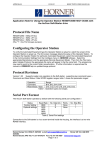
1. Install the CBREEZE software on your PC (if not already done). Double-click on CBREEZE Software
icon; and the default screen shown below appears.
Figure 2.1 - Default Screen
2. From Configure, pick Select Terminal Type and choose the model.
3. Connect the HE500TIU050/10X/11X/20X (PC Port) to a serial port (COM1, 2, 3 or 4) on the PC.
From the Configure menu, choose PC Comms Port and the applicable Comm port.
4. Connect power (+24VDC) to the HE500TIU050/10X/11X/20X. Power-up the unit. The type of
protocol currently installed is displayed in the lower half of the screen during power-up.
5. If the AE is different than the protocol currently installed on the HE500TIU050/100/110/20X, a new
protocol must be loaded.
CH. 2 GETTING STARTED
6 APR 2002
PAGE 15
MAN0023-10
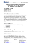
6. From the Configure menu, click Communication Settings and select manufacture of the AE,
followed by the type. The default setting for this equipment will be displayed in the window. Click OK
to accept.
Figure 2.2 – AE Configuration Box
7. If the default setting does not match the communications settings of the AE, select the appropriate
Baud Rate, Parity, Data Bits, Stop Bits and Communication Mode.
8. Network Mode enables the user to connect to one or many similar remote devices. Where a single
device is to be accessed disable network mode and enter the station address of the connected device
as the Global Remote Node ID.
Note: If connecting the TIU to a number of devices on the AE port (i.e. a multidrop system) then the
Network mode enable box should be ticked, and the node id required will need to be entered whenever
an automation equipment reference is required.
Note: If connecting the TIU to a single device on the AE port then the network mode enable box should
be unticked and the node ID for the single device entered as the global remote ID. All references to AE
equipment registers will now assume the global remote ID number entered here.
To update the protocol, select File, then Update TIU Protocol. The protocol file names take the general
form: - {plc_type}_r{release number}.{ser}
Where AE type is a prefix dependent on the protocol, release number is currently 4 and {ser} is 0xx for
Tiu050, 1xx for Tiu1xx and 2xx for Tiu2xx.
PAGE 16
MAN0023-10
6 APR 2002
CH. 2: GETTING STARTED
Note: Prior to release 4, protocol file names were of the form: - {plc_type}.{type} where type was LOS for
Tiu050 BOS for Tiu1xx and GOS for Tiu2xx. Dependant on the protocol and terminal type selected the
standard windows file open box will be displayed with the filename selected accordingly. Select the
protocol file you wish to download.
The appropriate protocol file for previously selected the automation equipment will be displayed in the file
name window. Select the folder name for the appropriate terminal type (0xx for Tiu050, 1xx for Tiu1xx
and 2xx for Tiu2xx). Click OK. A “SYSTEM SHUTDOWN”message appears on the
HE500TIU050/10X/11X/20X.
2.8
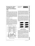
Proving Communications
Connect the HE500TIU050/10X/11X/20X to the automated equipment using the cable drawing provided.
Figure 2.3 – Start-up Menu
The following steps verify communications between the HE500TIU050/10X/11X/20X and the automation
equipment. The figures shown here are for the HE500TIU100. Methods are exactly the same for the all
products in the TIU range.
1.
Click on the Wizards Icon
look like figure 2.3.
in the tool bar and choose Comms Stats. The display should then
CH. 2 GETTING STARTED
6 APR 2002
PAGE 17
MAN0023-10
Note: The HE500TIU050/10X/11X/20X only communicates if an embedded data is put on the screen
2.
The settings can be saved. To do this, select Save Project As from File. Enter a file name and click
OK.
3.
Download the project to the HE500TIU050/10X/11X/20X. To do this, from the File menu select
Download Project to Tiu. A status bar appears indicating the progress of the download. On the
HE500TIU050/10X/11X/20X Display Screen, “SYSTEM SHUTDOWN”appears. A message of
“Transfer Complete”appears when the data has been successfully downloaded.
Note: If the error “Link Failed” appears, check the cable connection between the PC and
HE500TIU050/10X/11X/20X.
4.
After the transfer, the HE500TIU050/10X/11X/20X resets itself and the correct automation equipment
type is shown temporarily on the Display Screen.
5.
On the Display Screen, the “GOOD”number of communications should be equal to the “TOTAL”
number of communications. The content of the embedded data, on the top line, depends on the
existing data in that register of the PLC.
2.9
Icon Descriptions
The HE500TIU050/10X/11X/20X software main screen is shown in Figure 2.4. Along the top are several
short cut icons. Many are standard Windows icons, some however, are special function.
PAGE 18
MAN0023-10
6 APR 2002
CH. 2: GETTING STARTED
Figure 2.4 – HE500TIU050/100/110 Software Screen
2.10
Up/Down Keys
Left clicking on the “Up”and “Down”keys on the project window has the same effect as “Up”and
“Down”key presses (i.e., scroll up/down through the current menus). Right clicking on the “Up”and
“Down”keys on the project window have the same effect as Ctrl-Page Up and Ctrl-Page Down key
presses (i.e., enter sub menu, and leave sub-menu, respectively). If a sub-menu does not exist a
message appears saying “This page does not have a sub-menu, would you like to create one?”See
Creating a sub-menu later in this manual.
2.11
Key Symbols
The symbols for the four keys can be added to display pages using the PC function keys F2-F5. The
keys are assigned as follows:
1. F2 = PAUSE
2. F3 = UP
3. F4 = DOWN
4. F5 = ENTER
CH. 3: ABOUT PROJECTS
6 APR 2002
PAGE 19
MAN0023-10
CHAPTER 3: ABOUT PROJECTS
3.1
Scope
This chapter describes the procedure for configuring the HE500TIU050/10X/11X/20X. This includes
loading, saving, downloading, uploading, verifying and updating the protocol.
3.2
About TIU Terminal
This new feature allows the programmer to see what version level the connected terminal is at and how it
is configured. The information give is;
a. Operating System Version Level
b. Firmware Version Level
c. Protocol Version Level
d. Remote Equipment Manufacture
e. Remote Equipment Model
This can be used as a useful diagnostic tool when updating operating system and firmware. From the
main menu click Help/About TIU Terminal, a window similar to Figure 3.1 appears.
Figure 3.1 About TIU Terminal Configuration
3.3
Creating a New Project
1. Select New from the File menu.
2. The following prompt window appears:
Figure 3.2 – New Project
3. Click OK.
PAGE 20
MAN0023-10
6 APR 2002
CH. 3: ABOUT PROJECTS
3.4
Opening a Project
1. Press the “open folder”icon on the program display screen or select Open Project from the File
menu.
2. Select the proper file name from the list of available projects (with “cmc”extension).
3. Click OK.
3.5
Saving a Project
1. If the project has been previously saved during the current session, press the “floppy”disk icon on the
program display screen or select Save Project from the File menu
2. If this is the first time saving this project to a file, select Save Project As from the File menu.
3. Enter the file name and destination. Click OK.
3.6
Downloading a Project
Prior to the download the software checks if following conditions are correct: a) The correct TIU terminal is connected to the PC.
b) The correct Protocol file is loaded to the terminal.
c) The current revision operating system and firmware revision.
Note: If the message “Link Failed”appears, check the cables connecting the PC to the unit.
Note: If the message “This Terminal is fitted with the incorrect PLC protocol. Load the correct protocol
before loading the configuration into the terminal”. The project and the terminal are not set-up for the
same protocol. If the project is correct then download the correct protocol file to the TIU.
1. Select Download Project from the File menu. A status bar appears; indicating the download is in
progress.
2. After the project has been downloaded, the message “Transfer Complete”appears.
3. After the transfer, the HE500TIU050/10X/11X/20X resets itself.
4. The downloaded project now runs.
3.7
Uploading a Project
1. Select Upload Project from the File menu.
2. A status bar appears; indicating the upload is in progress.
Note: If the message “Link Failed”appears, check the cables connecting the PC to the unit.
3. After the project has been uploaded, the message “Transfer Complete”appears.
3.8
Verifying a Project
1. Select Verify Project from the File menu.
2. A status bar appears indicating verification progress.
3. The Verify will stop at all reported errors
CH. 3: ABOUT PROJECTS
6 APR 2002
PAGE 21
MAN0023-10
3.9
Updating the Protocol
When the software is installed the user decides where the main CBREEZE folder resides. During
installation the following folders are created: -
In the protocol directory 3 folders are created, TIU0xx, TIU1xx and TIU2xx. The protocol files for the
different terminal are loaded into these folders. The protocol files for the HE500TIU050 are loaded into
Tiu0xx, the protocol files for the HE500TIU10X are loaded into Tiu10x and the protocol files for the
HE500TIU20X are loaded into Tiu20x.
The name of the protocol file is broken up into three sections, the protocol, the main software revision and
the terminal type that protocol file is for.
Protocol Name
_
Software Revision
.
Terminal Type
Example
snp_R4.1xx
This is the protocol file for release 4 software for the GE FANUC PLC, for the HE500TIU10X
df1_R4.2xx
This is the protocol file for release 4 software for Allen Bradley PLC, for the HE500TIU20X
To Update Protocol File
1. Set Terminal Type
2. Set the required Automation Equipment in Communications Settings
3. Select Update TIU Protocol from the File menu.
4. Select the folder of the terminal you have connected to the PC. The correct file will appear for the
terminal type selected and the Automation Equipment selected. Select that file and click OK.
5. A status bar appears indicating download progress.
6. After the transfer, the HE500TIU050/10X/11X/20X resets itself. The correct PLC type is displayed on
the HE500TIU050/10X/11X/20X.
7. Next, the project loaded runs.
3.10
Updating the Operating System
1. There is a different operating system file for each terminal type. Therefore select terminal type first
and the software will request the correct file name for the current terminal type selected.
2. Select Update Operating System from the File menu.
3. Choose the updated file with the “BIN”extension. The operating system files are stored in the OS
folder under the CBREEZE folder. Only the correct file name will be displayed. Click OK.
4. A status bar appears indicating download progress.
5. During the download process, HE500TIU050/10X/11X/20X displays the message “SYSTEM
SHUTDOWN”.
PAGE 22
MAN0023-10
3.11
6 APR 2002
CH. 3: ABOUT PROJECTS
Printing
The HE500TSW232 software has printout capability. To print, select Print from the File menu or click on
the Print icon. The system parameters (# of menu pages, # of alarm pages, # of status pages, PLC type,
port settings, communication configuration, and PLC station number) and all of the pages are printed.
The printer set-up is selecting Printer Setup from the File menu. The printer set-up screen is shown in
Figure 3.3.
Figure 3.3 – Printer Set-up Box
3.12
To Insert a New Page
1. Click on the Insert Page Icon or from Edit choose Insert Page.
2. Pages can either be Insert After Current Page or Insert Before Current Page. Also, select the
number of pages to be inserted. Click OK.
Figure 3.4 – Insert Pages Message
3. If the user goes to the last page of the project and clicks on the down key the a messages appears
saying “There are no more pages in this menu, do you want to create some?”If the OK button is
pressed the above insert menu pages appears.
3.13
Default Page Type
(HE500TIU20X Only)
With the HE500TIU20X series there are two types of pages.
a. Text Page
b. Graphic Page
CH. 3: ABOUT PROJECTS
6 APR 2002
PAGE 23
MAN0023-10
The CBREEZE Software may be set-up to create either type of page by default or alternatively the
software can be set up to display a prompt asking which type page is to be created every time a page or
pages is inserted. (Prompt On Page Creation).
Text Page
A text page in the HE500TIU20X is similar to the normal page created with the HE500TIU10X/11X, i.e.
the same functions that are available on the HE500TIU10X/11X are also available on a Text Page of the
HE500TIU20X. To use the extra graphic features of the HE500TIU20X a Graphic page must be created.
Graphic Page
A graphic page can be used to display all the features of the Text Page plus the extra features available
for a Graphic Page. See chapter on Graphic Editor for further details of features available.
3.14
Download/Upload Character Set (Not available with the HE500TIU050)
After new characters have been created with the character generator, these characters must be
downloaded to the TIU. Conversely, an existing character set in the TIU can be uploaded.
3.14.1 To Download a Character Set:
1. Select Download Character Set to Tiu from the File menu. A status bar appears; indicating the
download is in progress.
Note: If the message “Link Failed”appears, check the cables connecting the PC to the unit.
2. After the project has been downloaded, the message “Transfer Complete”appears. The new
character set is now loaded to the TIU.
3.14.2 To Upload a Character set from the TIU:
1. Select Upload Character Set from the File menu.
2. A status bar appears; indicating the upload is in progress.
3. After the project has been uploaded, the message “Transfer Complete”appears.
3.15
Select Terminal Type
This software package supports the project of multiple Operator Stations (TIUs).
3.15.1 To select the Operator Station Terminal Type:
1. From Configure, pick Select Terminal Type and choose the model.
2. Choose the model or TIU being used. The screen changes to show the model just selected.
3.16
Delete a Page
1. Go to the page to be deleted. Click on the Delete Page icon or from Edit choose Delete Page.
2. The current page is deleted and the next page is displayed.
3.17
Font Size (Not available with the HE500TIU050)
There are four different Font Sizes: Normal, Double Height, Double Size (x2) and Four Times Size (x4).
The size of an entire line is set, individual words on a line cannot have a different size then other words.
3.17.1 To change/set the Font Size of a line:
1. Click somewhere on the line to be adjusted.
2. Click on the desired Font icon. The size of the entire line is adjusted. Any characters beyond the
right border of the screen are maintained but not displayed in the CBREEZE software or on the TIU.
3.18
Key Mapping
The keyboard can be mapped to PLC automation equipment along with the currently displayed page
number. This enables keys to be used in Jog/Instantaneous action modes. Sending the page number
allows the automation equipment to qualify the key states sent to ensure that the function only operates
PAGE 24
MAN0023-10
6 APR 2002
CH. 3: ABOUT PROJECTS
on the correct page. The page number is written to the specified data register, Page Mapping, and the
keys are mapped into the next contiguous data register, Key Mapping.
3.18.1 To enable key mapping:
1. From the Configure menu, select Keyboard Mapping.
2. Check the Enable box.
3. Choose the Register Type and the Map Page To Register. Click OK.
The Configure Key Mapping screen displays the data type, the active page number (from which the
keys are active) and the keyboard mapping bits.
Figure 3.5 - Configure Keyboard Mapping Box
3.19
Function Keys
The HE500TIU050/10X/11X/20X support function keys to be assigned in the project. The Up, Down,
Pause and Enter key can be configured as function keys however are defined on a per page basis. Due
to the fact that the keys may have other functions allocated to them the following restrictions are placed
on the allocation of functions to these keys:
1. The Pause key is available for mapping on status pages, alarm pages, and menu pages with no
editable embedded data, and which are not part of a submenu, and which do not have a submenu.
2. The Enter key is available for mapping on status pages, alarm pages and menu pages, except the
first menu page.
3. The Down Key is available for mapping on status pages and on the last page of a sub menu.
4. The Up Key is available for mapping on status pages and on the first page of a sub menu. (It is used
for scrolling purposes on menu pages that are not the first in a submenu, and on alarm pages.)
Along with the Up, Down, Pause and Enter keys, the alphanumeric keypad on the
HE500TIU050/11X/20X can also be assigned functions in the CBREEZE software. These function keys
can be programmed on all page types and menus.
CH. 3: ABOUT PROJECTS
6 APR 2002
PAGE 25
MAN0023-10
The Configure Function Key Screen lists the available function keys on each page. See Figure
3.6.
Figure 3.6 Configure Function Keys for the HE500TIU11X
Double Click on the key to be programmed. Each key maybe programmed as a Global or Local function
key. Programmed as a Local function, the key will only complete the function in the present page only.
Programmed as a Global function, the key will perform the function on every page of the project,
provided it is not overridden on a particular page with a local function.
Note: The Up, Down, Pause and Enter keys can only be programmed as Local Function Keys.
The Key Actions for both Local and Global are:
1. Disabled
2. Push Button
3. Preset Register
4. Display Page
5. Ramp Register
6. Set Bit
7. Clear Bit
8. Invert Bit
9. Execute Maths
PAGE 26
MAN0023-10
6 APR 2002
CH. 3: ABOUT PROJECTS
Figure 3.7 Function Key Definition
1. Disabled
Default setting, change to any other of the setting to enable function key.
2. Push Button
Sets the register chosen in the Location and Set Data type to the value in the Value field while the
button is pressed. The register is reset when the button is released.
3. Preset Register.
Sets the register chosen in the Location and Set Data type to the value in the Value field.
4. Display Page
Displays the specified page in the Page Number field.
5. Ramp Register
Increases the value of the Data Type or register type specified under the Location field by the value
entered in the Value field.
6. Set Bit
Sets the bit specified in the Bit field of the Location, of the Data Type or register type to “1”.
7. Clear Bit
Sets the bit specified in the Bit field of the Location, of the Data Type or register type to “0”.
8. Invert Bit
Toggles the bit specified in the Bit field of the Location, of the Data Type or register type.
9. Execute Maths
Executes mathematic function beginning at the specified line number.
CH. 3: ABOUT PROJECTS
6 APR 2002
PAGE 27
MAN0023-10
3.19.1 Function Key LEDs on HE500TIU20X
Function Key F9 – F18 have corresponding LEDs above or below the function key, indicating if the
function is programmed or not. These LEDs light up when the corresponding Function Key is
programmed to execute a function. When the function key is programmed as a Global Function Key then
the LED is lit up constant as the user goes through the programmed menu screens, on the terminal.
When the function key is programmed as a Local Function Key then the corresponding LED is only lit
when the page in which the local function is programmed is displayed on the terminal.
PAGE 28
MAN0023-10
6 APR 2002
NOTES
CH. 3: ABOUT PROJECTS
CH. 4: EMBEDDED DATA
6 APR 2002
PAGE 29
MAN0023-10
CHAPTER 4: EMBEDDED DATA
4.1
Scope
On the HE500TIU050/10X/11X up to 8 embedded data fields may be placed on each page. On the
HE500TIU20X up to 64 embedded data fields may be placed on each page. Embedded data types are
numeric (monitor or editable), alphanumeric (monitor only on the HE500TIU10X, editable on all other
models), timer (monitor or editable), bit status (monitor or editable), system variable (monitor only),
password (entry only in operation), Horizontal Fill, Text Selector, Recipe item, and Clock Calendar. Many
of the sections in this chapter contain specific instructions that are intended to serve as examples
only.
Note: If range checking is enabled, then increments and decrements are only allowed between the
maximum and minimum ranges.
There are 4 ways to embed data onto the screen.
a. Double click the Display window area.
b. Click the Embed Data icon
c. Chose Edit/Embedded data from the menu.
d. Press Shift and Enter Keys together.
If you double click the display window area or click the Embed Data icon the following screen appears
(Fig 4.1). From this the programmer can pick which type of data they wish to embed.
Alphanumeric Data Type
Timer Data Type
Bit status
Password
Numeric
Data Type
Clock Calendar
Trend
Recipe Item
Graph
Analog Meter
System
Variable
Text Selector
Figure 4.1 – Chose Embedded Data Type
Analog
Bit Map
Selector
PAGE 30
MAN0023-10
6 APR 2002
CH. 4: EMBEDDED DATA
4.2
Numeric Data
4.2.1 Scope
This section describes the Numeric Data functions available in the HE500TIU050/10X/11X/20X. Use the
instructions as follows to embed Numeric Data.
From the Embedded data list select Numeric Data, the screen shown in Figure 4.2 appears.
Figure 4.2 – Numeric Data Type Box
1.
Select a Data Type (register or other) and enter a number for the Location (100 for example).
Note: For numbers 0-65535, use 16 Bit Unsigned format. For numbers 0-999999999, use 32-Bit
Unsigned format. When 32-bit is selected two contiguous registers are read from the AE if the AE
register specified is a 16 bit register. The first register read contains the low word and the second register
contains the high word. The data source register specifies the first of two registers. Where the AE
register is a 32 bit register, for example on A MOOG PSC100, only a single register is read.
2.
3.
If 16 Bit and Signed is chosen from Format, then numbers -32768 TO 32767 may be utilised.
The signed, 32-Bit format for numbers -999999999 to 999999999 may be selected by clicking on
32-Bit and Signed.
CH. 4: EMBEDDED DATA
6 APR 2002
PAGE 31
MAN0023-10
4.2.2 To edit numeric data:
1. Check the Edit\Write box.
2. To enable range checking, check the Range Checking box and enter a Maximum and Minimum
range number (100 and 5 for example).
4.2.3 To change data registers contents from the HE500TIU050/10X/11X/20X:
1. Press the Pause key to select the data field for editing. The selected field becomes highlighted.
2. To increment the data, press the Up key.
3. To decrement the data, press the Down key.
4. On Terminals HE500TIU050/11X/20X the numeric pad may be used as an easier way to enter data.
5. To enter the data to the PLC, press the Enter key. If range checking is active, then increment and
decrement are only allowed between the maximum and minimum ranges.
4.3
Alphanumeric Data
4.3.1 Scope
This section describes the Alphanumeric Data functions available in the HE500TIU050/10X/11X/20X.
Use the instructions as follows to embed Alphanumeric Data.
From the Embedded data list select Alphanumeric Data, the screen shown in Figure 4.3 appears.
Figure 4.3 – Alphanumeric Data
PAGE 32
MAN0023-10
6 APR 2002
CH. 4: EMBEDDED DATA
4.3.2 To embed alphanumeric data:
1. Select Data Type. Enter a number for the Location (100 for example).
2. Enter the Number Of Characters to be displayed. One character is a byte (8 bits). To have 10
characters, five registers are read.
4.4
Timers
4.4.1 Scope
This section describes the Timer functions available in the HE500TIU050/10X/11X/20X. Use the
instructions as follows to embed Timers.
From the Embedded data list select Timers, the screen shown in Figure 4.4 appears.
Figure 4.4 – Timers
CH. 4: EMBEDDED DATA
6 APR 2002
PAGE 33
MAN0023-10
4.4.2 To monitor Timers on the HE500TIU050/10X/11X/20X.
1. Select a Data Type, and enter Location number.
2. Select a timer format under Format. Table 6.1 shows the available timer format. A 32-bit timer reads
two contiguous registers.
3. Check the Edit Enable box to allow for the editing of the time format.
4. Check the Range Checking box to enter a Maximum and Minimum range.
5. Range checking can be entered in SECONDS; MINUTES, SECONDS; or HOURS, MINUTES,
SECONDS.
4.4.3 To edit the data field:
1. While displaying the appropriate page, press the Pause key to select the data field for editing. The
selected field becomes highlighted.
2. To increment the data, press the Up key.
3. To decrement the data, press the Down key.
4. To enter the day to the PLC, press the Enter key. If range checking is active, then increment and
decrement are only allowed between the maximum and minimum ranges.
Table 4.1 – Configurations for Timer Format
16-Bit MM:SS
12 Hour
Minutes & Seconds
16-Bit HH:MM:SS
12 Hour
Hours, Minutes & Seconds
16-Bit MM:SS_T
12 Hour
Minutes, Seconds & 10th of Seconds
16-Bit HH:MM:SS_T
12 Hour
Hours, Minutes, Seconds & 10th of Seconds*
16-Bit HH:MM
12 Hour
Hours &Minutes.
32-Bit MM:SS
24 Hour
Minutes & Seconds
32-Bit HH:MM:SS
24 Hour
Hours, Minutes & Seconds
32-Bit MM:SS_T
24 Hour
Minutes, Seconds & 10th of Seconds
32 Bit HH:MM:SS_T
24 Hour
Hours, Minutes, Seconds & 10th of Seconds
32-Bit HH:MM
24 Hour
Hours &Minutes
* up to a maximum of 1:49:13.5
4.5
Bit Status
4.5.1 Scope
This section describes the bit status functions available in the HE500TIU050/10X/11X/20X. Use the
instructions as follows to embed Bit Status.
1.
2.
3.
4.
5.
6.
7.
8.
From the Embedded data list select Bit Status
Select the Data Type (%I for example). Select Token Pair (“OFF”/”ON” for example).
Enter a number for the Location (register or other, 10 for example).
If a word Data Type is chosen, enter a Bit Number in the range of 0-15 under Format. If bit 0 is off,
then “OFF”is displayed. If bit 0 is on, then “ON”is displayed.
To modify a token pair, select the token pair to be modified.
Click Edit Tokens.
Enter the “ON”and “OFF”descriptions (up to 10 characters) in the Enter Bit On Token and Enter Bit
Off Token boxes.
After being modified, the modified token pair can now be selected as normal.
PAGE 34
MAN0023-10
6 APR 2002
CH. 4: EMBEDDED DATA
Figure 4.5 – Configure Bit Status
4.5.2 To select the data field for editing:
1. From the appropriate page, press the Pause key. The selected field becomes highlighted.
2. To turn the bit off or on, press the Down key or the Up key and press “Enter”to send the data to the
PLC.
CH. 4: EMBEDDED DATA
6 APR 2002
PAGE 35
MAN0023-10
4.6
System Variables
4.6.1 Scope
This section describes the system variables available in the HE500TIU050/10X/11X/20X. Use the
instructions as follows to embed system variables.
There are six different types of system variables. To embed system variables:
1. From the embedded data list select System Variable.
2. Select a system variable type under Select System Variable in the Format section.
3. Click OK.
Figure 4.6 – Configure System Variable
4.7
Passwords
4.7.1 Scope
This section describes the Password function available in the HE500TIU050/10X/11X/20X. Use the
instructions as follows to embed Password.
4.7.2 To password protect a sub-menu:
1. From the embedded data list select Password. A series of question marks appear on the screen.
Click OK
2. Select Create SubMenu from the Edit menu. Enter the number of pages, you then have the option of
password protecting the submenu.
3. There are two types of security access on sub-menus.
• Simply one password to enter the sub-menu
• Authority Level Mode
Figure 4.7 – Configure Password
PAGE 36
MAN0023-10
6 APR 2002
CH. 4: EMBEDDED DATA
The Authority Level Mode allows the programmer to give security levels to each sub-menu. Click
Authority Level Mode and then enter the Authority Level to that sub-menu. Each Level can be given an
individual password.
Figure 4.8 – Configure Password Authority Mode
4.7.3 To enter the password from the HE500TIU050/10X/11X/20X:
1. In the appropriate page, press the Pause key. The selected field becomes highlighted.
2. Enter the password by incrementing or decrementing the data field, by pressing the Up or Down key
respectively.
3. Press the Enter and Up keys simultaneously.
4. The data must be equal to the pass code in order to enter into the sub-menu.
CH. 4: EMBEDDED DATA
6 APR 2002
PAGE 37
MAN0023-10
4.8
Analog Meters
4.8.1 Scope
This section describes the Analog Meters function available in the HE500TIU050/10X/11X/20X. Use the
instructions as follows to embed Analog Meters.
An area of the display can be horizontally filled to create an analogue meter or gauge. The height of the
block is fixed at the height of the current text line. To create a horizontal fill:
1. From the embedded data list select Analog Meters. Select the Data Type and Location under Data
Source.
2. Type the Number of Characters under Format. The maximum width of the block is determined by
the width of the page and the character size.
3. Select the Maximum and Minimum range. Minimum and maximum values define empty and full
scale, respectively.
Figure 4.9 – Configure Analog Meters
Note: Only 16-bit registers may be read from the PLC. Only linear scaling is supported.
PAGE 38
MAN0023-10
6 APR 2002
CH. 4: EMBEDDED DATA
4.9
Text Selector
4.9.1 Scope
This section describes the Text Selector function available in the HE500TIU050/10X/11X/20X. Use the
instructions as follows to embed Text Selector.
Text Tables are available in the HE500TIU050/10X/11X/20X CBREEZE software. There are 250
available text tables for use and they may be numbered from 1 to 250. Each text table may have up to
256 entries (numbered 0 to 255). Entries within each table may be called up by using the selected PLC
register. When the ID of the entry is called up in the PLC register, the text string (entry) is displayed. The
text strings are automatically forced to the width of the longest text string in the table (selected table).
Strings are automatically left justified. Text tables are typically used in situations where the operator
desires a visual message when some event (such as a value change in a register) occurs.
Example: A PLC is controlling a process that manufactures one of four drink types: Cola, Lemonade,
Orange Juice, and Apple Juice.
The PLC has a register that contains the value of “6”when Cola is being made, “8”when lemonade is
being made, “12”when Orange Juice is being made and “24”when Apple Juice is being made. A Text
table can be created with four entries, 6, 8, 12 and 24, with the text for these items being the four
products. Now, the PLC register can be monitored and the appropriate text inserted into a page on the
HE500TIU050/100/110.
A maximum of 64kBytes can be used by all of the text tables.
4.9.2 Edit Text Tables
Text tables can be edited from the HE500TIU050/100/110. To choose the Text Selector function:
1. Select Text Selector embedded data list.
2. Select a Data Type and choose a number for the Location. The value in the Location (register or
other) determines the text string (entry) number displayed (see 6.11).
Figure 4.10 – Configure Embedded Data Box
CH. 4: EMBEDDED DATA
6 APR 2002
PAGE 39
MAN0023-10
3.
Select a text Table ID number (1-250).
4. If you want the ability to edit the text string from the HE500TIU050/10X/11X/20X, click the Edit
Enable box.
5. To create/edit/delete entries, click the Edit Table button.
6. A Text Table box appears and the user has the ability to Add, Delete, and Edit text strings.
4.9.3 To Add an Table Entry
1. Click Add Figure 4.11 is displayed.
2. The field ID is automatically the next the available number in the table. This can be changed by typing
in the number required or incremented using the up and down buttons to the right of the field.
3. In the text field enter the text corresponding to that field ID.
4. The size of the font which the text will be displayed can then be set to the character set sizes 6 x 8 or
12 x 16.
5. The programmer can enter the customised character generator by clicking edit font, see Chapter on
Character Generator for further details.
Figure 4.11 – Text Table Field Entry
Text tables can be called in 3 different modes, Decimal, Binary and Hexadecimal. This refers to the
format of the data in the register calling the text table. Also in Binary mode multiple text table entries can
be displayed the user can then scroll between these text table entries, or set the Auto Scroll option to let
the TIU to automatically scroll between all the selected entries.
Figure 4.12 – Edit Text Table Entries
PAGE 40
MAN0023-10
6 APR 2002
CH. 4: EMBEDDED DATA
4.9.4 To edit a text table from the HE500TIU050/10X/11X/20X:
1. Select the text string field by pressing the Pause key.
2. Move up or down the list using the Up and Down keys.
3. Press the Enter key to select the desired text string.
4.9.5 To Export/Import a Text Table
a. Export
1.
Click the Export button.
2.
Enter the location of the file.
3.
Enter the name the file the text table is to be exported to.
b. Import
1.
Click the Import button.
2.
Click on the file to be imported.
4.9.6 Auto Mask Bit
The Auto Mask function allows the programmer is a function, which allows the programmer to mask off a
specified number of bits in a register. When the Auto Mask Bit is selected an extra field appears in the
Configure Text Selector Embedded Data window called Bit Offset. This field contains the number of bits
to be masked off beginning with the first bit of the register.
Figure 4.11 – Bit Off Set field
4.9.7 Default Text Table Entries
If an undefined value is entered into the text table entry field (i.e., a value that has not been assigned in
any text table), then one of two different things happen.
a. If the user has assigned a value to the Default Entry in the Text Table box, then that entry number is
displayed. This value is assigned by first checking the box next to Default Entry, then entering a
number in the box below.
CH. 4: EMBEDDED DATA
6 APR 2002
PAGE 41
MAN0023-10
b. If the box is unchecked and a default entry has not been selected, then a series of asterisks
(corresponding to the longest entry in the text table) are displayed.
Example: There are four entries in the text table. These four entries have numbers of 23, 24, 54 and 67.
The text in these entries is as follows:
23 - Cola
24 - Soda Water
54 - Apple Juice
67 - Orange Juice
100 Undefined
If an undefined value is entered (e.g. 97) then “************”is shown. If a default entry has been selected,
i.e., 100 (any number can be used), then the text corresponding to 100, “Undefined”is displayed.
Figure 4.12 – Text Table 1
4.10
Clock Calendar
4.10.1 Scope
This section describes the Clock Calendar function available in the HE500TIU050/10X/11X/20X. Use the
instructions as follows to embed Clock Calendar.
If the HE500TIU050/100/110 has been fitted with the real-time clock feature, then the time and/or date
can be embedded as data. To embed the time and/or date:
1. Select Clock Calendar under embedded data list.
PAGE 42
MAN0023-10
6 APR 2002
CH. 4: EMBEDDED DATA
Figure 4.13 – Configure Clock Calendar Data
2. Choose the Format of the time and/or date to be displayed on the HE500TIU050/10X/11X/20X. Click
OK.
4.10.2 Clock Calendar Mapping
It is also possible to map the clock calendar (time and date) information to the automation equipment. To
do this:
1. From Configure, chose Clock Calendar Mapping.
2. Click Enable. Select the Data Type (register or other) and first register (or other) for the Map Start.
Click OK.
3. The mapping is displayed in the Map field (see Figure 4.14).
Figure 4.14 – Clock Calendar Mapping
CH. 4: EMBEDDED DATA
6 APR 2002
PAGE 43
MAN0023-10
4.11
Menu Timeout
4.11.1 Scope
This section describes the Menu Timeout function available in the HE500TIU050/10X/11X/20X. Use the
instructions as follows to embed Menu Timeout.
The Menu Timeout is a useful safety feature. This forces the HE500TIU050/100/110 back to the first
(main) menu page after a set time period. For example, the HE500TIU050/100/110 is on an input menu
page, after 30 seconds of no activity, the HE500TIU050/100/110 reverts back to the non-input (safety)
main menu page. To set the timeout:
Figure 4.15 – Set Menu Timeout Box
From the configuration menu, select Configure, then Menu Timeout. A timeout is set in ALL menu and
sub-menu pages. Time-outs in each screen may be inhibited from the Edit menu. To disable the Timeout
function, set the time to 0 seconds.
PAGE 44
MAN0023-10
6 APR 2002
CH. 4: EMBEDDED DATA
4.12
Flashing Characters
4.12.1 Scope
This section describes the Flashing Characters function available in the HE500TIU050/10X/11X/20X.
Use the instructions as follows to embed Flashing Characters.
The user may have flashing characters on any line and on any type of page in the project. There are two
different ways that flashing characters are implemented.
a. In the embedded data screen, under Attributes check the box for Flashing.
b. The other way to create flashing characters is to use the “TAB”key when you are creating the project.
Flashing is toggled by line using the “TAB”key (current line the cursor is on). In this case, the entire
line flashes.
Note: Flashing can not be enabled or disabled conditionally.
4.13
Set the Real-time Clock
4.13.1 Scope
This section describes the Set the Real-time Clock function available in the HE500TIU050/10X/11X/20X.
Use the instructions as follows to embed Set the Real-time Clock.
The Real-time Clock is not a standard feature on all TIUs. The Real-time Clock is set from the PC’s clock.
To automatically set the Real-time Clock from the PC’s clock:
Connect the TIU to the PC.
From File, choose Set Clock. The PC's time is downloaded to the Unit
4.14
Scaling
4.14.1 Scope
This section describes the Scaling function available in the HE500TIU050/10X/11X/20X. Use the
instructions as follows to embed Scaling.
Embedded Fields can be Scaled to convert register values from the AE into real-world numbers.
4.14.2 To enable Scaling:
1. From the Embedded Data screen, click Enable in the Scaling box.
2. Enter the TIU Minimum, TIU Maximum, Remote Minimum and Remote Maximum.
3. After configuring any other fields, click OK.
The TIU Minimum and Maximum refer to the minimum and maximum values to be displayed on the TIU.
The Remote Minimum and Maximum refer to the minimum and maximum values produced by the AE.
Example. Scaling can be used to convert the drive speed in RPM to a conveyor's speed in m/min. This
scaling could then be taking the gearbox and all the other mechanical factors into account. The
maximum speed of the drive may be 1450, but the actual maximum speed of the conveyor is 100 m/min.
Therefore, the Scaling configuration is as follows:
TIU Minimum
0 (m/min)
TIU Maximum
100 (m/min)
Remote Minimum
0 (RPM)
Remote Maximum
1450 (RPM)
CH. 4: EMBEDDED DATA
6 APR 2002
PAGE 45
MAN0023-10
4.15
Page Wizard
4.15.1 Scope
This section describes the Page Wizard function available in the HE500TIU050/10X/11X/20X. Use the
instructions as follows to embed Page Wizard.
The Page Wizard is a short cut for building pages to set or view the internal real-time clock or view
communication statistics.
Figure 4.16 – Page Wizard
4.15.2 To use the Page Wizard:
1. Move to or insert a page that is to be built.
2. Click the Page Wizard icon or from Configure, choose Page Wizard.
3. Click on the Page Type to be built and chose the particular Parameters to be displayed on the TIU.
Click Build Page.
4.16
Graphing (Not available with the HE500TIU050)
4.16.1 Scope
This section describes the Graphing function available in the HE500TIU050/10X/11X/20X. Use the
instructions as follows to embed Graphing.
This features graphs up to two plots of 21 contiguous registers. Plot 1 is the lower byte of the register
and plot 2 is the upper byte of the register. The graph is updated continuously. The actual update time
depends on the equipment connected to the TIU, and communication speed. The data structure is as
follows:
PAGE 46
MAN0023-10
Offset +0
Points
6 APR 2002
Offset +1
Data 1
Offset +2
Data 2
. . .
. . .
CH. 4: EMBEDDED DATA
Offset +21
Data 21
Points HIGH Byte = Number of point for plot 2
LOW Byte = Number of points for plot 1
Definitions:
0 = do not plot;
1 = plot first 11 registers on X-axis using 10 pixels per register;
2 = plot 21 registers on X-axis using 5 pixels per register;
>2 = assume 2.
Data
HIGH Byte = Data for plot 2, ploted with a dotted line
LOW Byte = Data for plot 1, plotted with a solid line
The scale of the Y-axis is 0 to 29. Values greater than 29 or negative values are plotted full
scale.
4.16.2 To Embed a Graph:
Figure 4.17 Embedding A Graph
1.
2.
3.
4.
Select Embedded Data from the Edit menu
Select Graph under Type.
Select a Data Type (register or other) and a Location (this is the First Data register, ).
Enter the number of points on the Graph, the number of points equals the number of data registers
required.
CH. 4: EMBEDDED DATA
6 APR 2002
PAGE 47
MAN0023-10
5. Click OK.
4.16.3 Enable Axes
When this option is selected the X and Y-axes of the Graph is displayed on the
HE500TIU11X/HE500TIU20X when the project is downloaded.
Note: The graph uses up 3/4 of a menu or submenu page and as such overwrites whatever data is on
that page.
4.17
Trending (Not available with the HE500TIU050)
4.17.1 Scope
This section describes the Trending function available in the HE500TIU050/10X/11X/20X. Use the
instructions as follows to embed Trending.
This features continuously plots up to two registers (channels) versus time. The maximum update rate
depends on the equipment connected to the TIU, and communication speed.
Figure 4.18 Embedding A Trend
4.17.2 Enable Axes
When this option is selected the X and Y-axes of the Trend are when the project is downloaded.
PAGE 48
MAN0023-10
6 APR 2002
CH. 4: EMBEDDED DATA
4.17.3 Data Indirectly Specified.
This option allows the programmer to indirectly specify the register which contains the data for the trend,
i.e. the contents of the register, which is specified in the Location section of the Remote Data Source,
specifies the register that contains the data for the trend.
4.17.4 Control Data from Remote Device
This option allows the programmer to control the set-up of the trend from registers stored in the
automation equipment. The structure for setting up the trend is described further in this paragraph.
The data structure is as follows:
Offset +0
Time Base
Time Base
Offset +1
Ch. 1 Scale
Offset +2
Ch. 1 Data
Offset +3
Ch. 2 Scale
Offset +4
Ch. 2 Data
Offset +5
Width
0 = maximum update rate;
1 = 1/10s per plot
X = X/10s per plot, up to X=10
Scale Maximum value of Y-axis for that channel; if 0 channel is not plotted.
Data
Raw register values. Negative values are plotted at full scale.
Width Number of samples across the display
100 = 1 pixel per plot
50 = 2 pixels per plot
25 = 4 pixels per plot
10 = 10 pixels per plot
Any other value, the nearest to the above 4 is used.
If the Control Data from Remote Device option is not clicked then the trend is set-up as follows.
The Time Base is set by the Trend Width.
The scale is set by the Minimum and Maximum Range
The data for the first trace is taken from the register specified or indirectly specified in the Location field
The data for the second trace is taken from the following register specified or indirectly specified in the
Location field.
Note: When Control Data from Remote Device is selected, the data to set-up the structure of the trend is
only read once, when you first go onto a screen where the trend is embedded. The data for the trend is
read continuously.
4.17.5 To Embed a Trend
1. Select Embedded Data from the Edit menu
2. Select Trend under Type.
3. Select a Data Type (register or other) and a Location.
4. To display axes with the graph, click the Enable Axes under Format.
5. Click OK.
Note: The trend uses up 3/4 of a menu or submenu page and as such overwrites whatever data is on that
page.
CH. 5 CHARACTER GENERATOR
6 APR 2002
PAGE 49
MAN0023-10
CHAPTER 5: CHARACTER GENERATOR
5.1
Scope (Not available on the HE500TIU050)
The CBREEZE software allows the user to edit, create and display on the HE500TIU10X/11X/20X special
characters. These characters may be company logos, special symbols or multilingual, non-standard
KEYBOARD characters such as Ω, é, °, © or ±.
Note: The character set for the font double height is scaled automatically from the 8x6-character set. The
character set for the font x4 is scaled automatically from the 16x12-character set.
Within each character set are up to 256 characters, however, not all these characters are usable and/or
editable by the user.
Characters 0 to 31
Characters 32 to 127
Characters 128 to 160
Characters 161 to 255
5.2
1.
2.
Table 5.1 – Make-up of a Character Set
System characters – not useable or editable
Standard keyboard characters – useable and editable although it
is not recommended the user edit these characters.
Editable and useable characters. This is the area of the
character set for use.
Extended keyboard characters – useable and editable although it
is not recommended the user edit these characters.
To Insert a Special Character:
Place the pointer on the display where the character is to go.
Press <Ctrl> <Enter> or by clicking right mouse button. Click on the character in the Character
Map (see Figure 5.2) to be inserted.
PAGE 50
MAN0023-10
5.3
1.
6 APR 2002
CH. 5: CHARACTER GEN.
To Create Or Edit a Character:
From Configure on the menu bar, choose Fonts. The screen in Figure 5.1 appears.
Character Size
Character Number
Name of Set
Edit Standard
keyboard Characters
Saves Character File
Loads Character File
Doubles the size of
the 8x6 set only
Click on a square to toggle that square on or
off or drag and draw white of black lines.
Shows spacing
Figure 5.1 - Character Generator Screen
2.
Under Character Set, choose the Character Size to be edited. Beside Set Name, enter a name
that describes this set.
3.
Click on Map to show the total character set. The screen in Figure 5.2 appears. The first four
rows are the standard keyboard characters, which should not be edited. The fifth row is editable
and useable. The lower three rows are the extended keyboard characters, which should not be
edited. Click on the character to be edited or blank box to create a character.
Edit this row
Figure 5.2 – Character Map
NOTE: Standard and Extended keyboard character are editable; however, this must be done with caution
as it effects how characters are displayed on the HE500TIU050/100/110, i.e., changing “4”to •causes all
4’s from the PLC to be displayed as •
. 454 is displayed as •
5•
.
4.
Under the Character Bitmap (see Figure 5.1), click on a square (pixel) to toggle that square on
or off. The grey area is the space between characters and these squares should not be turned on.
5.
Go to step 3 to edit the next character.
CH. 5 CHARACTER GENERATOR
6.
6 APR 2002
PAGE 51
MAN0023-10
Once all the characters have been created or edited, click Save File. Choosing Yes over-writes
the current character file. Choosing No gives the option to save this character set under a new
file name.
Note: It is possible to double the size of an 8x6-character set. To do this click on the Double button. It is
not possible to half the size of a 12x16-character set. It is recommended that the 8x6-character set be
created first and then doubled.
5.4
International Keyboards
The CBREEZE software supports various international keyboard layouts. However, if the standard or
extended keyboard characters are edited or deleted, the pressed key may appear different or not at all.
The following keyboard layouts are supported:
Table 5.2 – Supported Keyboard Layouts
Danish
German (Standard)
Dutch (Belgium)
Italian (Standard)
Dutch (Standard)
Norwegian
English (All)
Spanish (Modern Sort)
Finnish
Swedish
French (Standard)
PAGE 52
MAN0023-10
6 APR 2002
NOTES
CH. 5: CHARACTER GEN.
CH. 6: RECIPES
6 APR 2002
PAGE 53
MAN0023-10
CHAPTER 6: RECIPES
6.1
Scope
Recipes allow the user to send or update multiple registers simultaneously. For example, it may be
desired to run a motor at two different settings for two different applications.
a. Speed of 1000RPM, minimum frequency of 500Hz, acceleration rate of 1000 s/100Hz and
deceleration rate of 2000 s/100Hz;
b. Speed of 500RPM minimum frequency of 400Hz, acceleration rate of 500-s/100Hz and
deceleration rate of 1500 s/100Hz.
Recipes enable the user to download all the fields (four in this example) at the same time without editing
each individual field.
A maximum of 63 fields and 1024 records are supported by the database. The total storage available to
the database is 64 kBytes. The number of bytes currently in use can be obtained from the main
CBREEZE help menu under About CBREEZE.
6.2
To Enable Recipes:
1. From Configure, select Recipes. Enter the Recipe Name, Number of Records in the Database
and Number of Fields in Record. The number of Records and Fields can be changed later. Click
OK.
Fig 6.1 Database Editor Window
2. The TIU Recipe Database Editor appears. Set the number of Records (different settings) and Fields
(parameters).
3. Edit the Fields and Records as desired.
4. From File, select Exit to leave the Recipe Editor.
6.3
To Edit Recipe Fields and Records:
1. Open the Recipe Editor by clicking on the Recipe icon
on the Toolbar or from
Configure/Recipes.
2. Left click on the Field to be edited. Enter the Ingredient Name, Type Remote Data Source
(register) and Format in the same manner as Embedded Data. Enable Scaling if desired.
3. Left click on the Record to be edited. Enter the value and click OK or press <Enter>.
4. From File, select Exit to leave the Recipe Editor.
PAGE 54
MAN0023-10
6 APR 2002
CH. 6: RECIPES
6.4
Editing Ingredient Properties
An ingredient, or field, in the database corresponds to a value which will be loaded to a specified location
either internal to the TIU or in the connected automation equipment.
Figure 6.2: - Ingredient Properties
Each field has the following properties: a) Ingredient name
An alphanumeric string that is used to specify which field in a recipe is being edited. The string may be up
to 30 characters in length.
b) Type
Currently recipe data fields may be formatted as numeric, timer, alphanumeric or bit.
c) Remote data source
The register to which the recipe field data will be transferred when the recipe is selected for loading.
Where the type is specified as alphanumeric it refers to the first register of a contiguous block where the
number of characters in the alphanumeric string defines the block size. (block length = (2 x (characters +
Refer to the alphanumeric embedded data section for more details on how an alphanumeric string is
stored.
d) Format
Additional data to specify the format of the data field dependant on its type.
CH. 6: RECIPES
6 APR 2002
PAGE 55
MAN0023-10
e) Range checking
Optionally set limits on numeric and timer data, which are applied when the operator modifies the data
from the keypad.
f) Scaling
Where the data is formatted as numeric or timer data, and the data is mapped to the automation
equipment, scaling allows an offset and multiple data transformation to occur prior to sending.
6.5
To Edit Recipe Data
Double click on the field to be edited. If the data is a bit status it will toggle, otherwise the following prompt
will appear: -
Figure 6.3: - Edit Data
Enter the data required for the field
6.6
To Rename a Record
1. Double click on the record name
Figure 6.4 – Record Name
2. Type in the new record name
3. Click OK.
PAGE 56
MAN0023-10
6 APR 2002
CH. 6: RECIPES
6.7
To Embed a Recipe on a Menu Page
When embedding a recipe item on a menu page the following box is displayed.
Figure 6.5 - Embed Recipe Item
The three format types are; a)
Recipe Selector
The Recipe Selector field allows the user to select a recipe from the database.
The recipe selector requires a field to be selected from the database, typically this will simply be the
record name.
The recipe selector initially displays the contents of the specified field within the first record in the
database. The operator will be able to scroll through the records in the database to select the record on
which he wants to operate. When the required record is found, the Enter key is pressed and the desired
record is selected.
The recipe selector is used either on it’s own, in which case the page is a recipe selection page and upon
selecting the record the contents of that record are transferred to the TIU internal registers and/or the
automation equipment. Otherwise the recipe selector is used in conjunction with a recipe field tag and a
recipe field contents embedded data field, in which case the page is a recipe editing page used to modify
the values loaded by the specified record when selected.
• Recipe Name will allow the user to edit the contents of each Item of the displayed Record; the
Record name will be displayed.
• If one of the Items is selected then the user can edit the contents of each Item of the displayed
Record; the Record number will be displayed.
b)
Recipe Field Tag
If the Recipe Field Tag is embedded on the menu page then the Item Name of the record selected for that
menu page will be displayed. The recipe field embedded data must always be used in conjunction with
both a recipe selector and recipe field contents embedded field. If all three recipe embedded data types
are on screen the page is used for editing a recipe. Initially when a page is displayed the recipe field tag
will be blank. It remains blank until a recipe has been selected using a recipe selector field. At this point
the first recipe field is selected for editing and the name of this field is displayed as the recipe field tag. As
the operator enters each recipe item, the recipe field tag moves on to the next field tag until all fields in
the recipe have been modified or accepted.
CH. 6: RECIPES
6 APR 2002
PAGE 57
MAN0023-10
c) Recipe Field Contents
If the Recipe Field Contents is embedded on the menu page then the contents of the current Item, of the
record selected for that menu page, will be displayed. The recipe field contents embedded data must
always be used in conjunction with both a recipe selector and recipe field tag embedded field. If all three
recipe embedded data types are on screen the page is used for editing a recipe. Initially when a page is
displayed the recipe field tag will be blank. It remains blank until a recipe has been selected using a
recipe selector field. At this point the first recipe field is selected for editing and the name of this field is
displayed as the recipe field contents. Once all the fields in the record have been accepted the modified
record is written to flash memory in the terminal. Note that to send the contents of the newly modified
record to the automation equipment and/or the TIU internal registers the operator must call up a recipe
selection page and select it in the normal manner.
Pressing the pause key at any point during the editing sequence will abort data editing, and cause any
changes to the recipe data already made to be ignored. The flash memory is only updated if all fields are
accepted with the Enter Key.
Because of the precise nature of the combinations in which the recipe embedded fields must be used in
order to achieve a specified function it is recommended that the page wizard is always used to build
recipe operation pages!
Note: A recipe item can be manually embedded on a menu page however for best results when
embedding a recipe item on a screen see the Page Menu Wizard for Recipe Items. This can always be
edited afterwards.
6.8
Importing and Exporting Data from a Recipe:
Recipe tables can be imported or exported. Files can be imported or exported as coma delimited (*.csv)
or as print files (*.prn). Other file types may be viewed but may not load properly.
Note: Only Records are exported and imported, the Field names are not.
Note: If the table size that the data has been imported into is smaller then the table it was imported from,
then not all of the data is displayed.
Note: Only one Record column can be selected per project at any time.
PAGE 58
MAN0023-10
6 APR 2002
NOTES
CH. 6: RECIPES
CH.7: TUTORIAL
6 APR 2002
PAGE 59
MAN0023-10
CHAPTER 7: TUTORIAL
7.1
Scope
This chapter contains instructions for using several of the HE500TIU050/100/110 features. The projects
in this chapter serve as examples and are not to be taken literally for all applications. After following this
tutorial, the user should have a better understanding of how the HE500TIU050/100/110 operates.
7.2
Menus
The HE500TIU050/100/110 supports a total of 300 pages divided between menu and sub-menu, alarm
and status pages. The following points are covered in this section:
1.
2.
3.
4.
5.
Menus can have sub-menus.
Sub-menus can have sub-menus.
There may be up to 8 embedded data per page.
Embedded data can be displayed-type or entry/editing-type.
Sub-menus can be password protected.
Additional menu pages may be created by selecting Insert Page from the Edit menu or by selecting the
“+”icon from the icon menu to the right of the Display screen. Selecting Delete Page from the Edit menu
or by selecting the “-“icon will delete the displayed page.
The next menu page may be selected by clicking the “Down”key or by selecting the Next Page from the
Goto menu. The previous menu page may be selected by clicking the “Up”key or by selecting Previous
Page from the Goto menu.
Example: The HE500TIU050/100/110 is used to monitor the temperature of a furnace and indicate the
heater or a fan is ON or OFF. This example uses a Hitachi H-252 series PLC, but is applicable to any
PLC with modifications.
PAGE 60
MAN0023-10
6 APR 2002
CH. 7: TUTORIAL
Figure 7.1 – Menu Page 1
1.
2.
3.
Communication Settings from Configure. Select the applicable automation equipment being
used, in this example a Hitachi H-series is used. Click OK. Update the Protocol if required
Menu Page 1 shows some explanatory details about the program and should look like figure 7.1.
For “Furnace Control #1”on line 3, click on the font double height icon at the beginning of the
line.
Click on the Insert Page Icon. Choose Insert After Current Page. Click OK.
CH.7: TUTORIAL
6 APR 2002
Figure 7.2 – Menu Page 2
Figure 7.3 – Menu Page 2
PAGE 61
MAN0023-10
PAGE 62
MAN0023-10
1.
2.
3.
4.
5.
6.
6 APR 2002
CH. 7: TUTORIAL
Enter the text as shown in Figure 7.2.
Place the cursor one space to the right of “Temperature”and embed a Numeric Data in WRREGISTERS Location 10. Select “XXX”, 16-Bit, Unsigned. Click OK. Correct “C”position.
On the first space of the fourth line, click the embed icon. Choose Analog Meter, WRREGISTERS and Location 3. Under Format, enter 15 for characters, 760 for Maximum and 0
for Minimum. Click OK.
Place the cursor 6 space to the right of “Heater”and embed a Bit Status in Y-REGISTERS,
Location 100, Select Token Pair Format, “OFF”/”ON.” Click OK.
Place the cursor 9 spaces to the right of “Fan”and embed a Bit Status in WR-REGISTERS,
Register 10, Select Token Pair Format, “OFF”/”ONFF”, Bit Number 1. Click OK.
After embedding the data, the screen looks like Figure 7.3.
Under the File menu, click Download Project.
The temperature is displayed digitally and as a bar graph by the horizontal fill. Also, it is shown whether
the heater and fan are ON or OFF.
Note: For this example to work a thermocouple and relay module must be used to simulate temperature,
heater and fan. Otherwise the latent values displayed will be blank or the values in the PLC registers.
7.3
Sub-Menus
Sub-menu pages branch off menu pages analogous to a sub-directory branching off a main directory of a
PC. The HE500TIU050/100/110 supports a total of 300 pages divided between menu and sub-menu,
alarm and status pages.
Example: Continuing from the example in Figure 7.2, one sub-menu is set up for the heater and one for
the fan. Each sub-menu sets the temperature (within the furnace) at which the heater or fan turns
ON/OFF.
Note: Ladder code needs to be written if this example is to work as anything more than an example.
1.
zz
2.
Go to menu page 2. Under the Create SubMenu page, choose 2 for the Number of Pages. Be
sure that the Password Protect box is unchecked. Click OK. The bottom middle cell should
display Menu Page 2.1 (indicating a sub-menu).
After completing this, enter the text as shown on the first sub-menu page (as follows):
CH.7: TUTORIAL
6 APR 2002
PAGE 63
MAN0023-10
Figure 7.4 – Sub-Menu Page 2.1
3.
4.
5.
Embed data one space to the right of “ON Temperature”by selecting Numeric for the Type, WRREGISTERS for the Data Type and Location 10. Under Format, select “XXX”, 16-Bit
Unsigned and click on Edit Enable. Click OK.
Do the same as in step 3 for “OFF Temperature”but use Location 11.
On the sixth line, one space to the right of “Manual Override”embed a Bit Status in WRREGISTERS, Register 10, Select Token Pair Format, “OFF”/”ON”, Bit Number 1, Click on Edit
Enable. Click OK.
PAGE 64
MAN0023-10
6 APR 2002
CH. 7: TUTORIAL
Figure 7.5 - Sub-Menu Page 2.1
6.
7.
Highlight the display screen, and select Copy from the Edit menu. Select Next Page from the
Goto menu. Select Paste from the Edit Menu. Change the “Heater”to “Fan”and Fan ON and
OFF temperature registers to 20 and 21, respectively. Change the Bit Number to 1 for the
embedded data beside Manual Override.
Return to the parent menu by selecting Parent Menu from the Goto menu.
Under the File menu, you can Save Project, then Download Project.
The Screen appears as in Figure 7.5.
7.3.1
1.
2.
3.
To Enter A Sub-Menu On the HE500TIU050/10X/11X/20X:
To go into a sub-menu from the main menu, press the Pause key and the Down key at the same
time.
To edit the data, press the Pause key. Press the Down key to decrement the data, the Up key to
increment the data and the Enter key to enter the data.
Press the Pause key and the Up key to return to the parent menu or the Down key to go to the
next sub-menu page.
CH.7: TUTORIAL
6 APR 2002
PAGE 65
MAN0023-10
7.4
Password-Protected Sub-Menus
7.4.1 Scope
This tutorial section of the manual covers how to create password-protected sub-menus.
Example: Continuing from the example in 7.2, one sub-menu is set up for the heater and another for the
fan. Each sub-menu sets the temperature (within the furnace) at which the heater or fan turns ON/OFF.
This is the same as the example in 7.3 except that the sub-menus are now password protected.
1.
2.
Create a new menu page by selecting Insert Page from the Edit menu.
Enter the text, as shown in Figure 7.6.
Figure 7.6 - Password Enter Screen
3.
4.
5.
6.
Place the cursor one space to the right of “CODE”and select Embedded Data from the Edit
menu. Select Password for the Type. Click OK. Four question marks should appear beside the
word “CODE”.
Go to menu page 3. Select the Modify SubMenu Properties, and choose 2 for the Number of
Pages Check the Password Protect box, and enter a Password of “1234”. Click OK. The
bottom middle cell should display Menu Page 3.1 (indicating a sub-menu).
Follow steps 2 through 8 in 9.3.
Save and Download Project to the HE500TIU050/100/110.
PAGE 66
MAN0023-10
6 APR 2002
CH. 7: TUTORIAL
The resulting display screen on the HE500TIU050/100/110 appears as the screen shown in Figure 7.7
(with a code of 0000).
Figure 7.7 - Password Enter Screen
7.4.2
1.
2.
3.
7.4.3
1.
2.
3.
4.
To Enter the Sub-Menu:
Press the Pause key to edit the Pass Code.
Press the Up key to increment the code, 1234 in this example (hold the key down for speed
incrementing), the Down key to decrement the data and the Enter key to enter the data.
Press the Pause key and the Down key at the same time to select the sub-menu page. The submenu page is only selected if the Pass Code is correct.
To Edit The data On The Sub-Menu Pages:
Press the Pause key to select the field to edit.
Press the Up key to toggle or increment the field. Press the Down key to toddle or decrement
the field. Press the Enter key to send the value to the PLC.
Press the Pause key to select the next field to edit.
Press the Pause key and the Up key at the same time to return to the parent menu.
CH.7: TUTORIAL
6 APR 2002
PAGE 67
MAN0023-10
7.5
Status
7.5.1 Scope
The HE500TIU050/10X/11X/20X can display STATUS information. For example, a status page can be
displayed as COILS change (in real-time) in your PLC, i.e., the first Coil displays the first Status page, the
second coil the second page and so on.
Status messages can have up to eight embedded data values per page. Up to 300 total pages are
available split between Status, Alarms and Menu pages.
Two different modes are available for configuring status pages. These modes are the Bit Mode and the
Direct Mode.
• Direct Mode reads only one register as a word from the PLC for the status page. If the value in
this register is zero or greater than the number of configured status pages in the system, the
main menu screen is displayed. Otherwise, the appropriate status screen is called up.
• Bit Mode works essentially the same, except that the screens are controlled by discrete bits
instead of the full word register values.
NOTE: Status pages are only displayed when MENU PAGE 1 is selected.
Example: The following example involves the HE500TIU050/10X/11X/20X connected to a GE Fanuc 9030 PLC. It is applicable to any of the supported automation equipment (see 7.3) with substitutions made
for the specific registering nomenclature, i.e., %Q is a discrete bit output. It is assumed the PLC is
properly configured, the HE500TIU050/10X/11X/20X is properly connected to the PLC, both are powered
up, and the CBREEZE software, HE500TSW232, is running on the PC.
1.
2.
3.
4.
Select Communication Settings from the Configure menu. Select the automation equipment
type you are using. For the example here, a “GE Series 90 SNP protocol”is being used. Click
OK.
Insert a menu page after Menu Page 1 (refer to 7.2 for instructions). Place the cursor at the left
on the first line. Click the double height icon. Type “Discrete Outputs:”
On the third line, type “Q1:”. Click on the Embed Icon. Select Bit Status from Type; discrete
output (in this example %Q) from Data Type; Location 1; leave Token Pair as “OFF”/”ON” and
click Edit Enable. Click OK. See Figure 7.8.
Do the same for Q2, Q3 and Q4 on lines 4, 5 and 6, incrementing the Bit Number by one. These
discrete outputs will simulate coils. Menu Page 2(2) should be the same as Figure 7.9.
PAGE 68
MAN0023-10
6 APR 2002
Figure 7.8 – Configure Embedded Data Box
Figure 7.9 – Menu Page 2(2)
CH. 7: TUTORIAL
CH.7: TUTORIAL
6 APR 2002
PAGE 69
MAN0023-10
From Configure, choose Status. Click Direct Mode. From Data Type choose discrete output (%Q in
this example); Block Start equals1. The Number of Status Pages equals 4. Click OK.
Figure 7.10 – Configure Status Pages
From View, choose Status. This displays the first of four status pages. On the third line, delete what is
there and type “Status Page:”on the fourth line, click on the x4 icon and type “1”in the centre of the line.
Status Page 1 appears as the screen in Figure 7.11. Highlight display screen,
click Edit and Copy.
Figure 7.11 – Configure Status Pages
PAGE 70
MAN0023-10
6 APR 2002
CH. 7: TUTORIAL
Click the down arrow icon on the project software to get to Status Page 2 of 4. Delete what is on the
display screen, then from Edit, choose Paste Page. Change the “1”on line four to a “2.” Do the same
for pages 3 and 4.
From File, choose Download Project
On the HE500TIU050/10X/11X/20X, press the DOWN key to get to the Discrete Output page (as in
Figure 7.8). Press the PAUSE key the toggle Q0: ON by pressing the UP key and ENTER key. Press the
PAUSE key until nothing is highlighted (three times).
Figure 7.12 – Status Page 0
Press the UP key. The page shown in Figure 7.12 should be displayed.
Note: Status pages are only displayed from Menu Page 1.
5.
6.
7.
8.
9.
Press the DOWN key and return to the Discrete Outputs page. Toggle Q1:OFF and Q3:ON.
Return to Menu Page 1 by pressing the UP key. Now Status Page 4 is displayed. This is
because Direct Mode is selected and the register is being read as a word, i.e., 0100 binary = 4.
Toggle Q1: ON, Q2: ON, Q3: OFF and Q4: OFF. Now Status screen 3 is displayed (0110B=3).
Toggle Q4: ON and all the other OFF. Now a screen with “Default Menu Screen”written on the
second line is displayed. The HE500TIU050/100/110 is looking for Status Page 8 (1000B = 8),
which does not exist, so the default screen is displayed.
In the CBREEZE software, choose Status from Configure. Click on Bit Mode. Click OK.
Download the project to the HE500TIU050/100/110.
Now Status Page 4 is displayed. In Bit Mode, the HE500TIU050/100/110 reads the register as
discrete bits, not as a word, i.e., 1000 triggers Status Page 4, 0100 triggers Status Page 3, etc.
CH.7: TUTORIAL
6 APR 2002
PAGE 71
MAN0023-10
7.6
Alarms
7.6.1 Scope
The HE500TIU050/100/110 can display ALARM information as BITS change in your PLC (real-time). The
active alarms can be accepted and then SCROLLED through. Up to 300 total pages are available split
between Alarms, Status and Menu pages.
The HE500TIU050/100/110 also has an Alarm Acknowledge Table. This feature allows a set of bits to be
written back to the PLC to indicate alarms that have been accepted by the user, but are still “ON”in the
PLC table. These bits are in the same format as the “incoming”alarm bits. The acknowledgement bits
are set when an alarm has been acknowledged, provided that the corresponding bit is still active in the
alarm table. The acknowledgement bit is cleared when the corresponding alarm bit is cleared. Click the
Enable box to use the Alarm Acknowledge Table.
Example: The HE500TIU100 or 110 is connected to a GE Fanuc 90-30 PLC. Register %R20, bits 1, 2,
3 and 4 are the alarms. Register %R21, bits 1, 2, 3 and 4 is the acknowledgement table. The
instructions below are a tutorial of how to use the Alarms on the HE500TIU050/100/110.
1.
Select Alarms from the Configure menu.
Figure 7.13 – Configure Alarm Box
2.
3.
4.
5.
6.
7.
Set the Data Type to %R. Enter the location of the Block Start as 20.
Enter the number of alarm pages in the Number Of Alarms box (4 for example). If the number
of alarms is greater than 16, then the next PLC register is read.
Check the Acknowledgement Table Enable box. Set Data Type to %R and Block Start to 21.
Click OK.
Insert a page (Page 2) after Page 1. Go to page 2. On the second line type “Alarm:”and embed
%R20 beside. Make the embedded %R20 field Numeric, two digits and Edit Enabled with a
Range Maximum of 15. This field acts as the alarms.
On the fourth line, type “Acknwldg Table:”and embed %R21 beside. Make the embedded %R22
field Numeric and two digits. This field holds the Acknowledgement table.
Select Alarms from the View menu. The bar at the bottom displays the alarm page selected.
PAGE 72
MAN0023-10
6 APR 2002
CH. 7: TUTORIAL
The next alarm page can be selected by clicking the Down key or by selecting Next Page from the Goto
menu. The previous alarm page can be selected by clicking the Up key or by selecting Previous Page
from the Goto menu.
8.
Enter text in Figure 7.14.
Figure 7.14 - Alarm Page 1 Screen
9.
10.
11.
12.
Place the cursor beside either “ACCEPTED”OR “UNACCEPTED”and select Embedded Data
from the Edit menu or click the embedded data icon (X.X).
Select System Variable under Type and XXX Accepted Alarms or XXX Unaccepted Alarms
under Select System Variable in the Format section.
Block the entire page. From the Edit menu, select Copy (or type <Ctrl-C>).
Page down to Alarm Page 2 of 4 using Next Page from the Goto menu. Paste Page 1 to Page 2
using Paste from the Edit menu (or <Ctrl-V>). Do the same for alarm page 3 and 4.
CH.7: TUTORIAL
13.
6 APR 2002
PAGE 73
MAN0023-10
Download Project to the HE500TIU050/100/110. Put your PLC in “RUN”mode.
On the HE500TIU050/100/110:
Scenario 1: energise alarm 1. Go to page 2. Select the field beside “Alarm”by pressing the Pause key.
Change the value to 1 and press the Enter key.
Action: Alarm Page 1 is displayed. The user presses Enter. The alarm page goes away and “Acknwldg
Table:”(%R21) equals 1 indicating alarm 1 has been acknowledged.
Scenario 2: energise alarm 3. One page 2, change the Alarm field to 0, press Enter. The “Acknwldg
Table:”field returns to 0 as well. Set the “Alarm”field to 4 (the HE500TIU050/100/110 read discrete bits
for the alarms, so 0100 binary, i.e., bit 3 high equals 4 decimal).
Action: Alarm Page 3 is displayed. The user presses Enter. The alarm page goes away and “Acknwldg
Table:”(%R21) equals 4 (i.e., bit 3 is high) indicating alarm 3 has been acknowledged.
Scenario 3: energise alarms 1, 2 and 3. One page 2, change the Alarm field to 0, press Enter. The
“Acknwldg Table:”field returns to 0 as well. Set the “Alarm”field to 7 (the HE500TIU050/100/110 read
discrete bits for the alarms, so 0111 binary equals 7 decimal).
Action:
a. Alarm pages 1, 2 and 3 are active. Alarm page 1 is displayed as the first alarm. Until any alarms are
accepted, the Alarms Accepted reads 000 and the Alarms Unaccepted reads 003.
b. The next Active alarm page can be selected by pressing the Down key on the
HE500TIU050/100/110. The last Active alarm can be selected by pressing the Up key on the
HE500TIU050/100/110.
c.
The Active Unaccepted Alarms can be accepted by pressing the Enter key on the
HE500TIU050/100/110. Only one alarm is accepted at a time. Once an alarm is accepted, the next
alarm is displayed. Accept all 3 alarms.
Go to page 1. Accepted Active Alarms can be recalled by pressing the Enter key. Accepted Active
Alarms are scrolled through with the Up key and the Down keys on the HE500TIU050/100/110.
Pressing the Enter key again returns display to page 1.
Note: Active Unaccepted alarms are displayed as a priority on any page.
PAGE 74
MAN0023-10
6 APR 2002
NOTES
CH. 7: TUTORIAL
CH. 8: GRAPHICS EDITOR
6 APR 2002
PAGE 75
MAN0023-10
CHAPTER 8: GRAPHIC EDITOR
8.1
Scope
The TIU Graphic editor is designed to be a simple Drawing and Graphic Editor to be used with the
HE500TIU20X and HE500TIU3XX. HE500TIU20X/3XX support 2 types of pages, a Text Page and a
Graphic Page. The text page works similarly to the menu pages on the HE500TIU10X/11X. Graphic
pages, as well as all the features of the text page, also support many other graphical features, such as;
Shapes, vertical text, bit maps and bit map animation.
All features are designed to be intuitive to the experienced user of Windows type applications. The
following paragraphs describe most of the features available, however hopefully the user will find the
software easy to use with some experimentation.
8.2
Draw Mode
Select a drawing mode by clicking on the appropriate button on the Shapes Toolbar, by choosing
Setting/Draw Mode from the main menu. Before drawing the object choose the Background Fill (this
maybe changed afterwards).
Figure 8.1 – The Shapes Toolbar
8.2.1
Selector
The selector tool may be used to select objects or groups of objects already created. Select an object by
clicking on any part of the object. Set the properties of an object by double clicking on the object.
To select all objects click Edit/Select All.
8.2.2
1.
2.
3.
4.
5.
6.
Rectangle
Select Rectangle Draw Mode.
Select the background and pen colour.
Move to a corner of the desired rectangle. Click and hold the left mouse button.
Drag the mouse to where the bottom right hand corner is to be located.
The Draw Mode returns to Selector as default
To edit the size of the rectangle click on the object, then click on one of the black dots around the
object. Drag this dot around on the screen and the rectangle will change size automatically.
7. Double click on the added rectangle to modify its’colour. The following dialog box will be displayed
PAGE 76
MAN0023-10
6 APR 2002
CH. 8: GRAPHICS EDITOR
Figure 8.2 – Select Shape Attributes
8. Drop down the pen nib box to select the pen colour for the drawn shape.
9. Select the width and line style for the boundary of the shape. Note that only solid lines are available
for pens with a width of more than one pixel.
10. Drop down the Fill box to select the colour with which the shape will be filled. Select the empty ink pot
to prevent the object being filled.
11. The Colour Control >>> button is available on the Tiu3XX range only. Click on this to allow the
shapes colour to be controlled by the system. Once selected the box is expanded to be as follows
Figure 8.3 – Select Shape Attributes with Colour Control
12. In Remote Data Source, select the register that will provide the data to be used to control the colour
of the shape. Setting auto mask allows only the relevant bits within the control word to be used.
CH. 8: GRAPHICS EDITOR
6 APR 2002
PAGE 77
MAN0023-10
13. Click on entries in the colour palette to modify the colours displayed for a particular index. A cross
symbol indicates a transparent shape, hence using the data source register to control visibility of the
selected object.
14. To edit the size of the rectangle click on the object, then click on one of the black dots around the
object. Drag this dot around on the screen and the rectangle will change size automatically.
8.2.3
Ellipse
1.
2.
3.
4.
5.
6.
Select Ellipse Draw Mode.
Select the background and pen colour.
Move to a corner of the desired ellipse. Click and hold the left mouse button.
Drag the mouse to where the bottom right hand corner is to be located.
The Draw Mode returns to Selector as default
To edit the size of the ellipse click on the object, then click on one of the black dots around the
object. Drag this dot around on the screen and the ellipse will change size automatically.
8.2.4
Rectangle with Round Corners
1.
2.
3.
4.
5.
Select Rectangle with Rounded Corners Draw Mode.
Select the background and pen colour.
Move to a corner of the desired rectangle. Click and hold the left mouse button.
The Draw Mode returns to Selector as default
To edit the size of the ellipse click on the object, then click on one of the black dots around the
object. Drag this dot around on the screen and the ellipse will change size automatically.
8.2.5
Lines
1.
2.
3.
4.
5.
6.
Select Line Draw Mode.
Select the background and pen colour.
Move to a corner of the desired line. Click and hold the left mouse button.
Drag the mouse to where the second point is to be located is to be located.
The Draw Mode returns to Selector as default
To edit the size of the line and shape click on the object, then click on one of the black dots
around the object. Drag this dot around on the screen and the line will change size automatically.
8.2.6
Arcs
1.
2.
3.
4.
5.
6.
Select Arc Draw Mode.
Select the background and pen colour.
Move to a corner of the desired arc. Click and hold the left mouse button.
Drag the mouse to where the opposite corner is to be located.
The Draw Mode returns to Selector as default.
To edit the size of the arc and shape click on the object, then click on one of the black dots around
the object. Drag this dot around on the screen and the arc will change size automatically.
8.2.7
Bezel Mode
1. Select Bezel Draw Mode.
2. Move to a corner of the desired bezel position Click and hold the left mouse button.
3. Drag the mouse to where the opposite corner is to be located.
PAGE 78
MAN0023-10
6 APR 2002
CH. 8: GRAPHICS EDITOR
4. The following dialog box is displayed...
Figure 8.4 – Select Bezel Attributes
5. In Bezel Style select whether the frame will be thin or thick and whether the bezel should appear
sunken or raised.
6. In Colour specify the colour for the bezel
7. If Control Raised/Sunken is enabled, Remote Data Source can be used to specify a bit which will
control whether the bezel appears raised or sunken.
8. The Draw Mode returns to Selector as default.
9. To edit the size of the bezel click on the object, then click and hold on one of the black dots around
the object. Drag this dot around on the screen and the bezel will change size automatically.
8.2.8
Text Mode
1.
2.
3.
4.
5.
Select Text Mode.
The background on text mode is by default transparent (This can be edited later).
Click on the screen, this will become the top left-hand corner of the text box.
Drag the mouse to where the bottom right hand corner is to be located.
The Set Text window opens (Fig 8.5)
CH. 8: GRAPHICS EDITOR
6 APR 2002
PAGE 79
MAN0023-10
Figure 8.5 – Set Text
6.
7.
8.
9.
10.
In the text box type the text to appear on screen.
Use the alignment setting to position the text within the area selected.
Use the direction setting to select whether the text will be drawn in a vertical or horizontal
direction. The text is displayed in the original text area drawn, in an appropriate size font.
Click on the colour indicator to select the colour in which the text will be drawn.
On Tiu3xx systems a ‘Colour Control >>>’button is displayed. Click on this button if it is required
to modify the colour of a text field under control of the system. Clicking on this button will expand
the dialog box and make it appear as…
PAGE 80
MAN0023-10
6 APR 2002
CH. 8: GRAPHICS EDITOR
Figure 8.6 – Set Text With Colour Control
11.
12.
13.
14.
In Remote Data Source, select the register which will provide the data to be used to control the
colour of the text object. Setting auto mask allows only the relevant bits within the control word to
be used.
Click on entries in the colour palette to modify the colours displayed for a particular index. Text on
a pair of horizontal white background lines indicates a transparent back ground, and a cross
symbol indicates transparent text, hence using the plc register to control visibility of the selected
object.
The Draw Mode returns to Selector as default
To edit the size of the font click on the object, then click on one of the black dots around the
object. Drag this dot around on the screen and the font will change size automatically.
8.2.9
Static Bitmap
1.
2.
3.
Select Static Bitmap Mode.
Click on the screen, this will become the top left-hand corner of the bitmap area.
Drag the mouse to where the bottom right hand corner is to be located. This will also set the size
of the bitmap.
The bitmap editor currently registered for editing of .BMP files with windows is opened in order to
edit the bitmap. Typically this will be Microsoft Paint ©. Refer to Paint documentation for details
on editinf bitmaps using paint.
4.
8.2.10 Table Mode
This tool allows you to easily draw the lines for a table and enter a Table Header. Once the table is
created the number of rows and columns can not be edited directly. Boxes or lines may be added
manually afterwards.
1. Select Table Mode.
2. Click on the screen, this will become the top left hand corner of the Table
3. Drag the mouse to where the bottom right hand corner is to be located. This sets the size of the table
only.
4. The Table Creation windows open (Fig 8.4)
Figure 8.7 – Table Creation
CH. 8: GRAPHICS EDITOR
5.
6.
7.
8.
9.
10.
6 APR 2002
PAGE 81
MAN0023-10
Set the number of columns and rows you require.
Click on Add Table Header and enter Table Header Text if required.
The 3D effect adds an extra line on the right side of the table to give the effect of shadow.
Click OK to create table.
The table will then be drawn in the area specified at the beginning.
The Draw Mode returns to Selector as default.
8.2.11 Touch Key Mode
1. Select Touch Key Mode. (Only available on TIU3XX).
2. Move to a corner of the desired touch key position Click and hold the left mouse button.
3. Drag the mouse to where the opposite corner of the touch key area is to be located and release the
left mouse button.
4. The Touch key configuration area dialog box will appear.
Figure 8.8 Set Touch Key
5.
6.
7.
8.
9.
10.
Type in the legend which should appear on the touch key in the legend box.
Select the type of action which the touch key should perform in the Key action drop down list box
Specify additional action parameters.
Click on the ‘PUSH ME’button to modify the colour of the touch key area.
The Draw Mode returns to Selector as default.
To edit the size of the touch key click on the object, then click and hold on one of the black dots
around the object. Drag this dot around on the screen and the touch key will change size
automatically.
8.2.12 Flood Fill Mode
1. Select Flood Fill Mode. (Only available on TIU3XX).
2. Move to the point of the desired flood fill source. The flood fill will start at the selected point and will
occupy all adjoining points that have the same colour as the flood fill source. Click once, or
PAGE 82
MAN0023-10
6 APR 2002
CH. 8: GRAPHICS EDITOR
alternatively drag and drop a positional rectangle. In the case of the positional rectangle the flood fill
will start from the centre of the rectangle.
3. The Flood fill configuration area dialog box will appear.
Figure 8.9 Set Flood Fill
4. In Remote Data source select the register that will be used to control the colour of the flood fill. Any
unused bits in the source register will automatically be ignored.
5. Click on the boxes within the Colours box to specify the colours that will be displayed for various
control values in the Data Source register.
6. The Reset Colours button causes a standard palette of colours to be loaded.
7. The Draw Mode returns to Selector as default.
8.3
Palette Toolbars
The palette toolbar displayed for a particular terminal will be dependant on the screen capabilities of the
display fitted to the terminal type.
Note : On TIU30X displays although up to 16 shades of grey are supported the differential between each
is quite small and the use of many different ‘shades’within a screen, can cause ‘fringing effects’. It is
recommended that when designing screens for the Tiu30X the number of shades used on each individual
screen is kept as low as possible.
Dependant on the terminal type selected a palette toolbar will be available. The toolbar will be one of the
following…
Figure 8.10 - Monochrome Palette (TIU2XX)
Figure 8.11 - Grey Scale Palette (TIU30X)
CH. 8: GRAPHICS EDITOR
6 APR 2002
PAGE 83
MAN0023-10
Figure 8.12 - Colour Palette (TIU31X/ TIU32X)
The Palette tool bars are used to select the pen colours, used for the outlining or detail of an object for
example the text, depicted on the toolbar by a pen nib, and also the background or fill colour of an object,
depicted on the toolbar by an ink pot. To create a transparent object or one with no background the right
most icon (empty ink pot) is selected.
8.4
Embedding Data on a Graphic Menu Page
8.4.1 Scope
The Embedded Data types are similar to the data types on text menu pages. Where applicable all data
types work the same as they do on a text page see Chapter on Embedded Data. The main difference is
how the data type is embedded on the screen.
Figure 8.13 - Animation Tool bar
To Embed Data on the Screen
1. Choose the Embedded Data type you wish to embed.
2. Click on the screen, this will become the top left hand corner of the area the displayed data will take
up.
3. The normal embedded data type window will appear. Set-up the embedded dat type as required (See
Chapter on Embedded Data).
4. Once the embedded data type is created it is displayed in the area defined earlier, in a font size
appropriate to the size of the area.
8.4.2
Analogue Meter
Similar to the horizontal fill is the “Needle Meter”type Analogue Meter. It is embedded on the menu page
similar to the Horizontal Meter.
To embed an Analog Meter on a graphics screen:
1. Choose the Analogue Meter Data type.
2. Click on the screen, this will become the top left hand corner of the area the displayed data will take
up.
3. The normal horizontal fill embedded data type window will appear. Set-up the embedded data type as
required (See Chapter on Embedded Data).
4. Once the embedded data type is created it is displayed in the area defined earlier.
PAGE 84
MAN0023-10
6 APR 2002
CH. 8: GRAPHICS EDITOR
8.4.3
Animated Bitmap Selector
1.
2.
3.
4.
Choose the Animated Bitmap selector Embedded Data type.
Click on the screen, this will become the top left hand corner of the bitmap area.
Drag the mouse to where the bottom right hand corner is to be located.
The Animated Bitmap Selector data type window will appear (Fig 8.11).
Figure 8.14 – Embedded Animated Bitmap Selector Windows
5.
6.
7.
8.
9.
8.4.4
In Remote Data Source select the register which will control the bitmap displayed
In display format select the animated bitmap set which will be displayed in the animated bitmap
selector field.
Use Edit/Write enabled to allow the user to modify the current selection.
Use attributes to assign any additional attributes to the animated bitmap.
Select the animated bitmap required fom the drop down box. (To create a new animated bitmap
click on edit table – refer to the manual Section 8.5 Creating Animated Bitmaps)
Lamp
To embed a Lamp on a graphics screen:
1. Choose the Lamp embedded data type.
2. Position the mouse at one corner of the area where the lamp is to be drawn. Click and hold the left
mouse button.
3. Reposition the mouse to the opposite corner of the lamp area and release the left mouse button. The
lamp embedded data type window will appear…
CH. 8: GRAPHICS EDITOR
6 APR 2002
PAGE 85
MAN0023-10
Figure 8.15 - Configure Lamp Embedded Data
4. In remote data source specify where to obtain the data which will control the lamp. This will be a
digital point for a single colour lamp or an analog value for a multicolour lamp.
5. In display format select whether the lamp is to be displayed as a round or rectangular lamp. Indicate
whether the lamp will be a single colour (alternates between half and full luminous versions of the
same colour) or multicoloured (select a set of colours which the lamp can show).
6. If the lamp is set as edit/write enabled then touching the lamp will allow it to move in sequence
through colours assigned to it.
7. Attributes can be assigned to the lamp as required.
8. When multicoloured mode is selected click on the icons within the Colours section to specify the
colours that the lamp will display.
9. Once the embedded data type is created it is displayed in the area defined earlier.
PAGE 86
MAN0023-10
8.4.5
6 APR 2002
CH. 8: GRAPHICS EDITOR
Switch
To embed a switch on a graphics screen:
1. Choose the Switch embedded data type.
2. Position the mouse at one corner of the area where the switch is to be drawn. Click and hold the left
mouse button.
3. Reposition the mouse to the opposite corner of the switch area and release the left mouse button.
The switch embedded data type window will appear…
Figure 8.16 - Configure Switch Embedded Data
4. In Remote Data Source select the register/bit whose value will control the state of the switch.
5. In Display format select the switch type to be displayed. In addition specify the number of positions for
slider (2/3) and rotary (2 – 8) switches.
6. Use edit/write enable to allow the user to modify the state of the switch by touching on it.
7. In attributes specify any additional attributes for the shape.
8. Once the embedded data type is created it is displayed in the area defined earlier in the style
specified.
8.4.6
Sliders
Similar to the horizontal fill Horner has added a “Slider”type Analogue Meter. It is embedded on the menu
page in a similar manner to the Horizontal Meter.
To embed a Slider on a graphics screen:
1. Choose the Slider embedded data type.
CH. 8: GRAPHICS EDITOR
6 APR 2002
PAGE 87
MAN0023-10
2. Position the mouse at one corner of the area where the slider is to be drawn. Click and hold the left
mouse button.
3. Reposition the mouse to the opposite corner of the slider area and release the left mouse button.
4. The slider configuration dialog box is displayed
Figure 8.17 - Configure Slider Animation Data Dialog Box
5. In the Remote Data Source section specify the register which is used to control the position of the
slider.
6. In the display format section select whether the slider is to be a knob type slider, or a pointer type
slider used to indicate levels
7. In the range section specify the values to indicate the positions at either end of the slider range
8. Once the embedded data type is created it is displayed in the area defined earlier.
8.4.7
Curved Analogue Fills
To embed a Curved Analogue Fill area on a graphics screen:
1. Choose the curved analog embedded data type.
2. Position the mouse at one corner of the area where the curved is to be drawn. Click and hold the left
mouse button.
3. Reposition the mouse to the opposite corner of the curved analog area and release the left mouse
button.The curved analog embedded data type window will appear…
PAGE 88
MAN0023-10
6 APR 2002
CH. 8: GRAPHICS EDITOR
Figure 8.18 - Configure Curved Analog Embedded Data
4. In Remote Data Source select the register whose value will control the proportion of the area to be
filled.
5. In Display format select the style of the fill, along with the format of the register.
6. In Range select the values which correspond to empty (minimum) and full (maximum) for the area.
7. In attributes sepcify any additional attributes for the shape.
8. Once the embedded data type is created it is displayed in the area defined earlier.
8.4.8
Object Groups
Object groups give the means to ‘group’together a set of object groups to produce a single graphics
element. Once grouped together the object is treated as a single element, and can be
selected/stretched/moved only as a single entity. Double clicking on the group allows the attributes of a
single component part to be edited.
CH. 8: GRAPHICS EDITOR
8.4.9
6 APR 2002
PAGE 89
MAN0023-10
The Part Library
1. The part library enables the means to include standard precomposed objects within graphics pages.
Position the cursor at the top left of the screen area to which the library part is to be added.
2. Click here or lick and drag the cursor to the bottom left of the area to which the part is to be added.
3. The standard part library box is displayed on screen.
Figure 8.19 - Add Part Embedded Data Dialog Box
Select the part type from the drop down list, (Use the << and >> buttons to step through other variations
within the same part type).
PAGE 90
MAN0023-10
6 APR 2002
CH. 8: GRAPHICS EDITOR
8.4.10 The Note Pad Object
The note pad gives the user the means to incorporate an area on the screen that can be drawn into by
the operator using his finger. It is intended as a means for an operator to leave a message for a colleague
perhaps on a subsequent shift.
1. Choose the notepad embedded data type.
2. Position the mouse at one corner of the area where the curved is to be drawn. Click and hold the left
mouse button.
3. Reposition the mouse to the opposite corner of the curved analog area and release the left mouse
button. The propertes of the Notepad object are non editable – the object is always displayed in the
following format
Figure 8.20 – The Notepad Image
4. It is recommended that the notepad is not placed on screen with other animation objects. Doing so
will degrade the speed of response of the notepad touch screen response.
8.4.11 Multipen Trends
On the Tiu3xx units trends added are automatically created in multipen format. This allows up to 12
trends to be automatically overlaid on top of each other with up to 12 pens visible.
1. Choose the trendembedded data type.
2. Position the mouse at one corner of the area where the curved is to be drawn. Click and hold the left
mouse button.
3. Reposition the mouse to the opposite corner of the curved analog area and release the left mouse
button.
CH. 8: GRAPHICS EDITOR
6 APR 2002
PAGE 91
MAN0023-10
Figure 8.21 – Multipen Trend Dialog Box
4. Use the Add Trace and Remove Trace buttons to define the number of trends to be displayed within
the trend window.
5. Click on the appropriate Pen tabs to select between the various traces.
6. Select the data source, Range and pen colour for each trace within the trend.
7. Globally select the Trend width for the entire trend.
8. Globally allocate attributes to the trend.
8.5
Creating Animated Bit Maps
8.5.1 Scope
Graphic terminals allow for the use of the embedded data type Animated Bitmap Selector. The animated
bitmap consists of a set of images, which are selected dependent on the value in a register. It is the
pictorial equivalent of a text table.
8.5.2
To change the bitmap selected from graphics terminals without a touch screen.
1.
2.
3.
Select the text string field by pressing the Pause key.
Move up or down the list using the Up and Down keys.
Press the Enter key to select the desired text string. The Id of the currently selected terminal will
be written to the register controlling the animated bitmap.
PAGE 92
MAN0023-10
6 APR 2002
CH. 8: GRAPHICS EDITOR
8.5.3 To change the bitmap selected from graphics terminals with a touch screen.
In addition to the standard Pause/Up/Down/Enter edit mode available on non touch screen keypads, it is
possible to select the icon simply by touching te icon area on touch screen terminals.
8.5.4
1.
2.
Creating a new animated bitmap
In the animated bitmap assignment dialog box select NEW ANIMATED BITMAP from the pull
down box.
Click edit table and the size of the bitmap icon is displayed (Fig 8.12). The size of the bitmap icon
can be specified now.
Figure 8.22 – Set Bitmap Icon Size
Note: Once created the bitmap size cannot be changed directly. To change the bitmap size, the bitmap
image needs to be exported to a file, a new bitmap created the required size and the old bitmap image
imported back from the file of the original bitmap image.
3.
Click OK to display the animated bitmap edit.See figure 8.13. (Note the icon table will be empty
when creating a new animated bitmap)
CH. 8: GRAPHICS EDITOR
8.5.5
6 APR 2002
PAGE 93
MAN0023-10
The Animated Bitmap Editor
Figure 8.23 –The Animated Bitmap Editor
Add
Click on the Add button to add a new bitmap to the table. The editor will automatically assign an unused
ID, but this can be edited if required. The icon editor box is displayed. See 8.5.6 The icon editor.
Edit
Click on the Edit button to modify the currently selected bitmap. The icon editor box is displayed. See
8.5.6 The icon editor.
Delete
Click on the Delete button to remove the currently selected bitmap.
Select Mode.
The tables can be edited in 3 different modes, Decimal, Binary and Hexadecimal. In decimal mode the
selecting value is displayed in decimal and can be assigned any value between 0 and 255. In
hexadecimal the selecting value is displayed in hexadecimal and can be assigned any value between 0
and FFh. In binary mode the selecting value is displayed in decimal and can be assigned any value
between 0/1 and 31/32.
Auto scroll mode.
When AutoScroll mode is selected (only applicable in binary mode) The terminal will automatically scroll
through all bitmaps whose corresponding bit is matched in the controlling register.
Auto mask bits
When auto mask bits is selected the terminal will automatically disregard any irrelevant bits when reading
the value in the target terminal. When auto mask bits is selected the Data source register for the table
becomes a digital point, rather than an analog point.
Default Entry
If an undefined value is entered into the Field ID table entry field (i.e., a value that has not been assigned
in any bitmap table), then normally a blank bitmap is displayed. However if the user has assigned a value
PAGE 94
MAN0023-10
6 APR 2002
CH. 8: GRAPHICS EDITOR
to the Default Entry in the Text Table box, then that entry number is displayed. This value is assigned by
first checking the box next to Default Entry, then entering a number in the box below.
Export Table
After selecting export table the standard windows save file dialog box is brought up. The filename for
saving will actually specify a set of file names containing the bitmap for each frame in the animated
sequence. For example Selecting a file name of say Lamp.bmp with a table containing entries for value 0,
1, 2, 4, and 8 will cause the bitmaps in the current table to be exported to a set of bitmaps named
lamp000.bmp, lamp001.bmp, lamp002.bmp, lamp004.bmp and lamp008.bmp.
Import Table
Select any icon in the set of bitmaps for the table (refer to Export Table above for the naming convention
of an exported animated bitmap) The file set will be imported back into the Animated Bitmap editor.
8.5.6
The Icon Editor
Figure 8.24 – Icon Editor
1.
2.
3.
4.
If necessary set the Field ID number (1-250).
Double click on the icon area in the centre of the screen. The currently registered Windows
Bitmap Editor opens the icon as a bitmap to be edited. The Icon is displayed with a checkered
design as default. In windows paint select Select All from the edit menu, and then cut.
Refer to the documentation for your registered Bitmap Editor for details on how to create graphic
images in the bitmap icon.
Once the bitmap has been completed close the Bitmap Editor and the bitmap icon will appear in
the Icon Editor.
CH. 8: GRAPHICS EDITOR
8.6
6 APR 2002
PAGE 95
MAN0023-10
Draw Attributes
The properties or Attributes of a shape can be set before or after the shape is drawn.
Double click on existing shape to modify its’attributes. Alternatively select Draw Attributes from the
settings menu to select the colour and pen style in which new objects will be created. The select colour
dialog box shown will be dependent on the Terminal type that is being configured.
Figure 8.25 Draw Attributes
PAGE 96
MAN0023-10
8.7
6 APR 2002
CH. 8: GRAPHICS EDITOR
Paste Options
Paste options allow the position of, and in the case of animation points the data source for, pasted objects
to be precisely controlled when adding them to a graphic screen. Use of the paste options box allows
tables and other repeating objects to be consistently aligned.
Figure 8.26 Paste Options
8.8
Auto-Adjust Size
The use of the auto adjust size facility allows the size of objects to be fixed to the optimum size required.
For example a text object will be resized to the smallest rectangle required to contain it in the current font.
Animated bitmaps are resized to be the actual size of the bitmap images.
CH. 9: NETWORKING
6 APR 2002
PAGE 97
MAN0023-10
CHAPTER 9 : NETWORKING
9.1
Scope
The TIU range supports a variety of industry standard networking options. The terminal type determines
the network options available on a TIU. The following networks are available on the various terminal
types.
Terminal Type
Tiu050
Tiu100, Tiu110, Tiu200, Tiu300, Tiu310, Tiu320
Tiu101, Tiu111, Tiu201, Tiu301, Tiu311, Tiu321
Tiu102, Tiu112, Tiu202, Tiu302, Tiu312, Tiu322
Tiu103, Tiu113, Tiu203, Tiu303, Tiu313, Tiu323
Network
None
Modbus/Serial CsCan
CsCan
Profibus
DeviceNet
9.2
Modbus
Modbus is an industry standard protocol supported by many commercial Scada packages. Use of the
modbus protocol on the Tiu range allows connection of the Tius into such a system.
The TIU1X0 and TIU200 terminals support this protocol on their PC programming port, so in order to
connect a network of Tius to the host system a 232 to 422 converter must be used. Contact Horner for
recommendations of a suitable device. Note that when modbus networking is enabled on the TIU
programming port the programming functionality no longer operates other than for a brief three second
window immediately after the version numbers are announced on power up, or by shutting the system
down which may be done by writing to system register %SR9 using a function key macro.
TIU3X0 units support modbus on their additional communication port, which is capable of running in a two
wire RS485 mode for networking purposes.
Available registers are…
Table 9.1 – Modbus Network Registers
Type
Function
%AIG
Network
Analog
Input
%AQG
Network
Analog
Output
%IG
Network
Digital Input
%QG
Network
Digital
Output
Description
Analog inputs that can be read or written by the
modbus master. These registers are equivalent to
holding registers as defined by the modbus
specification and are accessed using modbus
functions 3 and 16. Data is in words.
Analog outputs that can be read by the modbus
master. These registers are equivalent to input
registers as defined by the modbus specification and
are accessed using modbus function 4. Data is in
words.
Digital inputs that can be read or written by the
modbus master. These bits are equivalent to coils as
defined by the modbus specification and are
accessed using modbus functions 1 and 15. Data is
accessed in word chunks.
Digital outputs that are read by the modbus master.
These bits are equivalent to input bits as defined by
the modbus specification and are accessed using
modbus function 2. Data is accessed in word chunks.
Quantity
Retentive
32
No
16
No
64
No
64
No
PAGE 98
MAN0023-10
6 APR 2002
CH. 9: NETWORKING
9.3
Serial CsCAN
Serial CsCan is a horner proprietary protocol. Use of the Serial CsCan network protocol on the Tiu range
allows connection of the Tiu to a supervisory PC using Horner’s own OPC-lite software, which allows the
Tiu data to be seamlessly integrated with various OPC supporting packages, including many scada
packages as well as, for example, Excel spreadsheets
The TIU1X0 and TIU200 terminals support this protocol on their PC programming port, so in order to
connect a network of Tius to the host system a 232 to 422 converter must be used. Contact Horner for
recommendations of a suitable device. Note that when serial CsCan networking is enabled on the TIU
programming port the programming functionality no longer operates other than for a brief three second
window immediately after the version numbers are announced on power up, or by shutting the system
down which may be done by writing to system register %SR9 using a function key macro.
TIU3X0 units support serial CsCan on their additional communication port, which is capable of running in
a two wire RS485 mode for networking purposes.
Available registers are…
Table 9.2 – Serial CsCan Network Registers
Type
%AIG
%AQG
%IG
%QG
Function
Network
Analog Input
Network
Analog Output
Network
Digital Input
Network
Digital Output
%R
Registers
%M
Bits
%SR
System
Registers
%AI
Analog Inputs
%AQ
Analog
Outputs
%I
Digital Inputs
%Q
Digital Outputs
Description
Analog inputs that can be read or written by the
serial CsCan master. Data is in words.
Analog outputs that can be read by the serial
CsCan master. Data is in words.
Digital inputs that can be read or written by the
serial CsCan master. Data is in bits.
Digital outputs that are read by the serial CsCan
master. Data is in bits.
The Serial CsCan master can access data within
the Tiu %R registers
The Serial CsCan master can access data within
the Tiu %R registers
The Serial CsCan master can access data within
the Tiu %SR registers
Where the TIU has smartstack I/O fitted the Serial
CsCan master can access analog input Data
directly. Data is in Words
Where the TIU has smartstack I/O fitted the Serial
CsCan master can access analog output Data
directly. Data is in Words
Where the TIU has smartstack I/O fitted the Serial
CsCan master can access digital input Data
directly. Data is in Bits
Where the TIU has smartstack I/O fitted the Serial
CsCan master can access digital output Data
directly. Data is in Bits
Quantity
Retentive
32
No
16
No
64
No
64
No
240/1200
with BB
Yes with
BB option
Yes with
BB option
System
Specific
2400
999
1024
No
1024
No
8192
No
8192
No
9.4
CsCAN
The CsCAN network is based on the Bosch Control Area Network (CAN) and implements a protocol
designed to take maximum advantage of the global data broadcasting capability of CAN. Using this
network protocol, up to 64 Control Stations can be linked without repeaters, and up to 253 Control
Stations can be linked by using 3 repeaters.
CH. 9: NETWORKING
6 APR 2002
PAGE 99
MAN0023-10
The available registers are;
Table 9.3 – CsCAN Network Registers
Type
%AIG
%AQG
%IG
%QG
Function
Network
Analog Input
Network
Analog Output
Network
Digital Input
Network
Digital Output
Description
Specially defined analog inputs that come from
the CsCan network protocol. Data is in words.
Specially defined analog outputs that go to the
CsCan network protocol. Data is in words.
Single bit registers that come from the CsCan
network protocol.
Specially defined digital outputs that go to the
CsCan network protocol.
Quantity
Retentive
32
No
16
No
64
No
64
No
9.4.1 Sending Data to the CsCAN Network
The HE500TIU101/111/201 units contain a special set of registers called Global Network I/O, or simply
Global I/O. Using the CsCan protocol these bits are automatically sent through the network to all other
units on the network. Anyone unit can be made aware of the activities of any other unit on the network,
and any one unit can send a signal to any or all other unit on the network.
The global ‘I’registers contain an image of global ‘Q’registers located in a different units connected to the
network. The association between I registers and ‘Q’registers is set at the destination unit.
Any ‘I’register may be associated to one and only one ‘Q’register, but that ‘Q’register may be located in
any other unit on the network. Any ‘Q’register is broadcast on the network for any or all other units to
use.
9.5
DeviceNet
9.5.1 DeviceNet Features Supported Using Operator Station Modules
It is important to determine the features that the Operator Station Modules support (when used in a
DeviceNet network) before programming, configuring, and setting up the network.
9.5.2 Communication Method
Although the DeviceNet Specification provides for two methods of establishing communication, the
Operator Station Modules implement only one of the methods, which is referred to as the Predefined
Master/Slave Connection Set. This method provides communications typically seen in a Master/Slave
relationship and uses a DeviceNet Master/Slave protocol.
The other method of communication is through the use of the Unconnected Message Manager
(UCMM). The Operator Station Modules do not currently support the UCMM method of communication.
9.5.3 Message Class / Message Priority
Both Explicit Messaging and I/O Connections are established using a message class known as Message
Group 2 Only. In this message class, the message priority is determined solely by the network address
of the individual nodes. The lower the node’s address, the higher its priority.
9.5.4 Types of Messages / Connections Supported
The Explicit Messaging and Polled Connection features are supported. The following terms are
defined per the DeviceNet Specification, Release (2.0), Volume I: DeviceNet Communication Model and
Protocol.
Explicit Messaging: - Used in typical request/response-oriented networks. Explicit Messages are used
to command the performance of a particular task and to report the results of performing the task.
Polled Connection: - Responsible for receiving the Master’s Poll Command and returning the associated
response.
PAGE 100
MAN0023-10
6 APR 2002
CH. 9: NETWORKING
Explicit Messaging is used for the transfer of small amounts of infrequently accessed data such as
configurations or tuning.
The Polled Connection is used for data that is sent automatically between the slave and the DeviceNet
Master (Scanner) without intervention. The DeviceNet Master sends a Polled Command to a DeviceNet
Slave. Attached to the polled command is 32 words of data for the TIU to use. The DeviceNet Slave
produces or sends a Polled Response back to the DeviceNet Master. (The Polled Response consists
of 32 words of data.) All Operator Station modules monitor (or eavesdrop on) Polled Response
messages on the network.
The Operator Station Modules do not currently support Bit Strobed, Cyclic and Change-of-State
connections.
9.5.5 Additional Feature available in Operator Station Modules
The Horner extension of the DeviceNet protocol known as Polled Snooping is also provided. Polled
Snooping is totally non-intrusive to DeviceNet traffic. The Operator Station Modules monitor (or
eavesdrop on) all Polled Response messages on the network. The data in the Polled Responses can
used by the CBREEZE project in each of the Operator Station Modules. Their projects can make
decisions based on the snooped data.
9.5.6 DeviceNet Requirements
The following requirements must be met to integrate Operator Station Modules into a DeviceNet network
and to establish communications with a DeviceNet Master.
a.
DeviceNet Node Address (MACID)
In order to communicate with a DeviceNet Master, a unique MACID must be assigned to each node on
the network. Valid DeviceNet MACIDs are within the range of 0 - 63 inclusive (at least one master and 63
slave and/or master nodes).
b.
DeviceNet Baud Rate
Each device connected to a DeviceNet network must be configured to operate at the same baud rate.
The baud rate for the Operator Station Modules can be selected to be 125K, 250K or 500Kbaud. All
devices on a DeviceNet must be configured to operate at the same baud rate.
The available registers are
Table 9.4 – DeviceNet Registers
Type
%AIG
%AQG
Function
Network
Analog Input
Network
Analog Output
Description
Specially defined analog inputs that come from
the DeviceNet network protocol. Data is in words.
Specially defined analog outputs that go to the
DeviceNet network protocol. Data is in words.
Quantity
Retentive
32
No
32
No
9.5.7 Horner Extension Snooped Slaves
Most controllers that support DeviceNet slave networking communication allow snooping. Snooping
allows the controller to gather data from other slaves on a network as the master polls that slave device.
Polled data sent from the slave to the master can be in one of two formats depending on the amount of
data the slave needs to send to the master.
CH. 9: NETWORKING
6 APR 2002
PAGE 101
MAN0023-10
9.6
Profibus
Available registers…
Table 9.5 – Profibus Network Registers
Type
%AIG
%AQG
%IG
%QG
Function
Network
Analog Input
Network
Analog Output
Network
Digital Input
Network
Digital Output
Description
Quantity
Retentive
Analog inputs. Data is in words.
32
No
Analog outputs. Data is in words.
32
No
Single bit input register.
64
No
Single bit output register
64
No
The Profibus utilise a Master-Slave type of communication with the HE500TIUXX2 functioning as the
slave device. Up to 32 devices (Master or Slave) can be connected in one segment without using
repeaters or up to 125 devices can be connected using repeaters.
9.7
Configuring the HE500TIU10X/11X/20X for Network Communication
The following procedure configures a TIU to communicate using one of the standard networking options.
1. Select the terminal type from the edit menu.
2. From the main screen of the CBREEZE software select Network from the drop down Configuration
menu, or click on the network toolbar button
3. The Configure Network Screen will be displayed for the appropriate terminal type chosen in step 1.
4. From the Configure Network screen select the node ID and the appropriate network protocol. If
CsCAN terminal type HE500TIUXX1 is chosen then network protocol CsCAN is displayed. If Profibus
terminal type HE500TIUXX2 is chosen then network protocol Profibus is displayed. If CsCAN terminal
type HE500TIUXX3 is chosen then network protocol DeviceNet is displayed
5. Click On Enable Network.
6. Set the Node ID for the Terminal in the specified network.
7. Set the required Network Baud rate. For Profibus this is Auto Sensing.
The available Network Registers are displayed under Register Type Tabs on the Configure Network
Screen.
9.8
Programming Network Inputs
9.8.1 Network Input Registers IG & AIG
In terms of programming the Operator Station to receive data from the network, all input registers are
treated as Internal Registers on the terminal and are none retentive.
9.8.2 Configure Network Input Registers
To configure any network-input register, simply specify the source of the data.
Profibus/Modbus/Serial CsCan
Because Profibus, modbus and serial CsCan support Master/Slave type communication only, i.e. no
slave can communicate with another slave, the source of the data will always be the master device.
CsCAN
In CsCAN data by any node is available to all other nodes, therefore any other node on the network can
be the source of the data.
DeviceNet
In the DeviceNet network the master device decides what data is sent to each slave device. However with
the Horner Extension to the DeviceNet protocol, which allows each specified Snooped slave device to
PAGE 102
MAN0023-10
6 APR 2002
CH. 9: NETWORKING
snoop on other specified Snooped slave devices. Therefore in DeviceNet network the master or any slave
device that is specified as a Snooped Node can be the source of the data.
9.8.3 Configuring Network Input Registers for all Network Protocols
1. Choose the register type from the Configure Network window. Only available registers will be
displayed
2. Double click the specific register to be configured.
3. The Configure Network Input window appears.
4. In the Data Source Box click the enable tick box.
5. Enter the node ID and register number of the data source.
This procedure will map the output registers from the data source into the input register of the Operator
Station. This data can then be sent to registers on a device connected to the serial port of the Operator
Station.
1. Click on the enable tick box in the Data Destination box.
2. Select the register type and the register location.
3. Chose the format of the data to be stored as.
If Transmission Timeout is not chosen then the data will be sent to the serial device every time the Input
Register is updated. Else the frequency of which the data is sent to the serial device may be specified in
100 msecs.
9.9
Programming Network Outputs
9.9.1 Network Output Registers QG & AQG
In terms of programming the Operator Station to send data to the network, all output register are treated
as Internal Registers on the terminal and are none retentive. The value contained in this Internal Register
is sent to the network. The network then reads this value the frequency of which depends on the type of
network and how the network is set-up.
9.9.2 Destination of Output Registers
Profibus/Modbus/Serial CsCan
Because Profibus, modbus and serial CsCan support Master-Slave type communication only, i.e. no
slave can communicate with another slave, the destination of the data will always be the master device.
CsCAN
In CsCAN data is transmitted globally, therefore the destination of the data depends on which node wants
the data, and is configured at the receiving node end.
DeviceNet
In the DeviceNet network the master device decides what data is sent/received from each slave device.
However with the Horner Extension to the DeviceNet protocol, which allows each specified Snooped
slave device to snoop on other specified Snooped slave devices. Therefore in DeviceNet network the
master or any device that is specified as a Snooped Node can be the destination of the data.
9.9.3 Mapping Output Registers QG & AQG to a Serial Device.
All output registers maybe mapped to a device connected to the serial port of the Operator Station. From
the Configure Network window chose the output register type to be mapped (QG or AQG). Double click
the specific register to be mapped. The Configure Network Output appears.
Click the enable option.
Choose the register type from the list of available registers from the data type pull down menu.
Type in the Location of the specific register.
Choose the format the register is to be stored.
Type in the frequency the data is to be mapped in 100 msecs.
CH. 10: MATHEMATICS
6 APR 2002
PAGE 103
MAN0023-10
CHAPTER 10: MATHEMATICS
10.1
Scope
The HE500TIU10X/11X/20X now contains a Mathematic Interpreter. Up to 1024 lines of Mathematic
Statements can be programmed into the terminal, and these can be split into function blocks, which are
called by the system as required. The function blocks are called on any of the following basis...
Call Method
Background Tasks
Scheduled Tasks
Function Key Presses
Table 10.1 – Call Methods
Description
At regularly repeating intervals, definable down to 0.01 seconds
At a particular time (HH: MM) on specified days of the week
As function keys are pressed
10.2
Maths Functions
Maths functions may be used for a variety of purposes.
1. Maintaining Internal Variables
2. Controlling Database Operations
3. Generating Alarms
10.3
Internal Registers
The available internal register types are as follows: -
Description
Bit Input
Bit Output
Word Input
Word Output
Internal Word Register
Internal System Register
Internal Bit Register
Network Word Output
Network Word Input
Network Bit Output
Network Bit Input
Table 10.2 - Internal Registers
Name
Purpose
SmartStack %I
Digital Input Mapping
SmartStack %Q
Digital Output Mapping
SmartStack %AI
Analog Input Mapping
SmartStack %AQ
Analog Output Mapping
Internal %R
Internal Analog Data
Internal %SR
System Specific Data
Internal %M
Internal Digital Data
Network %AQ
Network Analog outputs
Network %AI
Network Analog inputs
Network %Q
Network Digital outputs
Network %I
Network Digital inputs
Registers Available
As Smartstack Set Up
As Smartstack Set Up
As Smartstack Set Up
As Smartstack Set Up
240/1200 with BB RAM
999
240
Dependant on Network
Dependant on Network
Dependant on Network
Dependant on Network
PAGE 104
MAN0023-10
6 APR 2002
CH. 10: MATHEMATICS
The Internal System Registers available are as follows: -
Name
%SR01
%SR02
%SR03
%SR04
%SR05
Read / Write
R/W
R
R/W
R/W
R
%SR6
%SR7
%SR8
%SR9
%SR11
%SR12
%SR13
%SR14
%SR15
%SR16
%SR17
%SR18
%SR19
%SR21
%SR22
%SR23
R/W
R/W
R/W
R/W
R
R
R
R
R
R
R
R
R
R
R
R/W
%SR24
%SR25
%SR26
%SR31
R/W
R/W
R/W
R
%SR32
%SR33
%SR41
%SR42
%SR43
%SR44
%SR81..100
%SR101.999
R
R
R/W
R/W
R/W
R/W
R/W
R/W
Bit ID
0
1
2
3
4
5
6
7
8
9
Table 10.3 – System Registers
Description
Current page ID
State of the up/down/pause/enter keys.
Global PLC Network Address
Contains the most recently entered password
Current edit variable
0 = none being edited, 1 = first editable variable active, etc.
Keyboard LED AND mask
Keyboard LED OR mask
Base Menu Page
Write zero to shut down system
RTC seconds
RTC minutes
RTC hours
RTC date
RTC month
RTC year
Number of days in current month
Number of the day in the year (eg. 1st February = 32)
RTC day of week
Number of accepted alarms
Number of unaccepted alarms
Total number of communication attempts to the PLC (Writing any
values resets all comms counters)
Number of good communication transactions
Number of bad communication transactions
Number of no communication transactions
Can Status See bit statuses below. Write any value to reset a Can
Error
Can Test Result
Can Off Count
Recipe Operation Database Selector
Recipe Operation Recipe Selector
Recipe Operation Field Selector
Recipe Operation Error Flag
Last Accessed Record Name
Last Accessed Record Data Fields
Table 10.4 Can Status Word Format
Name
Indication
Receive Buffer Status
Indicates that the can chip has a message available
Rx Data Overrun
Indicates a can message has been missed
Transmit Buffer Status
Indicates transmission buffer is available
Transmit Buffer
Indicates the last message for transmission has gone
Completion
Receiving Status
Indicates a message is being received by the can chip
Transmitting Status
Indicates the chip is currently transmitting a message
Error Status
Indicates the can chip has detected an error
Can Bus Off
Indicates the can chip has removed itself from the can bus
Can Power Fail
24V DC is not applied at the Can connector
Buffer Overrun
Indicates can messages are being wasted
CH. 10: MATHEMATICS
10.4
6 APR 2002
PAGE 105
MAN0023-10
Maths Editor Window
To view and modify the contents of the Maths Editor, click the mathematics icon from the tool bar
choose Maths from Configure in the main menu, the Maths Editor window appears (Fig 10.1).
, or
Figure 10.1 – Maths Editor Window
10.5
Execution of Maths Functions
Maths functions are called by starting at a specified line. The lines are processed consecutively beginning
at the start line until a line with a *END* marker is processed, or the end of the maths listing is reached.
Control may be switched using a GOTO statement in the function block or using any of the conditional
statements, which will jump to another line or END marker.
10.6
Opcodes
The available operational statements are: 1. No Operation
2. Conditional
3. Bit Test
4. Assignment
5. Bit Operation
6. Table Operation
7. Function
8. Recipe
9. Control Flow
10. Data Transfer
11. Set End
10.6.1 No Operation
This statement causes the line to do nothing. The statement shows as a blank line.
PAGE 106
MAN0023-10
6 APR 2002
CH. 10: MATHEMATICS
10.6.2 Conditional
This statement compares the contents of a local store register with either the contents of another local
store register or a constant. After which an action is completed, depending on the result of the
comparison.
Figure 10.2 – Conditional Statement
The available Comparison Tests are:
1. Equal
Test whether the specified register is equal to the contents of another register or a constant.
2. Not Equal
Test whether the specified register is not equal to the contents of another register or a constant.
3. Less Than
Test whether the specified register is less than the contents of another register or a constant.
4. Less Than or Equal
Test whether the specified register is less than or equal to the contents of another register or a constant.
5. Greater Than or Equal
Test whether the specified register is greater than or equal to the contents of another register or a
constant.
CH. 10: MATHEMATICS
6 APR 2002
PAGE 107
MAN0023-10
6. Greater Than
Test whether the specified register is greater than the contents of another register or a constant.
7. And
Test whether the result of performing a bitwise AND on a register and either another register or a
constant value is not zero.
8. Or
Test whether the result of performing a bitwise OR on a register and either another register or a constant
value is not zero.
Note:
For the AND and OR conditional statements the two values are combined in a ‘bitwise’fashion.
The result is considered TRUE if any bits are set and FALSE if no bits are set.
Action
Depending on the result of the test any of three actions may be performed.
1. Set Bit
If the condition tested is TRUE then the specified bit will be set, if the condition tested is FALSE, then the
specified bit will be cleared.
2. Terminate Function
If the condition tested is TRUE then the maths function stops executing, if the condition tested is FALSE,
then execution continues at the next maths line.
3. Jump To Line.
If the condition tested is TRUE then execution of the maths function continues at the specified line
number, if the condition tested is FALSE, then execution continues at the next maths line.
10.6.3 Bit Test
Allows the testing of individual bits and subsequent actions to be taken.
PAGE 108
MAN0023-10
6 APR 2002
CH. 10: MATHEMATICS
Figure 10.3 – Bit Test Statement
The bit specified is checked against the specified state. If the bit states match then the condition is
considered to be TRUE. Refer to the conditional functions section of the manual for an explanation of the
actions which may be performed on the result of the bit test.
10.6.4 Assignment
This statement assigns a value to the specified local register. The value of the register can be
mathematically manipulated before storing it the local register.
Figure 10.4 – Assignment Statement
The available mathematical functions are: 1. Equal
This function makes one Register equal to the value in another register or to a constant value.
CH. 10: MATHEMATICS
6 APR 2002
PAGE 109
MAN0023-10
2. Plus
This function lets the programmer add the contents of a register to the contents of another register or
constant and stores the result in the specified register.
3. Minus
This function lets the programmer subtract the contents of a register or constant from the contents of a
register and stores in the result in the specified register.
4. Multiply
This function lets the programmer multiply the contents of a register by the contents of another register or
constant and stores the result in the specified register. This function has a special case that allows a
decimal fraction to be specified as the constant, for example multiply by 0.025.
5. Divide
This function lets the programmer divide the contents of a register by the contents of another register or
constant and stores the result in the specified register. This function has a special case that allows a
decimal fraction to be specified as the constant, for example divide by 0.3333
6. Modulus
This function divides one integer register by the contents of another register or by a constant, and stores
the remainder in the specified register.
e.g. register %R100 contains 18
execute
%R101 = %R100 % 7
%R101 is set to the value of Reminder(18 / 7) = 4.
7. And
This function lets the programmer AND the contents of a register with the contents of another register or
constant and stores the result in the specified register. The AND operation is performed on a bit basis.
e.g. register %R100 contains value 85 decimal ( = b0000000001010101)
execute
%R101 = %R100 AND b0000111100001111
%R101 is set to the value b0000000000000101 (=5)
8. Or
This function lets the programmer OR the contents of a register with the contents of another register or
constant and stores the result in the specified register. The OR operation is performed on a by bit basis.
e.g. register %R100 contains value 85 decimal ( = b0000000001010101)
execute
%R101 = %R100 OR b0000111100001111
%R101 is set to the value b0000111101011111 (=3935)
PAGE 110
MAN0023-10
6 APR 2002
CH. 10: MATHEMATICS
9. Exclusive Or
This function lets the programmer XOR the contents of a register with the contents of another register or
constant and stores the result in the specified register. The XOR operation is performed on a by bit basis.
e.g. register %R100 contains value 85 decimal ( = b0000000001010101)
execute
%R101 = %R100 XOR b0000111100001111
%R101 is set to the value b0000111101011010 (=3930)
10.6.5 Bit Operation
This operational statement can perform 4 different operations on a local bit register.
Figure 10.5 – Bit Operation Statement Window
1. Set
Changes the bit value to 1
2. Clear
Changes the bit value to 0
3. Invert
Changes the bit value to 1, if present value is 0, or changes the bit value to 0, if present value is 1.
4. Pulse
Sets the specified bit high for 1 second and clears it to go low.
CH. 10: MATHEMATICS
6 APR 2002
PAGE 111
MAN0023-10
10.6.6 Table Operation
This operation statement performs a number of operations on a specified table. As per figure 10.5 the
table definition is defined as the number of local registers in the table beginning at the specified local
register.
Figure 10.6 – Table Operation Window
The available operations are:
1. Total
This action sums the contents of the registers and stores the result in the target register.
2. Average
This action averages the contents of the registers and stores the result in the target register.
3. Maximum
This action searches the contents of the registers and stores the maximum value in the target register.
4. Minimum
This action searches the contents of the registers and stores the minimum value in the target register.
5. Move To
This action moves the contents of the registers in the table as a memory block, to a memory block
beginning at the target register
6. Swap With
This action exchanges the contents of the registers in the table as a memory block, with a memory block
beginning at the target register
7. Reset
This action resets the contents of each of the registers in the table to zero.
PAGE 112
MAN0023-10
6 APR 2002
CH. 10: MATHEMATICS
10.6.7 Function
This action performs a function on the contents of the specified action and stores the result in the same
register or another specified register. The available functions are: Root
This function puts the square root of the contents of the first register in the second specified register.
ToBCD
This function converts the contents of the first register to Binary Coded Decimal and stores it in the
second specified register.
FromBCD
This function converts the contents of the first register from Binary Coded Decimal and stores it in the
second specified register.
10.6.8 Recipe Operation
Figure 10.7 – Recipe Operation Window
This function allows the transfer of a record to or from the recipe database. The available functions are: 1. Load recipe
Loads a recipe whose id is contained within a specified internal register into the recipe data buffer within
the system registers.
2. Save recipe
Saves a recipe whose id is contained within a specified internal register from the recipe data buffer within
the system registers.
Note that the save operation writes the data to flash memory in the terminal. Whilst this provides optimum
data security, it also requires that other terminal operation halts whilst the flash is written to. This includes
communication with the AE, network functions and screen update.
10.6.9 Control Flow
This action allows the programmer to perform simple program flow commands within the mathematic
function. The available commands are: -
CH. 10: MATHEMATICS
6 APR 2002
PAGE 113
MAN0023-10
1. Pause
This command allows the programmer to pause the mathematic function for a specified number of
seconds.
2. Goto
This command allows the programmer to jump to a specified line number.
3. Gosub
This command is similar to the Goto command however when an End command is reached the program
flow returns to the line immediately after line where the Gosub command was executed.
10.6.10 Data Transfer
Figure 10.8 – Data Transfer Operation Window
10.6.11 Request Report Printout
Causes the terminal to generate the specified report.
10.6.12 Set End
This action denotes the end of a mathematic function.
PAGE 114
MAN0023-10
10.7
6 APR 2002
CH. 10: MATHEMATICS
Background Functions
The HE500TIU10X/11X/20X terminals background function facility allows the terminal to continually run
up to 8 maths functions automatically, without operator intervention. These functions can be programmed
to run repeatedly after a specified time interval or be executed once on initialisation of the terminal.
To program a background function, choose Background Functions from Edit menu, in the Maths Editor
Window. Figure 10.6 shows the background function set-up window.
Figure 10.9 – Background Function Set-up Window
10.7.1 To Program a Background Function
Enable one of the 8 background functions by clicking in the tick box next to the number of the background
function.
1. Click Restart Function if the function is to be executed only on initialisation of the terminal.
2. In the Seconds field specify the time interval between executions of the function.
3. In the Call field, specify the function to be called, this is the line number where the function begins.
CH. 10: MATHEMATICS
10.8
6 APR 2002
PAGE 115
MAN0023-10
Scheduled Functions
Scheduled Functions have been provided as a means of initiating functions on a time and day basis.
There are 16 schedules available each of which specifies a time of day and day of the week at which a
Maths Function is to be called.
To configure the scheduled functions for the TIU terminal select Scheduled Functions from the Edit menu.
Figure 10.10 - Scheduled Functions Window
10.8.1 To Set-Up a Schedule Function
1. Enable the schedule by clicking on the tick box corresponding to the schedule number.
2. In the Time enter the time of day at which the function is to be executed.
3. Click the day or days on which the function is to be executed.
4. In the Call field enter the mathematic function to be executed, this is the line number of the
mathematic function.
PAGE 116
MAN0023-10
10.9
6 APR 2002
CH. 10: MATHEMATICS
Internal Register Tagging
Internal register tagging gives two facilities to the maths editor. One is to give names to each %R register
to aid in documenting and debugging the mathematics, the other is to allow a pair of registers to be
concatenated to form a 32 bit register, allowing maths accuracy to be increased.
Figure 10.11 – Data Tagging
In order to alter the tag or the size/sign of a number double click on the register or select it and press
ENTER. Note that when a register is selected as 32 bit the next consecutive register is used to store the
high word of the value. Hence in the displayed example %R0001 and %R0002 are used to store
TargetSpeed, while %R0003 and %R0004 are used to store the ActualSpeed. Beware – any modification
elsewhere of the high word of a variable will corrupt the value of the variable.
The range of values storable in an internal register is dependant on the size and whether or not it is
signed as follows…
Size
16 Bit
16 Bit
32 Bit
32 Bit
10.10
Sign
Unsigned
Signed
Unsigned
Signed
Minimum
0
-32768
0
-2147483648
Maximum
65535
32767
4294967295
2147483647
Data Transfer Block
Local registers in the terminal can be mapped to registers in the automated equipment using the Data
Transfer Block facility. The maths feature does not allow PLC data to be used directly within the maths
script but relies on input data being preloaded from the attached AE prior to execution and output data
CH. 10: MATHEMATICS
6 APR 2002
PAGE 117
MAN0023-10
being written to the AE following execution. This is because it is not practical to continually fetch data
from and send data to the AE as required whilst the maths is executing.
The data transfer facility allows the data to be read from the AE continually either periodically, or on
demand within the mathematics, and written back to the AE either when a change is detected or again on
demand within the mathematics.
10.10.1 To Add a Block Transfer
From the Edit menu choose Data Transfer Block.
Figure 10.12 – Data Transfer Block
Double click on any mapping to edit it (To add a new mapping edit a currently unused block). The
following dialog box is displayed
PAGE 118
MAN0023-10
6 APR 2002
CH. 10: MATHEMATICS
Figure 10.13 – Data Mapping Configuration
Block Type
Selects the direction and control mechanism of the transfer block. The following transfer types are
supported.
1
Tiu <- AE
Data is transferred from the AE and placed in Internal registers within the Tiu continually at the specified
period. Note that the specified period is only a target and is not guaranteed. Creating many transfer
blocks with a short period can reduce communication throughput in other areas, and may cause screen
display to become sluggish. It is wise to select the highest acceptable transfer period.
2
TIU -> AE
Data is automatically written to the AE whenever a change is detected within any register in the specified
block.
3
Tiu <-> AE
Data may be read from or written to the AE under the control of the Tiu. The Data transfer maths function
is used to cause the transfer to occur.
Remote data source
Specifies the target register/bit in the AE target area. Where multiple registers are specified (the block
size is not 1) the first register/bit in the AE is specified.
CH. 10: MATHEMATICS
6 APR 2002
PAGE 119
MAN0023-10
Local Data Source
Specifies the buffer area in the Tiu for the transfer. Currently the data can only be transferred to/from %R
Internal registers in the Tiu.
Block Size
Specifies the number of registers to be transferred.
16 Bit/32 Bit registers
Use this selection to set the access size of the data within the Tiu.
In the example shown above 24 registers will be read from the AE starting at Word 5, and stored in the
Tiu Internal registers starting at %R201, Hence…
%R201 is loaded with AE Word 5
%R202 is loaded with AE Word 6
%R203 is loaded with AE Word 7 etc.
10.11
Comments
Select comments to add documentation to your mathematics script.
10.12 Using Indirection
Indirection is allowed on the %R local registers, e.g. %R10 = %R(%R40) + %R(%41). If %R40 contain
100 and %R41 contains 11, then %R10 will be sum of the contents of %R100 and %R11.
Indirection Example
To Fill %R100 to %R199 with the values 0 to 99…
Figure 10.14 Mathematics Indirection
In this example %R1 counts up from 0 to 99 while %R2 counts from 100 to 199. %R2 is used as the
indirection register to store the required value in the appropriate register.
PAGE 120
MAN0023-10
10.13
6 APR 2002
CH. 10: MATHEMATICS
Constants
CBreeze allows the entry of constants in a variety of formats
Decimal
Enter number as is e.g. 12345, -123, 0
Hexadecimal
Enter number with a leading ’x’e.g. x12344321
Binary
Enter number with a leading ‘b’e.g. b1000111100001111
ASCII
Up to four ASCII characters may be entered enclosed in quotes e.g. ‘ABCD’.
Scale
Applicable only to multiply and divide assignment operations a scale can be entered as a decimal
number, for example 0.0025, 12.75.
CH. 11: SMARTSTACK
6 APR 2002
PAGE 121
MAN0023-10
CHAPTER 11: SMARTSTACK
11.1
General
Horner has now added the SmartStack modules from the OCS Range to the HE500TIU20X range. The
SmartStack system is a method of allowing I/O expansion on an HMI. A wide range of modules is
available including Digital and Analogue.
11.2
Installing and Removing a SmartStack Module
The following section describes how to install and remove a SmartStack Module.
Caution: To function properly and avoid possible damage, do not install more than four
Smart Stack Modules per HE500TIU20X.
a.
Installing SmartStack Modules
1. Hook the tabs. Each SmartStack Module has two tabs that fit into slots located on the HE500TIU20X.
(The slots on the HE500TIU20X are located on the back cover.)
2. Press the SmartStack Module into the “locked”position, making sure to align the SmartStack Module
fasteners with the SmartStack receptacles on the HE500TIU20X.
b.
Removing SmartStack Modules
1. Using a Flathead screwdriver, pry up the end of the SmartStack Module (opposite of tabs) and swing
the module out.
2. Lift out the tabs of the module.
Figure 11.1 – Installing a SmartStack Module in an OCS.
PAGE 122
MAN0023-10
11.3
6 APR 2002
CH. 11: SMARTSTACK
Configuring SmartStack Module
Click on the SmartStack Configuration icon or choose SmartStack I/O from the Configuration menu.
The following configuration dialog box is displayed: -
Figure 11.1 – SmartStack Configuration
To configure a specific smartstack module click the config button to the right of the required module or
right click on the module itself.
NOTE: - After the project is downloaded to the TIU20X, on power up the TIU checks if the specified
SmartStack module is inserted. If the module is not inserted the TIU will display “SmartStack I/O Error”.
Power down TIU and insert specified SmartStack module.
CH. 11: SMARTSTACK
6 APR 2002
PAGE 123
MAN0023-10
11.4
SmartStack I/O
The input and output of the SmartStack is handled within the local registers of the terminal. The local
registers and therefore the I/O of the SmartStack is then analysed or manipulated within the Maths
scripting function of the CBREEZE software. See chapter 10 for more information on the Maths Scripting
Facilities within CBreeze.
11.5
Module Addressing
The input and output register names and addresses are as follows: Table 11.2 I/O Address
I/O Type
Bit Input
Bit Output
Word Input
Word Output
Address
%Innnnn
%Qnnnnn
%AInnnnn
%AQnnnnn
Refer to the smartstack setup for details of where each individual module is mapped in the I/O Map.
11.6
Displaying Data From SmartStack
Data from SmartStack modules can be embedded into a menu page in exactly the same way as other AE
devices. Embed the data type as normal and select the Location from the range of “Smart I/O”register
types shown in the pull down register table. The normal function can then be applied to the register value,
i.e. Range Checking, Scaling etc.
Note: The numeric default settings for Analogue modules should be set to 16 bit and signed.
Output data can be edited / scaled using the screen editor in the same way as a normal AE.
Data to / from SmartStack can also be scaled or manipulated via the Maths.
Note: The numeric default settings for Analogue modules should be set to 16 bit and signed.
Output data can be edited / scaled using the screen editor in the same way as a normal AE.
It is not possible to read and then modify Output types directly within a TIU system. If it is necessary to
do this, it is better to use a System %R register within the Maths facility to manipulate and hold the
“master value”then assign the actual value to a %AQ register. See Chapter 10 Mathematics on writing
and calling maths functions.
Again, it is good practise to write to an Output type at only 1 point in the configuration.
Figure 11.3 – Math Example Word Output
11.7
Considerations for Shutting Down & Restarting a HE500TIU20X with I/O
Shutdow n
During a shutdown for downloading, the smartstack outputs will go to the state defined in the module
specific setup. It is important to make sure that all outputs are defined to go to a safe state when the
Tiu200 enters shutdown.
PAGE 124
MAN0023-10
6 APR 2002
CH. 11: SMARTSTACK
Restart
During a restart either from a “Power Up”or from after a download, SmartStack outputs may not always
be in the mode required. This situation could be overcome by calling a Restart Maths function to correctly
initialise the SmartStack output modules.
Examples are shown below
Figure 11.4 – Math Example Initialise Outputs On Power Up
Figure 11.5 – Calling Math Function From Function Key
Figure 11.6 – Calling Math Function from Background Function
CH. 12: THE REPORT GENERATOR
6 APR 2002
PAGE 125
MAN0023-10
CHAPTER 12: THE REPORT GENERATOR
12.1
General
Horner has now added the capability to print reports from the TIU3XX series of terminals. Currently only
text based reports are supported, and only on the Tiu3xx series.
12.2
Report Editor Window
When the report editor is selected the following window is displayed:
Figure 12.1 Report Editor Main Screen
PAGE 126
MAN0023-09
29 AUG 2001
NOTES
CH. 11: SMARTSTACK