1
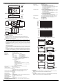
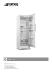
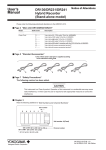
User's
Manual
• Although they are well-insulated, do not touch the instrument or any cables
connected to the instrument when voltage is being applied to them.
• When wiring to the sensor unit's primary current input terminal, tighten the
terminal screw to 20–30 N/m torque. If the tightening torque is too high,
damage to the terminal may result. If the tightening torque is too low, the
contact resistance at the point where current is applied to the terminal will rise,
and heat will be produced which can cause a fire. The terminal screw should be
periodically retightened.
• If the current capacity of the cables connected to the primary current input
terminal is small, heating can occur when large currents flow. Use a cable with
sufficient current capacity, and ensure that the temperature of the sensor unit's
primary current input terminal is below 100°C. Also ensure that the conductive
part of the cable does not protrude from the protective cover.
• Do not input excessive current as malfunction or damage may result .
• Do not carry the instrument by yourself
The instrument should only be carried by two persons. Firmly grasp the handles
on the side of the case. Model 751521 weighs 14 kg, and model 751523 weighs
24 kg. Take care to avoid injury while moving the instrument.
Always be sure to turn OFF the power switch and disconnect any cables (such
as power cables) before moving the instrument.
751521/751523
Current Sensor Unit
Thank you for purchasing the Current Sensor Unit (Model 751521/751523).
In order to take advantage of all the functions of the transducer and to ensure proper use, please read
this user's manual thoroughly before beginning operation.
This device is a current sensor with a 1500:1 current transformation ratio, that performs transformation
on the primary current. Please familiarize yourself with the functions and characteristics of the
instrument prior to operation.
7th Edition : May 2004 (YK)
All Rights Reserved, Copyright © 2001, Yokogawa Electric Corporation
3. Installation Position
IM 751523-01E
7th Edition
1. Checking the Contents of the Package
Unpack the box and check the contents before operating the instrument. If some items are
missing or otherwise inconsistent with the contents description, please contact your dealer or
nearest YOKOGAWA representative.
Model Code
751521
751523
751523 codes
Supply Voltage
Power Cord
Suffix Code
-10
-20
-30
-1
-3
-7
-D
-F
-R
-J
-H
Accessories:
WARNING
CAUTION
Note
• Desktop
Place the instrument on a flat, even surface as shown in the figure below. If the instrument is
installed in a horizontal position, rubber feet can be attached to prevent slipping. Two sets (four
pieces) of rubber feet are included in the package.
751523
751521
Specifications
600 A peak, DC/AC, 1500:1, single phase sensor unit
600 A peak, DC/AC, 1500:1, three phase sensor unit
U, V model
U, W model
U, V, W model
100 VAC
115 VAC
230 VAC
UL/CSA standard power cord
Maximum rated voltage: 125 V, maximum rated current: 7 A
VDE standard power cord
Maximum rated voltage: 250 V, maximum rated current: 10 A
AS standard power cord
Maximum rated voltage: 250 V, maximum rated current: 10 A
BS standard power cord
Maximum rated voltage: 250 V, maximum rated current: 5 A
GB standard power cord (complies with the CCC)
Maximum rated voltage: 250 V, maximum rated current: 10 A
• User's manual, 1 pc.
• Power cord: The type of power cord varies depending on the suffix code as folows:
-D:
UL/CSA standard power cord(part no. A1006WD), 1 pc.
-F:
VDE standard power cord(part no. A1009WD), 1 pc.
-R:
AS standard power cord(part no. A1024WD), 1 pc.
-J:
BS standard power cord(part no. A1023WD), 1 pc.
-H:
GB standard power cord(part no. A1064WD), 1 pc.
• Current secondary output cable (twist pair cable)
751521:
(part no. B8200JB), 1 pc.
751523-10:
(part no. B8200JA),2 pc.
751523-20:
(part no. B8200JA),2 pc.
751523-30:
(part no. B8200JA),3 pc.
• Spare fuse for the power supply (part no. A1463EF): 1 pc.
• Rubber feet (part no. A9088ZM): 2 sets (4 pcs.)
• Bolt (part no. Y9640RU): 751521, 4 pcs.; 751523, 6 pcs.
• Nut (part no. Y9121BU): 751521, 4 pcs.; 751523, 6 pcs.
• Washer (part no. Y9120WU): 751521, 4 pcs.; 751523, 6 pcs.
• Spring washer (part no. Y912OSU): 751521, 4 pcs.; 751523, 6 pcs.
Improper handling or use can lead to injury to the user or damage to the instrument. This symbol
appears on the instrument to indicate that the user must refer to the user’s manual for special
instructions. The same symbol appears in the corresponding place in the user’s manual to
identify those instructions. In the manual, the symbol is used in conjunction with the word
“WARNING” or “CAUTION.”
Describes precautions that should be observed to prevent serious injury or death to the user.
Describes precautions that should be observed to prevent minor or moderate injury, or damage to
the instrument.
Provides important information for the proper operation of the instrument.
Figure1 Installation Position
• Rack Mount
To mount the instrument in a rack, use the rack mount kit that is sold separately.
Product
Model
Rack Mount Kit for models 751521
Rack Mount Kit for models 751521
751535-E5
751535-J5
An outline of the attachment procedures is given below. For details regarding the attachment
procedures, see the instructions that are included with the rack mount kit.
1. Remove the handle on each side of the instrument.
2. Remove the four feet on the bottom of the instrument.
3. Remove the plastic rivet and the four seals covering the rack mount attachment holes on both
sides of the instrument near the front.
4. Place seals over the feet and handle attachment holes.
5. Attach the rack mount kit.
6. Mount the instrument on the rack.
Figure 2. Removing the Handles
Note
• When rack mounting the instrument, allow at least 20 mm of space around the vent holes to
prevent internal overheating.
• Make sure to have adequate support for the bottom of the instrument. However, do not block
the vent holes in the process.
• No rack mount kit is available for the model 751523.
4. Names of Parts
Front Panel
751521
Rear Panel
CURRENT SENSOR UNIT
CURRENT OUTPUT
100V AC
25VA MAX 50/60Hz
FUSE 250V T 6.3A
Power plug
POWER
WARNING
• Beware of electric shock
Do not perform measurement if the case is damaged.
Do not operate the device with wet hands, in a rainy or humid environment, or if
water droplets are present. Condensation may appear if sudden changes in
temperature occur. If this happens, let the device acclimatize to the new
temperatures for at least one hour, then refrain from using the device until
confirming that there is no condensation.
• Do Not Disassemble the Device
The device should be disassembled by qualified personnel only.
• Use the correct power supply
Before connecting the power cord, ensure that the power supply voltage
matches the supply voltage for the instrument, and that it is within the maximum
rated voltage for the power cord itself.
• Wire the secondary current output terminal to the measuring instrument before
supplying power to the unit.
• Do not disconnect the secondary current output terminal while power is being
supplied to the instrument.
• Do not apply primary current before supplying power to the device.
• To enable the protection features, check the following items before applying the
voltage or current of the item under measurement.
Check that the power supply is connected using the power cable provided with
the instrument, and that the instrument is grounded.
Check that the power switch of the instrument is turned ON.
Check that the protective covers that came with the instrument for the input and
output sections are attached.
• Wire the conductive part of the cable connected to the primary current input
terminal so that it does not protrude from the protective cover.
Secondary current
output terminal
Pilot Lamp
Power switch
Protective cover
Primary current
input terminal (out)
Primary current
input terminal (in)
Secondary current output terminal
Power plug
751523
Protective
cover
CURRENT SENSOR UNIT
CURRENT OUTPUT
100V AC
75VA MAX 50/60Hz
FUSE 250V T 6.3A
U
V
W
Primary current
input terminal (in)
POWER
Primary current
input terminal (out)
Pilot Lamp
Power switch
Figure3 Names of Parts
5. Operating Procedure
CAUTION
Ensure that the current flowing to the conductor of the object to be measured is
within the rated current range. If the rated current range is exceeded, the device
may overheat and become damaged.
1.
2.
3.
Connect the instrument's secondary current output terminal to the current input terminal on
the measuring instrument (power meter), and connect the power supply.
Set up the measuring instrument to match the specifications of the current transducer.
Carefully read the relevant user's manuals to obtain the correct procedure to make the
connections.
Wire the instrument's primary current input terminal to the measurement circuit.
IM751523-01E 7th Editon 1/2
Figures 4 and 5 provide a wiring example. Carefully read the user's manuals for the power
meter you are using to obtain the correct procedure to make the connections.
±
751521
Cable terminal
I
B8200JB (twist pair cable)
EL1
EL3
V A
V A
V
±
±
±
A
±
±
±
EL2
B8200JA
(twist pair cable)
Cable terminal
Power meter
Short-circuit wire*
B8200JA
(twist pair cable)
Cable terminal
± I ± I ± I
U V W
751523-30
* A short-circuit wire is not provided as an accessory.
Please supply your own wire.
Figure 4. An Example of Wiring a Power Meter to the Sensor Unit
Permitted Supply Voltage Frequency Range:
48 Hz to 63 Hz
Warmup Time:
Approximately 30 minutes
Insulation Resistance:
50 MΩ or more at 500 VDC
Across all input terminals together and the case
Across all input terminals together and the power plug
Across all input terminals together and all output terminals together.
Across the case and the power plug
Across all output terminals together and the power plug
Across each input terminal
Note: the “I” secondary current output terminal and “±” are shorted.
Withstanding Voltage:
AC 2200 V for one minute at 50/60 Hz
Across all input terminals together and the case
Across all input terminals together and all output terminals together
Across each input terminal
Across all terminals together and the power plug
Note: the “I” secondary current output terminal and “±” are shorted.
AC 1500 V at 50/60 Hz for one minute
Across the case and the power plug
Across all output terminals together and the power plug
Note: the “I” secondary current output terminal and “±” are shorted.
External Dimensions:
751521: Approx. 426(W) x approx. 221(H) x approx. 429.5(D) mm
751523: Approx. 426(W) x approx. 354.8(H) x approx. 429.5(D) mm
(excluding the input terminal, feet, and other protrusions)
Weight:
751521: approx. 14kg
751523: approx. 24kg
Power Consumption:
751521: Approx. 25 VA
751523: Approx. 75 VA
Primary current input terminal (out)
Primary current input terminal (in)
P
P
Pin
Pout
N
Nin
Nout
Maximum allowable
input current[Arms]
Battery
1000
N
Inverter
Single phase sensor unit
U V W
100
10
1
Uin
Vin
Win
Three phase sensor unit
Primary current
input terminal (out)
Uout
Vout
Wout
Motor
U
V
W
Figure 5. An Example of Wiring a Measurement Circuit
4.
5.
10
100
1000
10000
100000
Frequency[Hz]
Figure 6. Derating of the Input Current by Frequency
Burden resistance[Ω]
Primary current
input terminal (in)
Apply the primary current.
Read in the measured values.
The following calculation is used to determine the current flowing through the primary
conductor.
Example: Given a current of 100 mA being output from the instrument's secondary current
output terminal, 100 mA x 1500 = 150 A.
100
90
80
70
60
50
40
30
20
10
0
0.5Ω
0
50
100
150
200
250
300
350
400
450
500
550
600
Input Current[A]
Figure 7. Derating of the Input Current by Burden Resistance
Reverse
Note
• Never apply a current exceeding the allowable input range to the current input terminal of the
instrument. A current equivalent to the primary current rating may be output from the output
terminal even when the applied current is stopped. In that case, turn the power switch OFF
and then back ON again. Then, the instrument may return to normal once a current of the
allowable input range is applied. If it does not, contact your dealer or nearest YOKOGAWA
representative.
• The input current is limited by the burden resistance connected to the instrument's secondary
output as shown in figure 7.
• Avoid extremely strong external magnetic fields (aside from the magnetic fields that occur due
to the primary current of the item under measurement) as they may cause measurement
errors.
• Depending on the suffix code, some of the primary current input terminals on the rear panel of
the model 751523 cannot be used for measurement (for example, Vin, Vout, Win, and Wout).
For example, 751523-20 would be a "U, W" model, so the primary current input terminals Vin
and Vout could not be used for measurement.
CURRENT OUTPUT
100V AC
25VA MAX 50/60Hz
FUSE 250V T 6.3A
Front
13
426
13
7.5
429.5
221
CURRENT SENSOR UNIT
POWER
Input format
Rated Current
Output Current:
Input/Output Ratio:
Accuracy:
IM751523-01E 7th Editon 2/2
Figure 8. External Dimensions (751521)
Reverse
CURRENT OUTPUT
100V AC
75VA MAX 50/60Hz
FUSE 250V T 6.3A
U
V
W
Front
13
426
13
7.5
429.5
354.8
CURRENT SENSOR UNIT
POWER
Units:mm
20
Floating input, CT input
DC 0 to 600 A, AC 600 A peak
Primary rated current at 600 A is 400 mA.
1500:1
DC:
±(0.05% of reading+40 µA)
30 Hz ≤ f < 45 Hz
± (0.1% of reading+40 µA)
45 Hz ≤ f ≤ 68 Hz
± (0.05% of reading+40 µA)
66 Hz < f ≤ 1 kHz
± (0.1% of reading+40 µA)
1 kHz < f ≤ 40 kHz
± ((0.05% + 0.08 x f)% of reading+40 µA)
40 kHz < f ≤ 100 kHz
± ((0.2% x f)% of reading+40 µA)
However, the frequency of 1 kHz < f is merely a reference value.
The units for the calculation of f are kHz.
Standard Conditions
AC Input, Sine wave
23±5°C
30 to 70% RH
Input current: 2 A to600 A
Common mode voltage: 0 V
Power supply voltage: 95 to 105 V for code -1, 110 to 120 V for
code -3, 225 to 240 V for code -7
Test: at a frequency of 60 Hz, 50 Arms, the other frequency band
is 20 Arms.
Within 3 months after calibration
Accuracy 12 Months after Calibration:
Add the error in the reading value x 0.5 to the above accuracies.
Frequency Band:
DC to 100 kHz (–3dB)
Temperature Coefficient:
0.01%/°C (10 to 18°C,28 to 40°C)
Continuous Maximum Allowable Input:
600 A peak
Limited as shown in figure 6 when the frequency of the input current
exceeds 400 Hz. However, these are merely reference values.
Instantaneous Maximum Allowable Input:
3000 A peak 0.1 sec. or less (reference value)
Continuous Maximum Common Mode Voltage:
600 Vrms
Input Terminal Type:
M12 bolt, nut
Output Terminal Type:
Screw
Secondary Burden Resistance
90 Ω or less However, the burden resistance is limited by the input current
as shown in figure 7.
Operating Temperature:
10 to 40°C
Operating Humidity:
20 to 80% RH (no condensation allowed)
Storage Temperature Range:
0 to 60°C
Operating Altitude:
2,000 m or lower
Rated Supply Voltage:
100 VAC for code -1, 115 VAC for code -3, 230 VAC for code -7
Permitted Supply Voltage Range: 90 to 110 V for code -1, 105 to 125 V for code -3, 220 to 250 V for code -7
Rated Supply Voltage Frequency: 50 Hz/60 Hz
Units:mm
20
6. Specifications
Figure 9. External Dimensions (751523)
7.Servicing
If you encounter any problems during use, or if the device does not appear to be operating
normally, contact your dealer or nearest YOKOGAWA representative.
8.Warranty
If you experience a breakdown in the device due to faulty manufacturing or accidents during
shipping, contact your dealer or nearest YOKOGAWA representative.