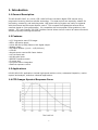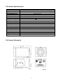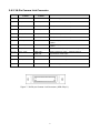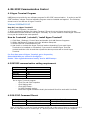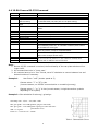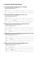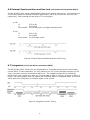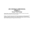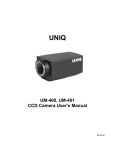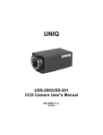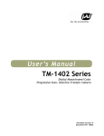
1
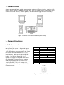
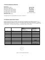
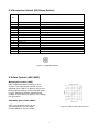
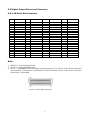
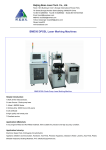
UNIQ
UP-610/UP-610CL
Digital CCD Camera
User's Manual
091-0610 V.1.0
08-06-03
Table of Contents
Warning
................................................................................................................. 2
Precautions
............................................................................................................ 2
Limited Warranty
1. Introduction
2. Camera Setup
................................................................................................... 2
....................................................................................................... 3
..................................................................................................... 5
3. Camera Functions
.............................................................................................. 5
4. RS-232C Communication Control
5. Digital Interface Timing
...........................…........................................ 10
..................................................................................... 12
6. Camera Functional Timing
................................................................................. 13
7. Camera Accessories
……………….............….......................................................... 15
8. Camera Malfunction
.......................................................................................... 16
9. Technical Support Information
.......................................................................... 17
1
WARNING
TO PREVENT FIRE OR ELECTRIC SHOCK HAZARD,
DO NOT EXPOSE THIS CAMERA UNIT TO RAIN OR MOISTURE.
DO NOT ATTEMPT TO REMOVE CAMERA COVER OR MODIFY THE CAMERA UNIT,
WARRANTY WILL BE VOIDED.
PRECAUTIONS
Do dot attempt to disassemble, modify, or repair the camera. Contact UNIQ for help.
Do not point the camera at bright objects, such as the sun, for a long period. It may
cause CCD blooming and permanent damages.
Do not operate the camera beyond the temperature range. Avoid using the camera
above 90% humidity.
Do not use unregulated power supply source.
Do not touch CCD glass cover with fingers or any hard objects other than professional
glass cleaning solvents.
Limited Warranty
UNIQ warrants to the original customer to be free from defects in material and
workmanship for two full years from the date of original purchase. This warranty covers
failures or damages due to defects in material or workmanship, which occur during
normal use. It does not cover damages or failures, which result from shipment,
mishandling, abuse, misuse, or modification.
A Return Material Authorization (RMA) number is required prior to returning any UNIQ
product for repair or replacement.
This proprietary document may not be reproduced or photocopied without the consent of
UNIQ. UNIQ makes no warranty or assumes no responsibility for any errors, which may
appear in this document. UNIQ reserves the right to make changes without notice or
obligation.
For immediate technical assistance, please call (408) 330-0818 or email to
[email protected]
2
1. Introduction
1.1 General Description
The UP-610/UP-610CL is a 10-bit, 659 x 494 full frame resolution digital CCD camera using
progressive scanning interline-transfer technology. The square pixels are especially suitable for
processing, measuring, and analyzing tasks. High speed moving objects can easily be captured
with the external asynchronous capture control. This compact and lightweight camera offers
excellent signal to noise performance. It’s compatible with most popular frame grabbers in the
market. The “user-friendly” RS-232C interface control allows users to control all camera functions
without physically touching the camera.
1.2 Features
•
•
•
•
•
•
•
•
•
•
•
•
•
1/3” Progressive scan CCD imager
659 x 494 active pixels
10-bit RS-644 (LVDS)/Camera Link digital output
Analog output
Full frame shutter (1/110 ~ 1/62,000 sec.)
<56 dB
Asynchronous reset at full frame shutter
110 Hz frame rate
40 MHz pixel clock
RS232C interface control
C-mount lens
Long-term frame integration
External exposure control
1.3 Applications
UP-610/UP-610CL applications include high-speed machine vision, automated inspection, motion
capture and analysis, and other industrial applications.
1.4 CCD Imager Spectral Response Curve
3
1.5 Camera Specifications
Model
CCD Sensor
Chip Size
Effective Pixels (H x V)
Unit Cell Size (H x V)
Pixel Clock
Frame Rate
Sync.
Digital Video Output
Analog Video Output
S/N Ratio
Min. Illumination
Gain
Gamma
Electronic Shutter
Lens Mount
Operating Temperature
Power Requirement
Dimension
Ext. Sync.
Asynchronous Reset
Weight
UP-610
UP-610CL
1/3” Hyper HAD progressive scan interline-transfer CCD
5.79 mm x 4.89 mm
659 x 494
7.4 µm x 7.4 µm
40 MHz (80 MHz for master clock)
110 FPS
HD: 55.554 KHz; VD: 110.0 Hz
10-bit RS-644/LVDS
Camera Link format
1 V p-p, 75ohm (BNC or 12 pin Hirose)
<56 dB
0.5 lux
MGC
1.0
1/110 ~ 1/62,000 selectable 16 steps
C-Mount
-10 °C ∼ +50 °C
12V DC, 280mA, 3.4W
50mm x 39mm x 83mm
Internal/External Auto Switch
Standard
200 g
1.6 Camera Dimension
4
2. Camera Setup
A basic camera and frame grabber system setup, as shown in Figure 1 below, requires a UP610/UP-610CL camera, a standard C-mount lens, a PS-12C power supply or equivalent, a PC
system and a VGA monitor, a frame grabber, and an external trigger device if necessary.
Figure 1. Camera and Frame Grabber System Setup
3. Camera Functions
3.1 12-Pin Connector
The 12-pin Hirose connector is located on the
rear panel of the camera. All ground signals
on pin 1, 3, 5, and 8 are common grounds.
+12 V DC input is recommended on pin 2, but
this camera should withstand +12 V ± 1V
input voltage. Make sure to set the NM/AM
switch to NM position for external HD and VD
locking. For HD (pin 6) and VD (pin 7)
inputs, TTL signals are required (see section
6.6 for details). For asynchronous capture
(VINT) applications, refer to section 6 for
details. For RS-232C interface control via this
12-pin connector, use pin # 10 and #12.
Figure 2 below shows a top view of the 12-pin
Hirose connector.
Pin No.
1
2
3
4
5
6
7
8
9
10
11
12
UP-610
UP-610CL
GND
+12V DC input
GND
Video
GND
External HD
N/C
Ext. VD/VINT
N/C
GND
N/C
RX (RS-232C)
N/C
Integration control
TX (RS-232C)
N/C
Figure 2. 12-Pin Hirose Connector
5
3.2 Mode Switches Selection
Designation:
NS-Functional select
DS-Shutter speed select
NR-Reserved for custom options
RI- Reserved for custom options
NP- Reserved for custom options
PS- Reserved for custom options
NM-Normal mode
AM-Asynchronous mode
Figure 3. Mode switches
Timing details of the mode switches are shown in section 6.
3.3 Shutter Speed Dial Switch
Shutter speed dial switch is located on the rear panel and there are 16 different positions. To
select camera gain, reference, or to save a user page, set NS/DS switch to NS position. To adjust
shutter speed, set NS/DS to DS position. For normal shutter speed, make sure to set NM/AM mode
to NM location. For asynchronous capture, set NM/AM mode to AM location.
Position No.
Functional Select (NS)
0
1
2
3
4
5
6
7
8
9
A
B
C
D
E
F
Normal
Gain Adjustment
Reference Adjustment
Factory Page
User Page 1
User Page 2
User Page 3
User Page 4
Normal Speed/Double Speed
Reserved
Reserved
Reserved
Reserved
Reserved
Reserved
Reserved
Shutter Speed Select (DS)
Shutter
Asynchronous
Speed (sec)
Capture (sec)
(NM Mode)
(AM Mode)
1/110
1/110
1/220
1/220
1/440
1/440
1/900
1/900
1/1,800
1/1,800
1/3,500
1/3,500
1/7,000
1/4,500
1/9,000
1/7,000
1/14,000
1/9,000
1/18,000
1/14,000
1/22,000
1/18,000
1/28,000
1/22,000
1/37,000
1/28,000
1/55,000
1/37,000
1/110,000
1/55,000
Pulse Width Control
1/110,000
Figure 4. Shutter Speed Dial Switch
6
3.4 Momentary Switch (UP/Down Switch)
Position
No.
Functional Select (NS)
0
1
2
3
4
5
6
7
8
9
A
B
C
D
E
F
Normal
Gain Adjustment
Reference Adjustment
Factory Page
User Page 1
User Page 2
User Page 3
User Page 4
Normal speed/Double speed
Reserved
Reserved
Reserved
Reserved
Reserved
Reserved
Reserved
Up/Down Switch
N/A
Move up or down to adjust gain
Move up or down to adjust reference
Move up or down to recall factory page
Up: Recall; Down: Save
Up: Recall; Down: Save
Up: Recall; Down: Save
Up: Recall; Down: Save
Up: Normal speed; Down: Double speed
Figure 5. Up/Down Switch
3.5 Gain Control (AGC/MGC)
Manual gain control (MGC)
MGC is standard factory setting on this
camera. The manual gain control can be
adjusted from 9 dB to 18 dB only due to the
factory default setting of AGC and AGC MAX
control. Adjusting the gain potentiometer
located on rear panel, in figure 6, will change
the gain value.
Automatic gain control (AGC):
AGC is not available and it is not
recommended to use by UNIQ.
Contact UNIQ for further details
Figure 6. AGC Control Characteristics
7
3.6 Digital Output Pinout and Connector
3.6.1 40-Pin D-Sub Connector
PIN
SIGNAL
I/O
1
2
3
4
5
6
7
8
9
10
11
12
13
14
15
16
17
18
19
20
+12VIN/OUT
GND
CLK+
CLKFEN+
FENLEN+
LENDATA0+
DATA0DATA2+
DATA2DATA4+
DATA4DATA6+
DATA6DATA8+
DATA8RESERVED
RESERVED
I/O
O
O
O
O
O
O
O
O
O
O
O
O
O
O
O
O
NOTE
PIN
SIGNAL
RS644/LVDS
RS644/LVDS
RS644/LVDS
RS644/LVDS
RS644/LVDS
RS644/LVDS
RS644/LVDS
RS644/LVDS
RS644/LVDS
RS644/LVDS
RS644/LVDS
RS644/LVDS
RS644/LVDS
RS644/LVDS
RS644/LVDS
RS644/LVDS
21
22
23
24
25
26
27
28
29
30
31
32
33
34
35
36
37
38
39
40
RESERVED
RESERVED
HD
GND
VD / VINT
RESERVED
INT
RESERVED
DATA1+
DATA1DATA3+
DATA3DATA5+
DATA5DATA7+
DATA7DATA9+
DATA9RESERVED
RESERVED
I/O
NOTE
I
TTL
I
TTL
I
TTL
O
O
O
O
O
O
O
O
O
O
RS644/LVDS
RS644/LVDS
RS644/LVDS
RS644/LVDS
RS644/LVDS
RS644/LVDS
RS644/LVDS
RS644/LVDS
RS644/LVDS
RS644/LVDS
Note:
1. DATA9+/- is most significant bits.
2. DATA0+/- is least significant bits.
3. Pin #1 (+12VIN/OUT) of 40-pin digital connector and pin #2 (+12V) of 12-pin Hirose connector
are connected. If 12V power is provided from 12-pin connector, pin #1 of the 40 pin connector
will act as a +12V output.
Figure 7. 40 pin digital connector
8
3.6.2 26-Pin Camera Link Connector
PIN NO.
1, 14
CAMERA LINK
SYMBOL
INNER SHIELD
UNIQ CAMERA
SYMBOL
SHIELD
FUNCTION
Inner shielding
2, 15
X0-, X0+
DATA0-, DATA0+
Video, LEN and FEN data output
3, 16
X1-, X1+
DATA1-, DATA1+
Video, LEN and FEN data output
4, 17
X2-, X2+
DATA2-, DATA2+
Video, LEN and FEN data output
5, 18
Xclk-, Xclk+
CLK-, CLK+
Pixel clock output
6, 19
X3-, X3+
DATA3-, DATA3+
Video, LEN and FEN data output
7, 20
SerTC+, SerTC-
Rx+, Rx-
8, 21
SerTFG-, SerTFG+
Tx-, Tx+
9, 22
CC1-, CC1+
HD-, HD+
Differential pair, serial communications from frame
grabber
Differential pair, serial communications to frame
grabber
Camera Control 1 (CC1) - Horizontal signal input
10, 23
CC2+, CC2-
11, 24
CC3-, CC3+
VINT/VD+,
VINT/VDReserved
Camera Control 2 (CC2) - Vertical signal or
asynchronous reset input
Reserved for custom options
12, 25
CC4+, CC4-
Reserved
Reserved for custom options
13, 26
INNNER SHIELD
SHIELD
Inner shielding
Figure 7. 3M 26-pin Camera Link Connector (MDR-26 pin)
9
4. RS-232C Communication Control
4.1 Hyper Terminal Program
UNIQ does not provide its own software program for RS-232C communication. In order to use RS232C interface, a Hyper Terminal software program must be installed and applied. The following
shows how to run and use of Hyper Terminal.
Windows 95/98/Me/2000/XP
How do I run Hyper Terminal?
1. Click Start / Programs / Accessories
2. Within accessories double click Hyper Terminal (If you do not see Hyper terminal click the
communications folder and then click Hyper Terminal). If you are unable to locate Hyper Terminal
it may not be installed see next question.
How do I uninstall / reinstall / install Hyper Terminal?
1.
2.
3.
4.
Click Start / Settings / Control Panel and double click Add Remove Programs.
Within Add Remove Programs click the Windows Setup tab.
Double click the communications icon.
And check or uncheck the Hyper Terminal section depending if you want Hyper
Terminal to be installed or uninstalled, if you want to reinstall Hyper Terminal
uncheck and then click ok and then repeat the above process and re-check Hyper
Terminal.
For first time user of Hyper Terminal, go to Properties,
Select 9600 bits per second in Configure…
Enable “Echo typed characters locally” box in ASCII setup…
4.2 RS232C communication setting requirement:
Baud Rate
Parity
Data
Start Bit
Stop Bit
Xon/Xoff
Go to
-
9600 bps
None
8 bit
1 bit
1 bit
None
Hyper Terminal program
Click File and click Properties
Click Settings tab
Click ASCII Setup…
In ASCII Sending section,
check Echo typed characters locally but uncheck Send line ends with line feeds
4.3 RS-232C Command Pinout:
Command
TX
RX
12-pin Hirose Connector
Pin #12
Pin #10
40-pin Digital Connector
Custom request only
Custom request only
Note: If RS-232C is via 9-pin D-sub connector at PC end, make sure to short or connect pin # 4
and # 6, and then short or connect pin # 7 and #8, but do not connect all 4 pins together.
10
4.4 10-Bit Camera RS-232 Command
Command
?
ru#
rp
sm#
Command Name
Error
Recall user page
Report current
camera setting
Recall factory setting
page
Shutter mode
sp#
Save user page
ns
ds
nm
am
Normal speed
Double speed
Normal mode
Asynchronous mode
Refer to camera specifications
Refer to camera specifications
gi###
Gain increase
gd###
Gain decrease
gn###
Gain number
bi###
bd###
bn###
Reference increase
Reference decrease
Reference number
### = Hexadecimals (000 ~ 3ff). If no number entered, gain will
be increased by factor of 1. If a number is entered, then number
will be added to stored gain
### = Hexadecimals (000 ~ 3ff).
Same as gi above, except it will be decreased.
### = Hexadecimals (000 ~ 3ff).
Refer to the example shown below.
### = Hexadecimals (000 ~ 3ff). If no number entered, reference
will be increased by factor of 1. If a number is entered, then
number will be added to stored reference
rf
Notes
“?” Error will appear on screen if incorrect command is entered
Must have a number after “ru” such as 1, 2, 3 or 4
G = Gain; R = Reference
S = Shutter Mode; NS, NM (refer to rear plate setting)
Must have a number after sm (1 ~ F), refer to user manual for
details.
There are 4 user page available
Note:
1. Once a RS-232 command is received, the functionality of the rear plate switches will no
longer valid.
2. All command has to be in “lower case.”
3. All numbers have to be in “hex” format, use a PC calculator to convert between hex and
decimal numbers if necessary.
Example 1:
User Enter: “sm5” (shutter speed at 5)
Camera return: “?” or “3f” in Hex
(incorrect answer, no RS232C communication or something’s wrong)
or
Camera return: “ ” or “1” in Hex (correct answer, it might show other symbols
depending on PC system)
Example 2: Gain calculation for above gi, gd and gn.
Gain Range: 000 ~ 3ff, 0V ~ 5.0V; 8dB ~ 38dB
Min. gain: gn000 = 0V at 8dB (gn000 or gn0 gives same result)
Max. gain: gn3ff = 3V at 38dB (gn99a or gn3ff gives same result since
gain saturates at 3V)
9dB = 1V or gn333
Factor of 1 = 1/1024 or 1/3ff = 4.88mV
Table 1. Camera Gain Curve
11
5. Digital Interface Timing
5.1 Pixel Clock
5.2 Line Enable
5.3 Frame Enable
Note:
1. Pixel clock = 40MHz
2. 1 N = 25 nsec
3. 1 H = 718 N
12
6. Camera Functional Timing
6.1 Free Run (Shutter Speed position 0, 110 fps)
Mode switch setting: NS, NR, NP, NM
Shutter speed dial setting: 0
6.2 Free Run (Shutter speed position from 1 to F)
Mode switch setting: NS, NR, NP, NM
Shutter speed dial setting: 0 to F
6.3 Asynchronous Capture (Shutter speed position 0)
Mode switch setting: NS or DS, NR, NP, AM
Shutter speed dial setting: 0
6.4 Asynchronous Capture (shutter speed position from 1 to E)
Mode switch setting: NS or DS, NR, NP, AM
Shutter speed dial setting: 1 to E
6.5 Asynchronous Capture with Pulse Width Control
Mode switch setting: NS or DS, NR, NP, AM
Shutter speed dial setting: F
13
6.6 External Synchronization and Gen-lock (via Camera Link interface ONLY)
The UP-610/UP-610CL camera automatically locks to the external sync source. The external sync
source must match the camera HD and VD specification, which are 55.554 KHz and 110.0 Hz
respectively. Both external HD and VD are TTL level signals.
a) HD
H:
L:
Pulse width:
2.5V to 5V
0V or GND
5-50% duty cycle, see figure 8 shown below.
H:
L:
Pulse width:
2.5V to 5V
0V or GND
0.5-50% duty cycles
b) VD
Figure 8. External Synchronization and Gen-lock Timing
6.7 Integration (via 12-pin Hirose connector ONLY)
The UP-610/UP-610CL camera can be integrated up to 2 seconds without severe noise or dark
current effect. To start integration, pin #11 (same as pin #27 of 40-pin digital connector) of the
12-pin connector must be connected to GND or 0V. The integrated video will be shifted out
following the next vertical drive after pin #11 goes back to high or 5V level, as shown in figure 9
below. If a frame grabber does not capture the immediate frame or integrated video, the normal
video (before the integration) will display again on the monitor.
Figure 9. Integration Control Timing
14
7. Camera accessories
7.1 Power Supply and Power Cable
12 V DC regulated power supply with 1A current output or better is recommended. This camera
uses Hirose 12-pin connector for power source. The matting cable plug connector can be
purchased through distributors or UNIQ and the Hirose part number is HR10A10P12S. UNIQ
provides power supplies and power cables as "one stop shopping" for customers. Alternatively, the
power supplies and power cables can be purchased through power supply and cable vendors.
Contact UNIQ for vendor list.
7.2 Lens
C-mount lens is the standard lens for UP-610/UP-610CL camera. There are a variety of C-mount
lenses in the market that works with UP-610/UP-610CL camera. Make sure the quality and
specification of the lens match the camera's application. Some of the most popular lenses in the
market, such as Cosmicar, Fujinon, Rodenstock, and Schneider, are recommended.
7.3 Digital Connector and Cable
UP-610/UP-610CL utilizes high quality, subminiature D-sub connectors and very flexible twisted
paired, overall shielded cable for interfacing UP-610/UP-610CL digital camera and frame grabbers.
Lists of UP-610/UP-610CL camera and various frame grabbers cable pinout are available. UNIQ
also stocks all custom cables for customer's conveniences. Contact us for more details.
The mating cable plug connector and back shell kits can be obtained through AMP.
AMP: 749111-3 cable plug connector with covers.
AMP: 749192-1 back shell kits with latches
15
8. Camera Malfunction
WARNING: DO NOT ATTEMPT TO OPEN THE CAMERA HOUSING IN ANY CASE WITHOUT
CONSENTING THE FACTORY.
Camera malfunction rarely happens. In case camera malfunctions, the following troubleshooting
procedures would help to minimize the problem; it definitely helps the user to find out the actual
problem and may save a trip for sending the camera back to the factory.
a) First of all, unplug the power supply and disconnect the 12-pin Hirose power connector and any
attached cable(s) from the camera unit. Make sure there is nothing connected to the camera at this
time.
b) Close all necessary frame grabber software files on the computer.
c) Check the 12V DC power supply at the 12-pin connector cable and make sure it does provide the
correct voltage to the 12-pin connector. If it does not, replace a good power supply and proceed
the following steps.
d) Make sure to set the camera shutter dial switch and mode switches at the correct position (refer
to section 4, timing signals, for details.)
e) Now, power up the camera with frame grabber cable(s) connected to the camera and the frame
grabber. Click on UP-610/UP-610CL configuration file from the frame grabber's configuration file
list. If all the above camera and frame grabber setup procedures are done correctly, a good image
should be appeared on a display monitor.
f) If it fails to show any good images, check the interface cable pinouts, both camera and frame
grabber end, consult UNIQ or frame grabber manufacturer if necessary. Also, make sure the UP610/UP-610CL camera configuration file is correct.
g) If problem still exits, contact UNIQ or frame grabber manufacturer for further assistance.
h) If live video does exit but it's not good or clean, check frame grabber configuration file settings
or contact UNIQ or frame grabber manufacturer for assistance.
i) " I do get the video but it's too dark." Make sure the lens is wide open and shutter speed dial
switch is at "no" shutter or "low speed" shutter.
J) Point the camera at a bright scene without a lens on, a blank or bright display should be seen on
a display monitor. Covering the CCD camera with hand or lens cap should see a dark video. If no
video occurs, most likely the CCD camera is damaged, assuming that all setup procedures were
done correctly above. Consult camera technical support at the factory.
k) If there is a good video but it is not clean or bad, it is possible that the CCD imager glass is
dirty, or the CCD camera could be partially damaged. Use high-pressure air to blow the dirt away
on the CCD protective glass surface if the CCD glass is not clean. If the problem still exists,
contact the UNIQ technical support for help.
16
l) If there is a good video but the RS232C communication fails, or if the camera does not respond
after sending a command, make sure to check the following.
i)
ii)
Go to Hyper Terminal program
Click File and click Properties
Click Settings tab
Click ASCII Setup…
In ASCII Sending section, check Echo typed characters locally but uncheck Send line
ends with line feeds
If RS-232C is via 9-pin D-sub connector at PC end, make sure to short or connect pin # 4
and #6, and then short or connect pin # 7 and #8, but do not connect all 4 pins
together.
9. Technical Support Information
For technical assistance, contact UNIQ Technical Support or Applications Engineer at
Phone:
Fax:
Email:
(408) 330-0818
(408) 330-0886
[email protected]
Company contact information:
UNIQ VISION, INC.
3442 De La Cruz Blvd.
Santa Clara, CA 95054
Phone:
Fax:
(408) 330-0818
(408) 330-0886
Our website:
Sales Inquiries:
Technical Support:
www.uniqvision.com
[email protected]
[email protected]
17