1
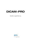
DiCAM-PRO
Operating Instructions
The COOKE Corporation
1091 Centre Road, Suite 100
Auburn Hills, MI 48326-2670
Tel: (248) 276-8820
Fax: (248) 276-8825
[email protected]
www.cookecorp.com
April 2002
DiCAM PRO Manual
2
Safety Instructions
For your own safety and in order to guarantee a safe operation of the
camera, please read carefully the following information prior to using the
device.
-While operating with the camera system please be careful that the image intensifier is not over exposed.
While not using the camera, protect it by using a lens cap.
-Never operate the camera at places where water or dust might penetrate.
-Place the camera on a sufficiently stable basis.
Shocks like e.g. dropping the camera onto the floor might cause serious damage to the device. Therefore exclusively the tripod attachment
at the bottom side should be used for mounting the camera.
-Always unplug the camera before cleaning it. Do not use cleaning liquids or sprays. Instead, use a dry, soft duster.
-Never insert any objects through the device's slots. The applied voltage
inside the camera can cause short-circuits or electrical shocks.
-The slots in the camera housing (bottom and rear panel) are needed for
ventilation. In order to guarantee a proper operation and to prevent
overheating of the camera, these slots must always be kept free.
-Make sure that the connecting cable is in good condition and that the
link to the socket does not represent an obstacle.
-Detach the camera and contact the customer service in the following
cases:
-When cable or plug is damaged or worn-out.
-When water or other liquids have soaked into the device.
-When the device is not properly working although you followed all
instructions of the user's manual.
-When the camera fell to the floor or the housing has been damaged.
-When the device shows apparent deviations of normal operation.
The COOKE Corporation
1091 Centre Road, Suite 100, Auburn Hills, MI 48326-2670
Tel: (248) 276-8820 Fax: (248) 276-8825 [email protected], www.cookecorp.com
DiCAM PRO Manual
3
Contents
1. Installation and Powering Up
1.1
Computer
System Requirements
Graphic Setup
Installing the PCI-Board
5
5
5
6
1.2
Installation of the Hardware Driver
Installation under Windows 9x/ME/2000
Installation under Windows NT
Installation under Linux
7
7
7
7
1.3
Installation “CamWare”
8
1.4
Camera and PCI-Board
Serial Data Transfer via FOL
9
9
1.5
Lens Mount
10
1.6
Powering Up
11
2.
Functional Principle
2.1
2.2
Block Diagram and Internal Data Stream............... 12
Principles of the Image Intensification................... 14
Photocathode........................................................... 14
Micro Channel Plate................................ .................. 15
Phosphor Screen................................ ...................... 15
3.
Timing
3.1
3.2
3.3
DiCAM-PRO in Single Trigger Mode ........................... 18
DiCAM-PRO in Multi Trigger Mode ............................. 20
DiCAM-PRO in Double Trigger Mode .......................... 22
4.
Trigger Control
Electrical Trigger Input............................................... 24
Optical Trigger Input ................................ .................. 24
BNC Socket on the PCI-Board................................... 24
5.
Control Signals
GATE OUT output signal........................................... 25
GATE DIS input signal ................................ .............. 25
Jack Plug Socket at the PCI-Board ............................ 25
LED at the PCI-Board................................................ 26
The COOKE Corporation
1091 Centre Road, Suite 100, Auburn Hills, MI 48326-2670
Tel: (248) 276-8820 Fax: (248) 276-8825 [email protected], www.cookecorp.com
DiCAM PRO Manual
4
6.
Software
Application Software CamWare
Plug-Ins
Software Development Kit (SDK)
Twain Drivers
7.
Servicing, Maintenance and Cleaning
Instructions
Servicing, Maintenance & Cleaning Instructions
Cleaning Method for the Optical Part
Cleaning Method for the FOL
8.
27
27
27
27
28
28
29
Appendix
Customer Service
Warranty
CE-Certification
Dimensions and Weight
System Data
30
30
30
31
32
The COOKE Corporation
1091 Centre Road, Suite 100, Auburn Hills, MI 48326-2670
Tel: (248) 276-8820 Fax: (248) 276-8825 [email protected], www.cookecorp.com
DiCAM PRO Manual
5
1. Installation and Powering Up
The DiCAM-PRO imaging system consists of camera and PCI-Board.
To get the system working properly, follow the instructions.
1.1 Computer
System Requirements
The PCI-Board should be installed in a computer with following characteristics:
-PCI-Bus with PCI-Chip Version 2.1 or higher
-Intel Processor, Pentium or AMD
-128 MB RAM
-Possible Operating Systems
-Microsoft Windows 95 Version 4.00.950b or higher
-Microsoft Windows 98 or 98SE
-Windows ME
-Microsoft Windows NT 4.0 Workstation
-Microsoft Windows 2000 Works tation
Please contact COOKE for more information on Linux support for our
cameras.
Note:
Drivers for our cameras are optimized for best performance. This may
have implications for some dual-processor systems. If you are planning
to use a dual processor computer in your imaging application, please
contact Cooke technical suport for more information
Graphic Board
For best display of images on the monitor we recommend the use of
highest performance boards with at least 4MB RAM, preferable with AGP
Bus architecture.
Graphic Setup
The camera generates 12 Bit (4096 grey levels). For display on the PC
Monitor 8 Bit (256 grey levels) respectively 3x8 Bit in true color (16,7 millions colors) are generated.
In general, several graphic setups are possible. We recommend the setting with 24 or 32 Bit with 16.7 million colors.
In Windows, use the “settings” tab in the “Display Properties” to set “colors” to at least 24 bit, and “size” the desktop to 1024 x 768.
The COOKE Corporation
1091 Centre Road, Suite 100, Auburn Hills, MI 48326-2670
Tel: (248) 276-8820 Fax: (248) 276-8825 [email protected], www.cookecorp.com
DiCAM PRO Manual
6
Installing the PCI-Board
Caution! Before touching the PCI-Board make sure you have not accumulated
static charges. A discharge may destroy the sens itive electronics and
voids any guarantee.
Insert the PCI-Board in a free PCI-slot of your computer and screw the
bow onto the PC housing.
Make sure the board does not touch any electrical conducting parts
(housing, other boards, wires or chillers)
It is essential to use a master PCI-slot. Some computers require additional enabling of PCI-slot mastering on BIOS level.
The COOKE Corporation
1091 Centre Road, Suite 100, Auburn Hills, MI 48326-2670
Tel: (248) 276-8820 Fax: (248) 276-8825 [email protected], www.cookecorp.com
DiCAM PRO Manual
7
1.2 Installation of the Hardware Driver
You can operate the camera with Windows9x/ME/2000/NT or Linux.
Installation under Windows 9x/ME/2000
New-Installation of the hardware driver
If you have Windows9x/ME or Windows 2000 installed, the computer
should automatically recognize the new hardware (PCI-Board) and request you to insert a disk with the manufacturer's drivers.
See the “Quick Install Guide” supplied with your CD for more details.
Updating the hardware driver
For updating an existing driver, please download the newest driver version from the internet under http://www.cookecorp.com.
For installation please read the actual information in the readme.txt file,
which will be, download automatically with the driver.
In case the downloaded drivers are compressed you have to decompress them with a suitable program (e.g. ZIP program).
Installation under Windows NT
Installation of the Hardware Driver
If you install the camera under Windows NT, you need the rights of the
administrator. Please login as administrator.
See “Quick Install Guide” for more information.
Installation under Linux
Please contact COOKE customer support for more information on
Linux support for our cameras.
The COOKE Corporation
1091 Centre Road, Suite 100, Auburn Hills, MI 48326-2670
Tel: (248) 276-8820 Fax: (248) 276-8825 [email protected], www.cookecorp.com
DiCAM PRO Manual
8
1.3
Installation of the Software “CamWare”
CamWare is a 32 Bit Windows application. With CamWare all camera
parameters can be set. The images can be displayed on the monitor
and saved on hard disk. For detailed information please see the separate manual “CamWare”.
You will find the software CamWare on the enclosed CD. The newest
version can also be downloaded from the internet under
http://www.cookecorp.com.
Installation from CD
Refer to the “Quick Install Guide” supplied with your DiCam Pro for details on software installation.
Installation from Internet Download CamWare from the Internet to a free selected directory. The
downloaded file must be decompressed with a suitable program (e.g. ZIP
program) Start the installation with “setup.exe”.
The newest information how to install CamWare can be found in the “readme.txt” file.
To install CamWare under Windows 2000 and Windows NT you need
administrator privileges.
Remark
After successful installation the computer has to be restarted.
The installation program transfers all necessary DLL and OLE files to the
respective Windows, checking automatically for existing older versions
and replacing them by new ones.
Windows’95 carries out all “registry“-entries.
If the program is to be deleted from the computer, a proper de-installation
is carried out in
S TART - S ETUP - S YSTEM CONTROL - SOFTWARE
After successful installation you will have the new directory ‘Digital Camera Toolbox’. CamWare and some additional useful tools will be installed
to this directory.
Hotline
In case you have problems during installation, call our hotline (see “Customer Service“).
The COOKE Corporation
1091 Centre Road, Suite 100, Auburn Hills, MI 48326-2670
Tel: (248) 276-8820 Fax: (248) 276-8825 [email protected], www.cookecorp.com
DiCAM PRO Manual
9
1.4 Camera and PCI-Board
Before Powering Up, make following connections:
-Power from Power Supply to Camera
-Serial Interface between camera and PCI-Interface-Board with enclosed cables.
For the serial data transfer between camera and PCI-Interface-Board a
fiber optic cable (FOL) is used.
Fiber Optic Link (FOL)
Remove the protective caps from the camera and the PCI-InterfaceBoard. Also remove gently the small caps from either end of the cable.
Plug in the cable on both devices. Because of the plug shape the c ables
cannot be mixed up. The plugs should slip in easily. Do not force!
Caution! Avoid kinking or bending the cable over a sharp edge, this will break the
core and destroy the cable. Do not step on the cable, avoid touc hing the
ends with bare fingers and replace the caps on either the cable or camera / board to protect the sensitive optical surfaces from dust when not in
use.
The small protection caps will be lost easily. Keep the caps on a safe
place.
The COOKE Corporation
1091 Centre Road, Suite 100, Auburn Hills, MI 48326-2670
Tel: (248) 276-8820 Fax: (248) 276-8825 [email protected], www.cookecorp.com
DiCAM PRO Manual
10
1.5 Lens Mount
Lens Mount
Remark
The standard DiCAM-PRO lens adapter is for Nikon lenses (F-Mount).
This adapter is fixed with three small Allen screws. Other adaptors are
available for C-mount and custom lenses.
C-Mount lenses are not recommended in combination with 25mm intensifiers because the photo cathode will not completely filled.
Focal length
Focal length
Focal length
Fiber Optic
Focal
Plane
Fiber Optic
Image
Intensifier
DEP
DEP
Hamamatsu
?
[mm]
18
25
28
input
window
glass
glass
glass
l (air)
[mm]
g (glass)
[mm]
Nd
6,2? 0,5
5,9? 0,2
6,2? 0,8
1,47
1,47
-
Hamamatsu
DEP
Hamamatsu
25
18/25
18/25
glass
FO
FO
6,0? 1,5
9,5
9,5
5,55? 0,2
6,0?0,1
5,5?0,4
5,9?1,0
-----
Glass
Glass Plate
Focal
Plane
-
Front plate with placing of the image intensifier
The COOKE Corporation
1091 Centre Road, Suite 100, Auburn Hills, MI 48326-2670
Tel: (248) 276-8820 Fax: (248) 276-8825 [email protected], www.cookecorp.com
DiCAM PRO Manual
11
1.6 Powering Up
Before using the DiCam for the first time:
-Install the PCI-Interface-Board properly mounted?
-Connect the Camera to board connection via fiber optic cable
-Connect the power supply connected to camera and the AC
-Mount the lens on the camera
-Put protective cap on the lens
Switch on the computer
Switch the computer on but do not start yet CamWare
Switch on the camera
Switch the camera on by pressing the POWER button on the rear panel
of the device.
When properly attached, the LED will flash red-green for approx. 3 minutes. During this time, the sensor is cooled down to a temperature of
approx. -12 degrees Centigrade (5 degrees Fahrenheit).
Subsequently, the diode will change to permanently green, indicating
that the correct operation temperature has been reached and that you
can now start measuring. If the diode shows a permanent red, a hardware error has occurred.
The following table lists possible reasons for hardware errors.
Possible states of the LED
LED color
red continuous
red/green intermittent
Green continuous
Starting CamWare
Status
Hardware error!
?? Connection of Camera and PCI-Board interrupted
?? Defective cable
?? Computer off
?? Temperature on CCD sensor above 65?C
(causing automatic camera switch off)
System ready, however CCD has not yet reached its optimum temperature (-11 … -15?C). After a few minutes LED should change to
continuous green.
If the intermittent state is going on constantly, there could be a problem with the cooling. In this case please contact COOKE.
System ready!
Now start “CamWare“ from the directory
– Digital Camera ToolBox.
For detailed information to CamWare please see the separate manual
“CamWare”.
The COOKE Corporation
1091 Centre Road, Suite 100, Auburn Hills, MI 48326-2670
Tel: (248) 276-8820 Fax: (248) 276-8825 [email protected], www.cookecorp.com
DiCAM PRO Manual
12
2. Functional Principle
The images, captured by the camera head, are transferred via a highspeed data transfer to the PCI-Board in the computer. The data are
saved in the RAM of the computer where the operator can decide what to
do with them.
With the camera control software “CamWare” the camera can be controlled within the windows environment and the images can be displayed
on the monitor.
The Recorder function allows you to record image sequences and display them as "movies".
The maximum memory space for the recorded images depends solely
on the RAM size of your computer.
When starting the program, the software automatically recognizes the
camera type.
For detailed information please see the “CamWare” manual.
2.1 Block Diagram and Data Stream
Block Diagram
In the following block diagram the structure of the complete camera system is shown.
The COOKE Corporation
1091 Centre Road, Suite 100, Auburn Hills, MI 48326-2670
Tel: (248) 276-8820 Fax: (248) 276-8825 [email protected], www.cookecorp.com
DiCAM PRO Manual
13
Internal Data Stream of black/white came ras
The PCI-Board gets the 12bit data from the camera and transfers it via
PCI-Bus to a 16bit array (of the PC Memory). The higher 4bits are set to
zero. The 16bit data are automatically converted to an 8bit array and accessed by the graphic board. Depending on the graphic mode graphics
are displayed as 8, 24 or 32 bit depth.
File Formats
The command ‘Export’ stores 16bit or 8bit data on hard disk in B16,
TIFF, FITS, BMP, or ASCII format.
For further information see Chapter 2.3.
Display
The camera ac quires 12 bit images, with 4096 (2E12) grey levels between black and white. However the monitor display of the image is limited to 8 bit and therefore to 256 (2E8) grey levels.
The command ‘Convert Control’ allows to select a range between 0 ...
4095 grey levels, which is then displayed in 256 grey levels on the PC
monitor.
PC
Monitor
Camera
PCI-Interface-Board
Graphic Board
PCI-Bus
The COOKE Corporation
1091 Centre Road, Suite 100, Auburn Hills, MI 48326-2670
Tel: (248) 276-8820 Fax: (248) 276-8825 [email protected], www.cookecorp.com
DiCAM PRO Manual
14
2.2 Principles of the Image Intensification
The DiCam Pro achieves high gain and short gating times through the
use of an image intensifier (see diagram below).
-180V/+80V
0 ... 900V
shutter on/off
gain
6kV
acceleration voltage
light
e
-
-
e
light
object
lens
photocathode
connected to a pulser,
e.g. HVP5N, HVP2N
MCP
micro channel plate
phosphor screen
connected to a high voltage
power supply, e.g. HVMCP
Light emitted from an object releases photoelectrons at the photo cathode. The photoelectrons enter the channels of a micro channel plate
(MCP) where they are multiplied producing secondary electrons. Finally
the accelerated electrons hit a phosphor screen, producing light emission.
Photocathode
The photo cathode consists of a thin layer of a material with low activation energy for electrons and allows high quantum efficiency down to long
wavelength.
Choosing the right material and layer thickness the spectral sensitivity
can be varied from the near UV to the near infrared. The quantum efficiency (number of photoelectrons to number of photons) of many materials is as high as 10% or even above. By applying a voltage to the photo
cathode, electrons are either pushed towards the MCP (negative voltage)
or back to the photo cathode (positive voltage).
This property of the intensifier makes it particularly suited as an electronic shutter. Although several kilovolts are required to operate the intensifier, a change of a few hundred volts can cause the device to effectively switch on or off. A potential difference of 200-250 V at the photo
cathode is sufficient to achieve a shutter ratio of 1:107.
High performance ‘high voltage’ generators achieve gate times of a few
nanoseconds. The capacitive load (approx. 100pF) of the photo cathode
is switched with a rise and fall time of 1-2 ns.
The COOKE Corporation
1091 Centre Road, Suite 100, Auburn Hills, MI 48326-2670
Tel: (248) 276-8820 Fax: (248) 276-8825 [email protected], www.cookecorp.com
DiCAM PRO Manual
15
Caution
The image intensifier’s photo cathode is the most sensitive component of
the camera. Its lifetime depends decisively of the photo cathode current
(photo effect).
Setting a high MCP gain spares the photo cathode, since a low inc ident
light generates low photo cathode current and already produces enough
signal to saturate the CCD.
The intensifier’s lifetime also depends on the number of exposures
whether individual or multiple exposures.
Micro Channel Plate (MCP)
Secondary photoelectron multiplication occurs in the micro channel plate (MCP), made of lead glass and having about 10 6-107 microscopic channels of typically 6µm diameter and 0.5 mm length.
Each channel performs like a photo multiplier where dynodes are replaced by a continuous semi-conducting surface. Manufacturing of such
micro channel plates is a rather complex process where the properties
of the final device may be widely manipulated to yield the desired result.
The intensification depends mainly on two parameters, the ratio of the
channel’s length to diameter and the applied voltage. The variation of the
light intensification of the image intensifier is a result of variation of the
applied MCP voltage. For the type of MCP used in DiCam Pro it ranges
from 0 to 104 V.
Phosphor Screen
In the final stages of light amplification, electrons are accelerated towards the phosphor screen by fixed bias voltage of several KV producing
a light emmittance. For each type of the phosphor the quantum efficiency and the afterglow (decay time) play a part. The decay time may
vary from a few nanoseconds to a few seconds, depending on the phosphor material. Thus the phosphor has to be carefully selected to match
the application.
For example ‘Double Trigger Mode’, which carries out two exposures
within a very short time, demands a fast phosphor with a short decay
time.
Phosphor-decay at the ‚Double Trigger Mode’:
Delay 1
Exposure 1
Delay 2 incl.
500ns dead time
Exposure 2
Phosphor Decay
Phosphor
Output
CCD Integration Image 1
The COOKE Corporation
1091 Centre Road, Suite 100, Auburn Hills, MI 48326-2670
Tel: (248) 276-8820 Fax: (248) 276-8825 [email protected], www.cookecorp.com
DiCAM PRO Manual
16
The CamWare program allows extending the phosphor decay time by
setting an appropriate value in the Camera Control window.
General Properties
The whole intensifier photo cathode – MCP-phosphor screen, is a
sealed, high vacuum device to prevent an interaction between electrons
and gas atoms. In case an electron hits a gas atom a positive ion results
which is accelerated towards the photo cathode. There it produces undesired electrons (ion feed-back).
Often, image intensifiers have fiber optic input and output windows to facilitate optical coupling. The focal plane is transferred from the inside to
the outer surface of the window.
At very high light inputs MCP channels tend to saturate, dramatically reducing its intensification. Furthermore, too much light input may produce
a local photo cathode etching or even destroy the whole device.
Avoid very long exposure times at room lighting or short, intense light
pulses e.g. laser beams (even reflected ones) as these will produce
black spots, an irreparable defect.
Different photocathode materials (UV, IR) are used to shift the spectral
sensitivity. Further, open MCP intensifiers (without photo cathode) directly coupled to an evacuated experimental set up can detect x-rays,
electrons or other charged particles.
The COOKE Corporation
1091 Centre Road, Suite 100, Auburn Hills, MI 48326-2670
Tel: (248) 276-8820 Fax: (248) 276-8825 [email protected], www.cookecorp.com
DiCAM PRO Manual
17
3. Timing
The info field of Camera Control contains the actual read out time and
image repeat frequency (frames per second, fps), depending on the
chosen setting (ROI, binning).
CCD readout time
Pulser type
repetition frequency
(frames per second)
The following trigger modes of the DiCAM-PRO are different, depending
of the model of pulser HVP3X.
pulser type
HVP3X-3
HVP3X-5
HVP3X-20
minimum pulse length
3ns
5ns
20ns
If you want to make single exposures, please go on reading on the next
page with
DiCAM-PRO in ‘Single Trigger Mode’
If you want to make multiple exposures, please go on reading on page
20 with
DiCAM-PRO in ‘Multi Trigger Mode’
If you want to make double exposures, please go on reading on page
22 with
DiCAM-PRO in ‘Double Trigger Mode’
The COOKE Corporation
1091 Centre Road, Suite 100, Auburn Hills, MI 48326-2670
Tel: (248) 276-8820 Fax: (248) 276-8825 [email protected], www.cookecorp.com
DiCAM PRO Manual
18
3.1 DiCAM-PRO in Single Trigger Mode
Single Trigger Mode
? 20ns
2 MHz
500ns
< 20ns
3,3 KHz
300µs
max. pulse frequency
resulting minimum delay between
two exposures
Delay Time
0 ... 1000s
Steps see below!
Loops
1 ... 256
The selected delay and
exposure time can be repeated up to 256.
Exposure Time
x ns ... 1000s (x = depending of
the pulser)
Steps see below!
Possible settings for delay and exposure times
Following there is an overview of the possible settings for delay and exposure times.
Trigger
1ns steps
Delay
5ns steps
50ns
0
20ns steps
100ns
1µs steps
1000ms
1000s
See table below
Exposure
10ns steps
3
30ns
pulser type
fixed exposure times in [ns]
HVP3X-3
HVP3X-5
HVP3X-20
3 - 10 - 20 - 25 - 30
5 - 10 - 20 - 25 - 30
5 - 10 - 20 - 25 - 30
20ns steps
100ns
1µs steps
1000ms
The COOKE Corporation
1091 Centre Road, Suite 100, Auburn Hills, MI 48326-2670
Tel: (248) 276-8820 Fax: (248) 276-8825 [email protected], www.cookecorp.com
1000s
DiCAM PRO Manual
19
In addition to the selected delay and exposure times there is a system
delay time and a pulser delay time. They are defined by the system itself
and cannot be changed.
System Delay
when delay and exposure time each <= 100ns: 25ns +/- 0,25ns
when delay or exposure time > 100ns: 25ns +/- 2ns
Pulser Delay
HVP3x at < 20ns : 20ns
HVP3x at => 20 ns : 60ns
Loop 1 ... 256 *
Intensifier-Timing
CCD-Timing
System Delay
Pulser Delay
Delay
Exposure
Time
Exposure Time of the CCD
Phosphor Decay
CCD-Readout
Internal Trigger (auto)
External Trigger (external)
Readout time of the CCD sensor
The readout time depends of the sensor type
(VGA or SuperVGA), of the selected binning and
of the ROI (region of interest).
The exact readout time can be seen in the Info
field of the Camera Control window.
Phosphor Decay
The phosphor decay time depends of the used
phosphor material. The CCD integration time
will be increased by this 'Decay [ms]' time
* The Loop function requires an additional internal time of 5 x 64µs (VGA
sensor) or 5 x 117µs (SuperVGA sensor) for each loop.
The COOKE Corporation
1091 Centre Road, Suite 100, Auburn Hills, MI 48326-2670
Tel: (248) 276-8820 Fax: (248) 276-8825 [email protected], www.cookecorp.com
DiCAM PRO Manual
20
3.2 DiCAM-PRO in Multi Trigger Mode
Multi Trigger Mode
max. pulse frequency
resulting delay between
two exposures
< 20ns
not
allowed
not
allowed
? 20ns
2 MHz
500ns
Delay Time
0 ... 999ms
Exposure Time
20ns ... 999ms)
Steps see below!
Steps see below!
Loops
1 ... 256
The selected delay and exposure time pairs can be repeated
up to 256 times.
Each Loop will be triggered
separately.
(Trigger auto or external)
Possible settings for delay and exposure times
Follow ing there is an overview of the possible settings for delay and exposure times.
Trigger
20ns steps
Delay
999ms
0
Exposure
20ns steps
20ns
The COOKE Corporation
1091 Centre Road, Suite 100, Auburn Hills, MI 48326-2670
Tel: (248) 276-8820 Fax: (248) 276-8825 [email protected], www.cookecorp.com
999ms
DiCAM PRO Manual
21
In addition to the selected delay and exposure times there is a system
delay and a pulser delay time. They are defined by the system itself and
cannot be changed.
System Delay
125ns +/- 2ns
Pulser Delay
HVP3X: : 60 ns
Loop 1 ... 256 *
Intensifier Timing
CCD-Timing
System Delay
Pulser Delay D1 E1 D2 E2 D3 E3
Exposure time of the CCD
...
Phosphor Decay
CCD-Readout
Time
Internal Trigger (auto)
External Trigger (extern)
Readout time of the CCD sensor
The readout time depends of the sensor type
(VGA or SuperVGA), of the selected binning and
of the ROI (region of interest).
The exact readout time can be seen in the Info
field of the Camera Control window.
Phosphor Decay
The
decay
time depends
of thematerial.
used phosphor
The phosphor
phosphor decay
time depends
on the phosphor
The CCD
material.
CCD
integration
will(ms)“
be time.
increased by
integrationThe
time will
be increased
by thetime
“Decay
the “Decay (ms)” time.
* This Loop function requires additionally approx. 700ns.
The COOKE Corporation
1091 Centre Road, Suite 100, Auburn Hills, MI 48326-2670
Tel: (248) 276-8820 Fax: (248) 276-8825 [email protected], www.cookecorp.com
DiCAM PRO Manual
22
3.3 DiCAM-PRO in Double Trigger Mode
Double Trigger Mode
< 20ns
max. pulse frequency
resulting delay between two exposures
min. exposure time
‘dead time’ between both exposures
not
allowed
Delay Time
0 ... 10ms
Exposure Time
20ns ... 999ms
Steps see below!
Steps see below!
? 20ns
2 MHz
500ns
20ns
500ns
Possible settings for delay and exposure times
Following there is an overview of the possible settings for delay and exposure times.
Trigger
20ns steps
Delay
0
Exposure
10ms
20ns steps
20ns
The COOKE Corporation
1091 Centre Road, Suite 100, Auburn Hills, MI 48326-2670
Tel: (248) 276-8820 Fax: (248) 276-8825 [email protected], www.cookecorp.com
999ms
DiCAM PRO Manual
23
In addition to the selected delay and exposure times there is a system
delay and a pulser delay time. They are defined by the system itself and
cannot be changed.
Hint
The Double Trigger Mode should only be used for short time separation
between the two exposures. Otherwise the camera should be operated
in the ‘Single Trigger Mode’ or in the ‘Multi Trigger Mode’.
System Delay
125ns +/- 2ns
2. Exposure
Pulser Delay
HVP3X: 60ns
>= 1µs
Intensifier Timing
System Delay
Pulser Delay
Del.1 Exp.1
Delay2
Incl.. Dead Time
Exposure Time
Image 1
CCD-Timing
Internal Trigger (auto)
External Trigger (extern)
Exp.2
Exposure Time
Image 2
CCD-Readout
Image 1
Time
CCD-Readout
Image 2
Readout time of the CCD sensor
The readout time depends of the sensor type
(VGA or SuperVGA), of the selected binning and
of the ROI (region of interest).
The exact readout time can be seen in the Info
field of the Camera Control window.
The COOKE Corporation
1091 Centre Road, Suite 100, Auburn Hills, MI 48326-2670
Tel: (248) 276-8820 Fax: (248) 276-8825 [email protected], www.cookecorp.com
DiCAM PRO Manual
24
4. Trigger Control
There are two ways of triggering the DiCAM-PRO, internally via the
DiCAM-Control software and externally via the trigger input at the rear
panel of the camera.
For external triggering, you can select between electrical or optical trigger.
Electrical Trigger Input
A TTL signal (5V) with rising edge is required. The rise time should be
<20ns.
Internally the input is pulled to ground (GND) with 1k? .
Optical Trigger Input
A trigger signal has to last for a minimum of 10ns. A light power of 1mW
is sufficient.
Trigger LED
At the camera rear panel you will find a LED in the segment TRIG. This
LED may show three colors:
orange During time between trigger signal and CCD readout time.
red
At the beginning of the CCD readout time the LED is for about
10ms red and changes to green.
green
After changing from red to green, the LED stays green until a
new trigger signal is sent.
BNC Socket at the PCI-Board
The BNC Socket at the PCI-Board has no function.
The COOKE Corporation
1091 Centre Road, Suite 100, Auburn Hills, MI 48326-2670
Tel: (248) 276-8820 Fax: (248) 276-8825 [email protected], www.cookecorp.com
DiCAM PRO Manual
25
5. Control Signals
On the camera rear panel there are two BNC sockets with control signals.
GATE OUT
High active TTL-control output.
For exposure times >20ns, there is a TTL high active signal at the GATE
OUT socket while the photo cathode is on. It starts 60ns before the
photo cathode on-times and ends 60ns before the off-time (pulser delay).
For exposure times <20ns the GATE OUT pulse is always 100ns.
GATE DIS
Low-active TTL-control input.
While the GATE OUT is active (photo cathode is on) the on time can be
disabled by a low active TTL signal.
Please note that you may activate this control input only for exposure
times >20ns!
Jack Plug Socket at the PCI-Board
The 3.5mm stereo jack plug socket on the PCI-Board has a double function:
Function 1: BUSY Signal
This control output signals if the camera is ready to accept a new trigger
signal. While BUSY is active, an external trigger signal will be ignored.
The BUSY signal edge depends of the selected trigger input edge of the
TRIG IN signal. When the trigger input is falling edge (selected in the
CameraControl window), an output signal low means the camera is
busy; an output signal high means the cameras is ready to accept a new
trigger signal.
TRIG IN
BUSY
STORE
Function 2: STORE Signal
Control Output (high active)
STORE signals the data transfer from the camera to the PCI-Board.
The COOKE Corporation
1091 Centre Road, Suite 100, Auburn Hills, MI 48326-2670
Tel: (248) 276-8820 Fax: (248) 276-8825 [email protected], www.cookecorp.com
DiCAM PRO Manual
26
LEDs at the PCI-Board
There are two LEDs on the back panel.
TRIG IN
Green LED
This control LED lights when connection between camera and PCIBoard is correct.
When the LED is off, there could be the following reasons:
-Cable is not connected.
-Cable defective
Red LED
This LED signals the DMA data transfer via the PCI-Bus from the PCIBoard memory to the computer RAM.
The COOKE Corporation
1091 Centre Road, Suite 100, Auburn Hills, MI 48326-2670
Tel: (248) 276-8820 Fax: (248) 276-8825 [email protected], www.cookecorp.com
DiCAM PRO Manual
27
6. Software
Application Software
Shipment of the camera system includes the CamWare software, complete operation software for the camera allowing display and storage of
images.
For detailed CamWare please see the “CamWare” manual.
Plug-Ins
If you are already working with image processing or image analysis software appropriate Plug-Ins may be installed.
Consequently camera control commands can be sent directly from the
image analysis software.
Supported packages include:
-OPTIMAS, version 6.1 and higher (Media Cybernetics)
-Image-Pro Plus, version 3.0 and higher (Media Cybernetics)
-LabView (National Instruments)
Please feel free to ask for information about these programs.
If your software is not listed above, please contact COOKE.
Software Development Kit If you have written your own software or you wish to include the control
software into already existing programs, the camera control may be integrated as DLL file using our Software Development K it (SDK).
The following SDK’s with detailed manual are available:
-SDK for Windows 9x/ME/2000/NT
The SDK can be found on the CD or can be downloaded from Internet at
http://www.cookecorp.com.
Twain Drivers
For information on Linux support contact COOKE. In addition, TWAIN
drivers are available for:
-PCI-Board driver for Windows 9x/ME/2000
-PCI-Board driver for Windows NT
The drivers can be found on the CD or can be downloaded from Internet
at http://www.cookecorp.com.
The COOKE Corporation
1091 Centre Road, Suite 100, Auburn Hills, MI 48326-2670
Tel: (248) 276-8820 Fax: (248) 276-8825 [email protected], www.cookecorp.com
DiCAM PRO Manual
28
7. Servicing, Maintenance and Cleaning
Instructions
Servicing, Maintenance and Cleaning Instructions
The camera is maintenance-free.
Factory settings make any inspection and servicing superfluous.
During use the camera should be protected from hard shocks or strong
vibrations as well as from high humidity and temperature shocks. Avoid
exposing to sunlight, since it heats up the camera housing unnecessarily
and prevents the cooling from reaching its optimum operating temperature.
Keep apertures and slots free to allow air to circulate.
Objective lens or lens adapter should be screwed in gently. Avoid forcing,
as it will damage the tread.
Use a soft, damp cloth to clean the housing.
Cleaning Method for the Optical Part
In principle every cleaning method bears the danger of damaging an optical surface.
Therefore clean only if it is strictly necessary.
As a first step, use dry air to blow out dust particles. Avoid strictly wiping
on a dry glass surface.
If dirt cannot be removed by blowing, use special optical cleaning fluids.
Adequate fluids for optical surfaces are: pure dehydrogenated alcohol, or
cleaning fluids available in photo shops. Use a soaked cotton tip and
take care to wipe only on glass surfaces, avoiding contact to metal surfaces, e.g. C-Mount thread, otherwise microscopic dirt and m etallic chips
are released, causing irreparable scratches on the glass surface.
Never use aggressive cleaning substances, e.g. benzine, acetone, nitro
solvents, etc. commonly found in labs. Such substances may destroy or
damage the surface on which they are applied.
Hint
The best practice is to avoid any dirt on optical parts, e.g. by replacing
immediately the black protection cap when removing the objective lens.
Do not leave the camera’s optical input window open, without lens or protecting cap.
Our warranty does not cover damaged optical surfaces caused by improper cleaning methods.
The COOKE Corporation
1091 Centre Road, Suite 100, Auburn Hills, MI 48326-2670
Tel: (248) 276-8820 Fax: (248) 276-8825 [email protected], www.cookecorp.com
DiCAM PRO Manual
29
Cleaning Method for the FOL
The core of the Fiber Optic Link is a 64µm diameter glass fiber. The
connectors and the fiber itself should be cleaned only by dry, dust free
air.
Again, after disconnecting, replace the respective protection caps on either camera and cables immediately. Ensure there is no dirt trapped in
the caps before placing them on the cables.
The COOKE Corporation
1091 Centre Road, Suite 100, Auburn Hills, MI 48326-2670
Tel: (248) 276-8820 Fax: (248) 276-8825 [email protected], www.cookecorp.com
DiCAM PRO Manual
30
8. Appendix
Customer Service
If you have a problem or a question about matters not handled in these
operating Instructions, please contact us:
... by Telephone
... by Fax
... by Email
1-866-66COOKE (1-866-662-6653)
(248) 276-8825
[email protected]
For a quicker reply we need following information:
-Short description of the problem
-Experiment conditions
-Settings of delay and exposure time
-Camera control software and version number
-Camera serial number
-PCI-Board serial number (520 ... or 525 ...)
-Operating System
-Processor type of your computer
-Size of RAM
-Type of graphic board
-Graphic mode
Warranty
COOKE grants a 12-month warranty period for the DiCAM-PRO System
(camera, PCI-Interface-Board, FOL, power supply). The warranty period
starts on day of delivery ex-factory. In case of defect within the warranty
period replacement or repair will be made (at COOKE’s discretion) free
of charge. The device shall be returned on customer’s expenses to
COOKE, preferably in the original package.
Image intensifiers are subject to the original manufacturer’s warranty
conditions
COOKE is not liable for consequential damages.
Before returning the camera, contact COOKE via any of the Customer
Services.
Pay attention to use a sufficient package if you have to send the camera
via mail (keep the original package).
The FOL cable connectors and the connectors of the camera and PCIBoard must be protected with the protection caps. Don’t forget to screw
the C-Mount protection cap!
Attention Opening of the camera or improper handling (e.g. damage by electrostatic charge, wrong cleaning method) voids the warranty.
CE Certification
DiCam Pro complies with the requirements of the “EMC Directions of the
European Communities (089 / 336 / EWG)“ and therefore bears the CEMarking.
The COOKE Corporation
1091 Centre Road, Suite 100, Auburn Hills, MI 48326-2670
Tel: (248) 276-8820 Fax: (248) 276-8825 [email protected], www.cookecorp.com
DiCAM PRO Manual
31
Dimensions and Weight
Bottom plate with position of the threads to mount the camera. The axis
through the threads in the middle is also the optical axis.
8 deep
8 deep
Front panel of the camera with position of the optical axis.
Weight of the camera: approx. 7kg
The COOKE Corporation
1091 Centre Road, Suite 100, Auburn Hills, MI 48326-2670
Tel: (248) 276-8820 Fax: (248) 276-8825 [email protected], www.cookecorp.com
DiCAM PRO Manual
32
System Data
Image Intensifier
see separate data sheet ‘specification of the image intensifier’
Power and Gating Supply for the Image Intensifier
Phosphor Voltage
6 ... 7kV, internally adjusted, ripple ? 15mV
MCP Voltage
0 ... 900V, externally adjusted, ripple ? 15mV
Photocathode Voltage
on: -180V, off: +80V
Gating Module HVP3X
In Ultra Fast Gating mode:
min. pulse width: 5ns, optional 3ns, 1.5ns
max. pulsing frequency: 4kHz
In High Rate Gating mode:
min. pulse width: 20ns
max. pulsing frequency: 2MHz
Optical Coupling (Ultra Speed Tandem Lens)
Collimator Lens
Rodenstock F2.5/105mm
Output Lens
F1.0/33mm or F1.5/46mm
Quantum Efficiency (typ.)
> 22%
Vignetting
< 3%
Resolution
> 60 lp/mm
Scaling Rates
18mm and VGA sensor
1:2.17
25mm and VGA sensor
1:3
25mm and SuperVGA sensor
1:2.17
CCD Data
Sensor Type
Number of Pixels
Pixel Size
Sensor Format
Scan Area
Cooling Type
CCD Temperature
Full Well Capacity
Scan Rate
Readout Noise @12.5 MHz
A/D-Converter
A/D Conversion Factor
Max. Quantum Efficiency
monochrome, @ 520nm
Spectral Response (monochrome)
Average Dark Charge 7)
Extinction Ratio 1)
VGA
SuperVGA
CCD-Interline Progressive Scan with “lens -on-chip“
640(H) x 480(V)
1280(H) x 1024(V)
9.9µm x 9.9µm
6.7µm x 6.7µm
½“
2/3“
6.3mm x 4.8mm
8.6mm x 6.9mm
2-stage peltier cooler with forced air cooling
-15°C
-12°C
35.000 e 25.000 e12.5 MHz
12.5 MHz
13 ... 14 e 7 ... 8 e 12 Bit @12.5MHz
7.5 e-/count
5 e -/count
? 40%
280 ... 1000nm
< 0.1 e -/pixel.sec
1:2000
< 0.1 e -/pixel.sec
1:2000
x)See remarks on page 34 (Definitions and Measurements Conditions).
The COOKE Corporation
1091 Centre Road, Suite 100, Auburn Hills, MI 48326-2670
Tel: (248) 276-8820 Fax: (248) 276-8825 [email protected], www.cookecorp.com
DiCAM PRO Manual
CCD Data
Smear 2)
Anti Blooming 3)
CCD Quality
Non-Linearity
Readout Time (Full Frame)
Binning Horizontal
Binning Vertical
Blemishes
Point Defects 4)
Cluster Defects 5)
Column Defects 6)
Warm Pixels 7) typ.
# pixels > 100 e # pixels > 5 e # pixels > 1 e Non-Uniformity in darkness 8)
Non-Uniformity in brightness 9)
# pixels > 12%
# pixels 8 ... 12%
# pixels 4 ... 8%
# pixels 2 ... 4%
Optical Input
Dimension
Weight
Operating Temperature
Storage Temperature
Humidity
High Speed Serial Link
High Speed Serial Link
PCI-Interface Board
Board
Buffer RAM
Trigger Input
Power Supply
Power Supply
33
typ.
typ.
VGA
< 0.005%
> 1000
grade 0
< 1%
30 fps
1...8
1...128
SuperVGA
< 0.005%
> 1000
grade 0
< 1%
8 fps
0
0
0
0
0
0
0
0
0- 2
0- 2
250 - 1000
500 - 2000
1 count
1 count
0.2%
0.6%
0
0
0
0- 2
0
10 - 50
0- 5
n.a.
C-Mount with adjustable focus length
Head: 93(W) x 78(H) x 210(L) mm
8 kg
0...40°C
-20...+70°C
10...90% non condensing
standard: fiber optic link 10 ... 1500m,
SC connectors
PCI Local Bus compatible, revision 2.1
16 MByte
TTL level (rising/falling edge); BNC connector or FOL
Desktop AC/DC 90...260V / 12V, IEC connector
12V / 4,5A
x)See remarks on page 34 (Definitions and Measurements Conditions).
The COOKE Corporation
1091 Centre Road, Suite 100, Auburn Hills, MI 48326-2670
Tel: (248) 276-8820 Fax: (248) 276-8825 [email protected], www.cookecorp.com
DiCAM PRO Manual
34
Definitions and Measurement Conditions
1) Extinction ratio
It is the ratio of “electronic shutter off“ Voff to “electronic shutter on“ Von . It is measured with an exposure time set to 100ns and a pulsed laser
diode (20ns) illumination. During exposure window (100ns) light is attenuated by a factor of 1:1000 grey filter, while out of the exposure
window filter is removed.
V
1
Thus:
E ? off ?
V
on 1000
2) Smear
The CCD is set to 40ms exposure time with an uniform illumination to achieve 50% of saturation (V50). Then the electronic shutter is closed
(readout clock is stopped, charge drain is performed by the electronic shutter) and the illumination is set to 500 times over exposure. After
40ms the CCD is read out.
V
1
The measured output signal (V Sm) is substituted in the following formula:
Sm ? Sm ?
?100%
V 50 500
3) Anti Blooming
The factor of over exposure allowed to avoid blooming in the neighbouring pixels.
4) Point Defect
Measured under Conditions A:
A point defect isa pixel whose signal deviates by more than 3 counts from the mean value of 48 neighbouring pixels (7x7 array).
Measured under Conditions B:
A point defect is a pixel whose signal deviates by more than 12 % from the mean value of 48 neighbouring pixels (7x7 array).
5) Cluster Defect
Measured under Conditions A.
Is a group of 2 ... 6 contiguous defective pixels.
6) Column Defect, Row Defect
Measured under Conditions A.
Is a group of more than 6 contiguous defective pixels along a single column or row.
7) Warm Pixel / Dark Charge
Measured under Conditions C.
A pixel is considered a warm pixel, if it has an increased dark charge generation.
No test for FastShutter version.
8) Non-Uniformity in darkness, compared to neighbouring pixels
Measured under Conditions A.
Non-uniformity of a single pixel is the deviation in counts, compared to the mean value of 48 neighbouring pixels (7x7 array).
9) Non-Uniformity in brightness, compared to neighbouring pixels
Measured under Conditions A or B.
Non-uniformity of a single pixel is the deviation in %, compared to the mean value of 48 neighbouring pixels (7x7 array).
n
typical deviation
d typ. ?
?
48
dx ? px ?
dx
1
?
1
with n = 307,200 for VGA (640 x 480 pixels)
with n = 1,310,720 for SuperVGA (1280 x 1024
pn
48
dx = deviation of the tested pixel
Px = pixel to test
Pn = 48 neighbouring pixels (7x7 array)
Conditions for measurement
For all conditions the operating temperature is -15°C for VGA and -12°C for SuperVGA
A : exposure time 40ms
Binning H1, V1
256 images averaged
dark field conditions
B : exposure time 40ms
Binning H1, V1
256 images averaged
uniform illumination to yield 75%
saturation (about 3,000 counts)
C : exposure time 200 s
Binning H1, V1
16 images averaged
dark field conditions
The COOKE Corporation
1091 Centre Road, Suite 100, Auburn Hills, MI 48326-2670
Tel: (248) 276-8820 Fax: (248) 276-8825 [email protected], www.cookecorp.com