1
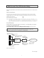
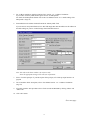
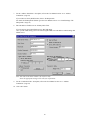
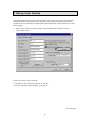
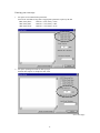
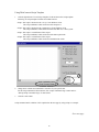
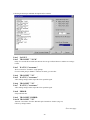
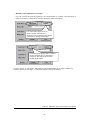
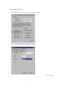
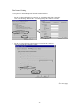
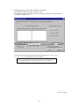
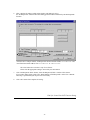
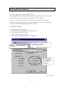
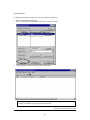
EXP Computer, Inc.
ThinConnect4
Additional functions.
NOTE: In order to make the settings mentioned in this file, It is necessary to have the following
version.
ThinConnect4 Firmware :
ThinConnect4 Setup Utility:
V2.21
V2.62
The name of the company or product name written on this document are the registered trademark or
trademark of their company.
May, 1999
Revision: 1.00 A10
EXP Computer, Inc.
1. DNS Server Settings
This Section explains DNS (Domain Name Service) server settings for ThinConnect4 when you connect
with RAS Server, Networking Dial-up, or Leased Line IP Connection.
Setting order for Name Server
TCP/IP settings
with PC
DNS settings
with TC4 DHCP
server function
DNS settings
with PC
Obtain an IP address
automatically
N/A
Specify an IP
address
Set the IP address
to TC4’s IP address
Set the IP address
to TC4’s IP
N/A
DNS settings with
TC4 Name Server
function
Set the DNS server
IP address
Set the DNS server
IP address
Note: TC4 = ThinConnect4
N/A = not applicable (leave the entry blank)
Name Server settings
1.
Click “Name Server” button at “Settings for LAN Port” window.
Go to next page
1
2.
Enter IP address of DNS server at “Primary DNS” field.
If you do not want to use name server leave this field empty.
3.
Click “OK” button.
End of 1. DNS Server Settings
2
2. Multi-Account / Proxy DNS function Settings
This section explains Multi-Account function and Proxy DNS (Domain Name Service) function and its
settings.
Multi-Account function
This function allow ThinConnect4 connect up to four different dial-up accounts connection without
changing settings on PC. Possible number of registration and translation connection will be as follows:
ISP Dial-Up IP Connection:
RAS Client Dial-Up IP Connection:
3 entry
1 entry
Note: The function of the Dial-up relation can be set only to one of the serial ports 1 or 2.
For example, if you set the serial port 1 to “ISP Dial-UP IP Connection”, you can not set up
neither “ISP Dial-UP IP Connection” nor “RAS Client Dial-UP IP Connection” on serial port 2.
Proxy DNS function
The Proxy DNS is a necessary part of “Multi-Account function”. It will change DNS server IP address
according to your selected Dial-up account.
By specifying IP Address of ThinConnect4 as DNS server address on your PC, user does not need to
change the DNS setting for the PC even if connecting ISP account has changed.
If you want to use Proxy DNS function with “ISP Dial-up IP Connection” or “RAS Client
Dial-up IP Connection” please set “IP Translation” to “IP Masquerade”.
Request for host
address from to TC4.
User queries
Request for host address
RFC 1035/1034 from
Name Server.
TC4 DNS
Queries
Modem/TA
resolver
DNS Name Server
Response with IP
address to TC4.
Response with IP
address to User.
Responses
User responses
Note: TC4 =ThinConnect4
Go to next page
3
Setting order for Proxy DNS function
TCP/IP settings
with PC
Obtain an IP address
automatically
Specify an IP
address
DNS settings
with PC
N/A
Set the IP address
of TC4
DNS settings
with TC4 DHCP
server function
DNS settings with
TC4 Dial-up IP
Connection
Set the IP address
of TC4
Set the DNS server
IP address of ISP
N/A
Set the DNS server
IP address of ISP
Note: TC4 = ThinConnect4
N/A = not applicable (leave the entry blank)
2.1 ISP Dial-Up IP connection Settings
1.
Click “Port Usage” tab on “Settings for Serial Port 1 (or 2)” window.
Choose “ISP Dial-Up IP Connection” and click “Detail Settings”. If you want to
connect to a RAS Server using the same port, choose “ISP Dial-Up IP Connection and RAS
Server IP Connection” and click “Detail Settings”.
Go to next page
4
2.
Click “ISP#1” tab.
Enter the ISP name in “Dial-up ISP Name” field
The name will be shown at “Mode/Site” pull-down selection.
3.
Enter dial-up user ID in “User Name” field.
Enter the password in “Password” field.
Note: For security reason, the password will show as “****” whatever you type in.
To verify any typing, please enter the password again in the “Confirm Password” field
4.
Enter the ISP access telephone number in “Access Number #1 to #3”.
You can enter up to three access numbers according to priority.
Note: You need to enter at least one access telephone number. The other two are back-up numbers,
in case the first number is busy. If there is any error the dialing will be stopped, except BUSY.
Go to next page
5
5.
For “Address translation” detail description refer to section “ 4.1.2. Address Translation.”
If you want to use Proxy DNS function, please choose “IP Masquerade”.
For details of IP Masquerade function refer to the User Manual section “4.1.3. Detail Settings of IP
Masquerade.” (Page 54)
6.
Enter DNS Server IP address obtained from ISP in “Primary DNS” field.
If you do not use Proxy DNS function, leave this field empty then enter the DNS server IP address on
the DNS settings on your PC or DNS settings related with DHCP Server.
Note: The value in the above window is for reference only.
Enter the appropriate setting to meet with your requirement.
7.
Select ‘Use Dial-up Scripts’ if your ISP require dial-up scripts, refer “Dial-up scripts function” on
page 16
8.
The “Translation Table” description, refer to User Manual section “4.1.2. Address Translation”.
(Page 52)
9.
If needed, repeat the same procedures above for the second and third ISP by clicking “ISP#2” and
“ISP#3” tab.
10. Click “OK” button.
Go to next page
6
11. Click right side button of “Default Outgoing Connection”.
Choose main dial-up connection account from the list by click on it.
12. Click “OK” button.
7
2.2 RAS Client Dial-Up IP Connection Settings
1.
Click “Port Usage” tab on “Settings for Serial Port 1 (or 2)” window.
Choose “RAS Client Dial-Up IP Connection” then click “Detail Settings” button.
If you want to connect to a RAS Server from the same serial port, please choose “RAS client Dial-Up
IP Connection and RAS server IP Connection” then click “Detail Settings” button.
Go to next page
8
2.
Enter the server name you wish to connect in “RAS Server Name” field.
The server name will be shown at connection site switching window.
3.
Enter the user name and password. Retype the password again in Confirm Password field.
Remark: For security reason, the password will show as **** whatever you type in.
To verify any typing, please enter the password again in the “Confirm Password” field.
4.
Enter the RAS Server's phone number in “Access Number” field.
5.
To set up “Use Call Back” feature, refer to the User Manual section “5.1.2. Call Back Function”.
(Page 74)
6.
“RAS Client IP Address” set up, refer to the User Manual section “5.1.3. IP Address
Acquiring/Assigning”. (Page 77)
Go to next page
9
7.
For the “Address Translation ” description, refer to the User Manual section “4.1.2. Address
Translation”. (Page 52)
If you wish to use Proxy DNS function, choose “IP Masquerade”.
For details of IP Masquerade function go to the User Manual section “4.1.3. Detail Settings of IP
Masquerade.” (Page 54)
8.
Enter IP address of DNS server at “Primary DNS” field.
If you do not use Proxy DNS function, leave this field empty.
Go to your PC DNS setting you need to enter designate DNS Server IP address or DNS setting with
DHCP Server.
Note: The value in the above window is for reference only.
Enter the appropriate setting to meet with your requirement.
9.
For the “Translation Table” description, refer to the User Manual section “4.1.2. Address
Translation”. (Page 52)
10. Click “OK” button.
10
2.3 DHCP Server Settings and DNS Settings for PC.
This section explains DHCP (Dynamic Host Configuration Protocol) server settings for ThinConnect4
and DNS (Domain Name Service) settings for PC in order to use “Multi Account function” and “Proxy
DNS function”.
DHCP server setting for ThinConnect4
Enter IP Address of ThinConnect4 in “Primary DNS” field at “DHCP Server” window.
Factory default setting is “192.168.0.1”.
Go to next page
11
DNS setting for PC
DNS setting for Windows 95/98
Set “Disable DNS” at “DNS Configuration” tab on “TCP/IP Properties” window.
DNS setting of Windows NT 4.0
Do not enter any DNS IP address in the “DNS Service Search Order” field on “TCP/IP Properties”
window.
Go to next page
12
Setting up DNS without the DHCP Server.
DNS setting for Windows 95/98
Set “Enable DNS” at “DNS Configuration” tab on “TCP/IP Properties” window.
Please set IP address of ThinConnect4 in “DNS Service Search Order” field.
DNS setting of Windows NT4.0
Set IP address of ThinConnect4 in “DNS Service Search Order” field on “DNS” tab of “TCP/IP
Properties” window.
13
2.4 Switching connection accounts
This section will explains how to switch between registered multiple accounts connections.
1.
Start up “TC4 Setup Utility”.
2.
If there are multiple ThinConnect4 connecting on the same LAN, click ThinConnect4 that you want
to work on.
Go to next page
14
3.
Click on “Mode/Site” pull down button.
Click on the account you wish to use from the list.
4.
The Mode/Site should show the account selected in step 3.
End of 2. Multi-Account / Proxy DNS function Settings
15
3. Dial-up Scripts function
Some ISP (Internet Service Provider) or RAS (Remote Access Service) server may require additional
information beside username and password. The dial-up script will help automate the connection by
monitor the server respond and provide appropriate keyboard input This section describes how to setup a
Dial-up Scripts.
1.
Place a check mark at “Use Dial-up Scripts” on the “ISP Dial-up IP Connection” window.
Click “Scripts” button.
There are two ways to set up a script file:
1. Entering your own scripts from scratch, go to next page.
2. Set up a script using “Script Template”, go to page 19.
Go to next page
16
Entering your own script
1.
Set up the serial communication parameters
Select from “ASCII Receiving Data” an appropriate parameter requires by the ISP.
8 Bits, Parity None:
7 Bits, Parity Odd:
7 Bits, Parity Even:
2.
Data bits = 8 bits, Parity = None
Data bits = 7 bits, Parity = Odd
Data bits = 7 bits, Parity = Even
Set up the operating time limit for Dial-up script.
Enter the time require in “Script Time Out” field.
Go to next page
17
3.
Click the edit box and enter the command and variables to send for establishing the connection.
You can choose script commands available from ThinConnect4 by click on “Script Command
Usage” button and refer to “Dial-up Script Command Usage”.
Click here to enter commands and
responds, a cursor will be shown.
Characters that you want to specify in “Data” fields please make sure to mark with double quotation
marks.
Please be careful that characters, which you specify in “Data” fields, will be case sensitive.
4.
Click “OK” button.
Go to next page
18
Using ThinConnect4 Script Template
1.
Click the right button of “Load Script Template” field and choose the Script template.
Following are Script template available from ThinConnect4.
Script1: This script is identical to the “cis.scp” from Windows 95/98.
This script establishes a PPP connection with Compuserve.
Script2: This script is identical to the “pppmenu.scp” from Windows 95/98.
This script establishes a PPP connection with a host that uses a menu system.
Script3: This script is a modification of the script2.
This script establishes a PPP connection with Chinese public ISP.
Script4: This script is a modification of the script2.
This script establishes a PPP connection with Indian ISP VSNL.
2.
Change these variables and command to customize for your specific ISP.
For the Script command of ThinConnect4, click “Script Command Usage” button and see
“Dial-up Script Command Usage” for more detail.
3.
Click the “OK” button.
Script command and its variables will be explained on the next page by using Script 2 as example.
Go to next page
19
Following are the Script command description and its variables.
Line1
Line2
PAUSE 2
TRANSMIT "^M^M"
Delay for 2 seconds first to make sure the host does not get confused when we send the two carriagereturns.
Line3
WAIT 9,3,"username:"
Wait 3 seconds for “username:” (login prompt).
If received data, jump to “Line 9”. If timeout occurred, go to next line.
Line4
Line5
TRANSMIT "^M"
WAIT 9,3, "username:"
After sending carriage-returns repeat the Line3 operation again.
Line6
Line7
TRANSMIT "^M"
WAIT 9,3, "username:"
After sending carriage-returns repeat the Line3 operation again.
Line8
ERROR
Script end with error.
Line9 TRANSMIT $USERID
Line10 TRANSMIT "^M"
Transmit “User Name” from the “ISP Dial-up IP Connection” window. (Page 16)
Follow by carriage-returns.
Go to next page
20
Line11 WAIT 13,10,"password:"
Wait 10 seconds for “password:” (password prompt)
If received data, jump to “Line 13”. If timeout occurred, go to next line.
Line12 ERROR
Script end with error.
Line13 TRANSMIT $PASSWORD
Line14 TRANSMIT "^M"
Transmit “Password” which set up at “ISP Dial-up IP Connection” window.
Line15 WAIT 17,30,"annex:"
Wait 30 second for an “annex:” (prompt).
If received data, jump to “Line 17”. If timeout occurred, go to next line.
Line16 ERROR
Script end with error.
Line17 TRANSMIT "3^M"
This sample assumes that ISP displays a menu list like this.
Feel free to add more commands if your ISP requires it.
1
: Our special GUI
2
: Establish slip connection
3
: Establish PPP connection
4
: Establish shell access
5
: Download our software
6
: Exit
annex:
Transmit “3”.
Line18 END
Script end normally.
This script assumes you only need to issue one command to continue.
Feel free to add more commands if your ISP requires it.
End of 3. Dial-Up Scripts function
21
4. Manual Connection/Disconnection button
This section explains display and operation of connect/disconnect button.
Using the “Manual Connection/Disconnection” button
The “Connect/Disconnect” button display will change according to line condition.
1.
Start up “TC4 Setup Utility”.
2.
If multiple ThinConnect4 is connected on the same LAN, click ThinConnect4, which you want to
Connect/Disconnect.
3.
The window below shows the status which “line not connect”.
If you want to connect, click “connect” button.
Go to next page
22
4.
If the connection with serial port is established, the display will change.
The window below shows the status of “line connecting”.
If you want to disconnect click “Disconnect” button.
Using “Auto-Connection/Disconnection”
If user choose the Auto-Connection/Disconnection function, (available from a Serial port “Connection
Timer tab) the “Connect” and “Disconnect” buttons display may NOT reflect the actual line condition of
a serial port.
To refresh the display of a serial port condition:
Click a ThinConnect4 from the list.
The button indicators will change according to line condition.
Click here
Button displays change according to the
actual line condition.
Go to next page
23
Manually Connect/Disconnect a serial port.
User can overwrite the serial port operation, even if button display of “Connect” and “Disconnect” is
appear to be inactive as show below, force the operation by click on the button.
Even if the button display shows as
inactive like this, when the line is
disconnected it is possible to make manual
connection by clicking on this button.
Even if the button display shows as inactive
like this, when the line is connected it is
possible to make manual disconnect by
clicking on this button.
Or click “connect” or “Disconnect” button after you made button display in accordance with the line
condition. See the previous page “ To refresh the display a serial port condition”
End of 4. Manual Connection/Disconnection button
24
5. SNTP Client/Server Settings
This section explains settings for SNTP/NTP (Simple Network Time Protocol/Network Time Protocol)
client and SNTP server function in the ThinConnect4. The ThinConnect4 implement the SNTP
client/Server as the following:
SNTP/NTP Client function
Using SNTP/NTP server on Internet (or LAN) to make time adjustment for ThinConnect4.
SNTP Server function
ThinConnect4 will inform time status to SNTP client (PC). Required a SNTP/NTP client program
(See Note)
Using SNTP/NTP server
on the Internet to adjust
ThinConnect4’ s time.
SNTP Server
NTP Server
Modem/TA
Internet
ThinConnect4
Using the ThinConnect4
as SNTP /NTP server to
inform time to PC client.
Note: There are SNTP/NTP clients programs for PC available from various sources on the Internet. (Go to any search
engine’s WEB page and search for SNTP or NTP)
PC’s time setting when the SNTP/NTP is disabled.
At the following event, time status of a PC will be set to ThinConnect4 time.
• At the time “ThinConnect4 setup utility” startup.
• Click “Search” button on startup window of “ThinConnect4 Setup Utility”.
• Click “update” or “cancel” button on the “General settings” window.
PC’s time setting when the SNTP/NTP is enabled.
ThinConnect4 will get time status from SNTP/NTP server and update the ThinConnect4 internal time.
The ThinConnect4 will update time status at the following cases.
• When the line is connected.
• When “Interval time” which previously set on this function become in effect while
line connected.
Go to next page
25
•
In order to SNTP server function become effective, it is necessary to get time status
more than once from other SNTP/NTP server.
•
SNTP/NTP client function will not initiate the get time status from server if the line is not
connected. (Automatic connection by client function is not possible).
The getting time status from SNTP/NTP server will become effective only when the line
is already connected.
•
To get time status from SNTP/NTP server is not consider as a communication.
•
PC time will take effect, until ThinConnect4 get time status from SNTP/NTP server..
<Example: Dial-up IP Connection>
Update by setting “Use SNTP server
function”.
Get time status from PC:
Effective
Get time status from
a SNTP/NTP server
Connect to Internet.
See Note:1, 2
Get time status from a
SNTP/NTP server
“Interval time” due.
Get time status from PC:
Ineffective
Disconnect the line.
Connect to Internet.
“Interval time” due.
Get time status from a
SNTP/NTP server
Note:
1.
2.
If ThinConnect4 fail to get time status from other SNTP/NTP server, then time status from PC
will be used.
The ThinConnect4 SNTP server function will becomes effective as soon as the ThinConnect4
successfully get time status from a SNTP/NTP server.
Go to next page
26
Setting up the SNTP Server
1.
From “Settings for LAN port” window, click “SNTP Server” button.
2.
Place a check mark at the box “Use SNTP server function”.
If you do not wish to use this function leave the box empty.
Go to next page
27
3.
Enter SNTP Server name or IP Address at “SNTP Server” field.
(See next page for North America server list)
Enter “Interval time” (in minute) which ThinConnect4 will get time status update from SNTP Server
at “Interval“ field.
4.
Click right pull-down “Time Zone” button.
Select Time zone from the list where you are located.
Time zone of Japan (GMT+09:00) has been set as factory default.
If you do not know which time zone you are located,
Go to “My Computer” choose “Control Panel, click “Date/Time” then “Time zone” tab.
5.
Click “OK” button.
Go to next page
28
Setting for PC client program
Enter ThinConnect4 IP address or nicknames on Server setting Items with SNTP Client software
for PC.
If you want to make settings by nicknames add a “.” (Period) after the ThinConnect4‘s nicknames in
the SNTP client software server settings.
< Example> ThinConnect4 nickname:
Server settings of SNTP Client software:
“SAM”
“SAM.” <-Add period at the end.
North America SNTP server list.
bitsy.mit.edu
clock.isc.org
ncar.ucar.edu
ntp.css.gov
ntp2.usno.navy.mil
tick.usask.ca
timelord.cs.uregina.ca
tick.usno.navy.mil
End of 5. SNTP Client/Server Settings
29
6. NAT and IP Masquerade Function Setting
The NAT (Network Address Translation) and IP Masquerade functions are available from the following
connection mode.
•
•
•
•
ISP Networking Dial-Up IP Connection
Networking Dial-Up IP Connection
ISP Leased Line IP Connection
Leased Line IP Connection
By utilizing the NAT and IP Masquerade function, ThinConnect4 will be able to translate global IP
address into private network IP address.
IP Translation Method
Translate from one global IP Address
A good example of this type of translation is when ThinConnect4 connecting to an ISP. Once connected,
ISP will assign only. The IP Masquerade will translate one global IP address (xxx.xxx.xxx.1) to multiple
private networks (192.168.0.1 to 192.168.0.254)
IP
= IP Address
SNM = Subnet Mask
PC1
IP: 192.168.0.2
ThinConnect4
LAN settings
IP: 192.168.0.1
SNM: 255.255.255.0
PC2
IP: 192.168.0.3
PC3
IP: 192.168.0.4
Modem/
TA
Internet
Global IP Address to
translate.
xxx.xxx.xxx.1
PC4
IP: 192.168.0.5
Go to next page
30
Translate from Multiple global IP Address
In this example the ISP allocate a block of global IP address to ThinConnect4.
NAT will translate global IP address to private IP address base on one to one basis.
The IP Masquerade will translate final set global IP address to multiple private IP address.
Example:
• Global IP address from ISP:
111.111.111.128
• Subnet mask from ISP:
255.255.255.248
Number of global IP address of the above network address is 8.
(From “111.111.111.128” to “111.111.111.135”)
In this case “111.111.111.128” will be used as Network Address and “111.111.111.135” will be used as
broadcast address. These two IP addresses are reserved and can not allocate to PC and Router.
There for the usable global IP Address is 6 from “111.111.111.129” to “111.111.111.134”.
Enter the “Use IP Address Translation” as: (See ThinConnect4 setting next page)
“Start IP Address“: 111.111.111.129
“Number of Address”: 6
PC 1
IP: 192.168.0.2
ThinConnect4
PC 2
IP: 192.168.0.3
LAN settings
IP: 192.168.0.1
SNM: 255.255.255.0
PC 3
IP: 192.168.0.4
Global IP Address to
translate from
111.111.111.129
to
111.111.111.134
(6)
PC 4
IP: 192.168.0.5
PC 5
IP: 192.168.0.6
PC 253
IP: 192.168.0.254
Global IP Address
111.111.111.129
111.111.111.130
111.111.111.131
111.111.111.132
111.111.111.133
111.111.111.134
Internet
Modem/
TA
HUB
IP
= IP Address
SNM = Subnet Mask
Private IP Address
192.168.0.1
192.168.0.2
192.168.0.3
192.168.0.4
192.168.0.5
192.168.0.6 to 192.168.0.254
31
Address Translation
NAT
NAT
NAT
NAT
NAT
IP Masquerade
ThinConnect4 Setting
To setup the NAT and IP Masquerade follow the instructions below.
1. For the “ISP Networking Dial-Up connection” or “Networking Dial-Up IP Connection”.
Click “Static Routing” button on the “Networking Dial-Up IP Connection” window.
2. For the “ISP Leased Line IP Connection” and “Leased Line IP Connection”.
Open “Leased Line IP Connection” window.
Go to next page
32
3.
The Routing for Serial Port window will be shown.
4.
Place a check mark on “Use IP Address Translation”.
If you do not use this function leave the entry blank. (There is no Address Translation taking place).
Go to next page
33
5.
Setting the global IP Address and it’s number to be translated.
Enter starting IP address into “Start IP Address“ field.
Enter number of IP addresses which you want to translated in sequence of “Start IP Address”
at “Number of Address” field.
The above window examples shows the global IP Address from “111.111.111.1” to
“111.111.111.6” to be translated into Private IP Address.
The value in the above window is only for a reference.
Please enter the appropriate setting to meet with your environment.
Go to next page
34
6.
After complete all settings on this setting window (OK button is active),
the “IP Masquerade” field will show the starting global IP address translated by the IP Masquerade
function.
.
From the above example window, IP Masquerade function translate address “111.111.111.6” and
NAT function translate address from “111.111.111.1” to “111.111.111.5”.
The value in the above window is only for a reference.
Please enter the appropriate setting to meet with your environment.
7.
Click “IP Masquerade Table” button, “Static IP Masquerade Table” window will be shown.
If you want to make setting, please refer “Detail Settings of IP Masquerade” on the User’s Manual.
This setup is optional that you can proceed it if necessary.
8.
Click “OK” button after completes all setting.
End of 6. Leased Line NAT Function Setting
35
7. Change or Add Firewall items
This section explains the procedure to change or add Firewall items available in this version.
Factory default
The following Firewall function is set up at the factory.
l
l
Interdict automatic line connection by ICMP.
Interdict automatic line connection by NetBIOS on TCP/IP Services.
(Interdict automatic line connection by Windows startup and finish)
l Interdict automatic line connection beside TCP connection (SYN) flag.
(Interdict automatic line connection by the end of application)
l Interdict automatic line connection by BOOTP, TFTP.
l Interdict automatic line connection by Apple Talk.
l Shut out to supply NetBIOS on TCP/IP Services to ThinConnect4 application (Proxy DNS
function, SNTP server function, etc).
(Interdict automatic line connection if ThinConnect4 application start)
The above 6 items is applicable to use on the same LAN.
Be careful, when you change or delete the above control default value. It may cause ThinConnect4 to
behave erratically such as unwilling dial-up, or not able to make connection during dial-up.
If the problem occur, EXP recommend setting IP filter to the default value.
Click “Return to Default” button will set “Firewall - IP Filter Table” to default.
Go to next page
36
Change the Factory default items
Entry No. 2 (partial change)
< Interdict automatic connection of line by NetBIOS on TCP/IP >
ACTION
NC:CUT
(no change)
INport
anyport
(no change)
OUTport
SIO:any
(before change “anyport”)
IP/Mask : Src.
No setting
(no change)
IP/Mask : Dst.
No setting
(no change)
IP/Mask : AND/OR
No setting
(no change)
Port No : Src.
netbios-ns/netbios-ssn
(no change)
Port No : Dst.
netbios-ns/netbios-ssn
(no change)
Port No : AND/OR
OR
(no change)
Protocol :
any
(no change)
Entry No. 6 (Newly added)
< Shut out to supply NetBIOS on TCP/IP Services to a ThinConnect4 application >
ACTION
CUT
IN (INport)
anyport
OUT (OUTport)
OWNapp
IP/Mask : Src.
No setting
IP/Mask : Dst.
No setting
IP/Mask : AND/OR
No setting
Port No : Src.
netbios-ns/netbios-ssn
Port No : Dst.
netbios-ns/netbios-ssn
Port No : AND/OR
OR
Protocol :
UDP
Go to next page
37
Newly added setting Items
“OWNapp” will be added for port selection in “IN (INport)” and “OUT (OUTport)”.
OWNapp: These are ThinConnect4 application. (Proxy DNS function, SNTP Client/server function,
E-mail share function, etc)
Reference samples:
“IN” = “LANport” “OUT” = “OWNapp” :
-> Objected IP frame from LAN port to ThinConnect4 application. ???????????
“IN” = “OWNapp” “OUT” = “SIO:P1” :
-> Objected IP frame from ThinConnect4 application to serial port 1. ??????????
For details “Firewall – IP Filter Table” please refer to the Manual book attached to the product on the
article “7.1 Firewall – IP Filter Table Settings”.
End of 7. Changed/Added items of Firewall Function
38
8. Syslog Monitor function
This section explains detail of Syslog Monitor function.
The Syslog Monitor function displays and log system activity information of the ThinConnect4.
The detail information such as of connection/disconnection will be available.
In order to use Syslog Monitor function, it is necessary to set up the Syslog function first.
For details of “Syslog settings” please refer to the User Manual on section “7.3 Syslog settings”.
A simple Syslog function setting will be explained as follows.
Syslog function settings
1.
2.
3.
4.
5.
Start “ThinConnect4 Setup utility”.
Select ThinConnect4 to setup and click “Settings” button.
Click “Settings” button in “LAN Port”.
Click “Syslog” button in “Advanced”.
Setup the items mentioned below and click “OK” button.
Enter check mark at “Enable Syslog
Function”.
Enter IP address of PC to receive Syslog
or “255,255,255,255” (broadcast)
in “Host IP Address” fields.
Place check marks on
“LOG_WARNING”,
“LOG_NOTICE” and
“LOG_INFO” as a
minimum log.
Go to next page
39
Syslog Monitor
To display the information logged by the Syslog, follow the step below.
1.
Start “ThinConnect4 Setup utility”.
Select a ThinConnect4 from the list and click the “Monitor” button.
2.
“Syslog Monitor” will start up and window will be open.
When other syslog program is on, it will be possible that syslog Information might not shown.
Do not work with other syslog program at the same time.
End of 8. Syslog Monitor function
40