1
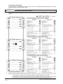
INSTRUCTION MANUAL
Light Curtain
Type 4
SF4B Series
SUNX Limited MJE-SF4B No.6084-00
-1-
(MEMO)
SUNX Limited MJE-SF4B No.6084-00
-2-
Thank you for purchasing SUNX’s Light Curtain, SF4B series (hereinafter called ‘this
device’).
Please read this instruction manual carefully and thoroughly for the correct and optimum use
of this product.
Kindly keep this manual in a convenient place for quick reference.
This device is a light curtain for protecting a person from dangerous parts of a machine which
can cause injury or accident.
This manual has been written for the following personnel who have undergone suitable
training and have knowledge of light curtains, as well as, safety systems and standards.
・ who are responsible for the introduction of this device
・ who design the system using this device
・ who install and connect this device
・ who manage and operate a plant using this device
Note
1) All the contents of this instruction manual are the copyright of the publishers, and may
not be reproduced (even extracts) in any form by any electronic or mechanical means
(including photocopying, recording, or information storage and retrieval) without
permission in writing from the publisher.
2) The contents of this instruction manual may be changed without prior notice for further
improvement of the product.
3) Though we have carefully drawn up the contents of this instruction manual, if there are
any aspects that are not clear, or any error that you may notice, please contact our local
SUNX office of the nearest distributor.
SUNX Limited MJE-SF4B No.6084-00
-3-
Contents
Introduction ・・・・・・・・・・・・・・・・・・・・・・・・・・・・・・・・・・・・・・・・・・ 6
Attention Marks ・・・・・・・・・・・・・・・・・・・・・・・・・・・・・・・・・・・・・・・・・・・
Safety Precautions ・・・・・・・・・・・・・・・・・・・・・・・・・・・・・・・・・・・・・・・・
Applicable Standards ・・・・・・・・・・・・・・・・・・・・・・・・・・・・・・・・・・・・・・
Confirmation of Packed Contents ・・・・・・・・・・・・・・・・・・・・・・・・・・・・
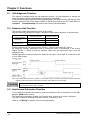
Chapter 1
1-1
1-2
1-3
6
6
9
9
Before Using This Device ・・・・・・・・・・・・・・・・・・ 10
Features ・・・・・・・・・・・・・・・・・・・・・・・・・・・・・・・・・・・・・・・・・・・ 10
Part Description ・・・・・・・・・・・・・・・・・・・・・・・・・・・・・・・・・・・・・ 10
Protection Area ・・・・・・・・・・・・・・・・・・・・・・・・・・・・・・・・・・・・・ 12
1-3-1
1-3-2
1-3-3
1-3-4
Sensing Area ・・・・・・・・・・・・・・・・・・・・・・・・・・・・・・・・・・・・・・・・・ 12
Safety Distance ・・・・・・・・・・・・・・・・・・・・・・・・・・・・・・・・・・・・・・・ 13
Influence of Reflective Surfaces ・・・・・・・・・・・・・・・・・・・・・・・・・ 17
Sensor Placement・・・・・・・・・・・・・・・・・・・・・・・・・・・・・・・・・・・・・ 18
1-4
Mounting ・・・・・・・・・・・・・・・・・・・・・・・・・・・・・・・・・・・・・・・・・・・ 19
1-5
Wiring ・・・・・・・・・・・・・・・・・・・・・・・・・・・・・・・・・・・・・・・・・・・・・・ 26
1-4-1 Mounting of the Mounting Bracket ・・・・・・・・・・・・・・・・・・・・・・・ 19
1-4-2 Mounting of the Bottom Cap Cable (Optional) ・・・・・・・・・・・・ 23
1-4-3 Extension and Dismantling of Sensor (Series Connection) ・・ 24
Power Supply Unit ・・・・・・・・・・・・・・・・・・・・・・・・・・・・・・・・・・・・ 26
I/O Circuit Diagrams ・・・・・・・・・・・・・・・・・・・・・・・・・・・・・・・・・・・ 27
Wiring・Connecting Procedure ・・・・・・・・・・・・・・・・・・・・・・・・・ 29
Wiring for Manual Reset (Interlock is Valid) ・・・・・・・・・・・・・・・ 31
Wiring for Auto-reset (Interlock is Invalid) ・・・・・・・・・・・・・・・・・ 33
Wiring Configuration for Invalid External
Device Monitor Function ・・・・・・・・・・・・・・・・・・・・・・・・・・・・・・・ 34
1-5-7 Connection Configuration When Using Muting Function ・・・・・ 34
1-5-1
1-5-2
1-5-3
1-5-4
1-5-5
1-5-6
1-6
Adjustment ・・・・・・・・・・・・・・・・・・・・・・・・・・・・・・・・・・・・・・・・・ 35
1-6-1 Beam-axis Alignment・・・・・・・・・・・・・・・・・・・・・・・・・・・・・・・・・・ 35
1-6-2 Operation Test ・・・・・・・・・・・・・・・・・・・・・・・・・・・・・・・・・・・・・・・ 37
1-6-3 Operation ・・・・・・・・・・・・・・・・・・・・・・・・・・・・・・・・・・・・・・・・・・・・ 38
Chapter 2 Functions ・・・・・・・・・・・・・・・・・・・・・・・・・・・・・・・・ 44
2-1
2-2
2-3
2-4
2-5
2-6
2-7
2-8
2-9
Self-diagnosis Function ・・・・・・・・・・・・・・・・・・・・・・・・・・・・・・
Emission Halt Function ・・・・・・・・・・・・・・・・・・・・・・・・・・・・・・・
Interference Prevention Function ・・・・・・・・・・・・・・・・・・・・・・
Auxiliary Output (Non-safety Output) ・・・・・・・・・・・・・・・・・・・
Interlock Function ・・・・・・・・・・・・・・・・・・・・・・・・・・・・・・・・・・・
External Device Monitor Function ・・・・・・・・・・・・・・・・・・・・・・
Muting Function ・・・・・・・・・・・・・・・・・・・・・・・・・・・・・・・・・・・・・
Override Function ・・・・・・・・・・・・・・・・・・・・・・・・・・・・・・・・・・・
Functions Using Handy Controller (SFB-HC) (Available Soon) ・
44
44
44
45
45
46
47
50
52
SUNX Limited MJE-SF4B No.6084-00
-4-
Maintenance ・・・・・・・・・・・・・・・・・・・・・・・・・・・・・・・・・・・ 54
Daily Inspection ・・・・・・・・・・・・・・・・・・・・・・・・・・・・・・・・・・・・・・ 54
Periodic Inspection (Every Six Months) ・・・・・・・・・・・・・・・・・ 55
Inspection after Maintenance ・・・・・・・・・・・・・・・・・・・・・・・・・・ 55
Chapter 3
3-1
3-2
3-3
Chapter 4
4-1
4-2
Troubleshooting・・・・・・・・・・・・・・・・・・・・・・・・・・・ 56
Troubleshooting of Emitter ・・・・・・・・・・・・・・・・・・・・・・・・・・・・ 56
Troubleshooting of Receiver ・・・・・・・・・・・・・・・・・・・・・・・・・・・ 57
Chapter 5 Specifications・Dimensions ・・・・・・・・・・・・・・・・ 58
5-1
5-2
5-3
Specifications・・・・・・・・・・・・・・・・・・・・・・・・・・・・・・・・・・・・・・・・ 58
Options ・・・・・・・・・・・・・・・・・・・・・・・・・・・・・・・・・・・・・・・・・・・・・ 62
Dimensions ・・・・・・・・・・・・・・・・・・・・・・・・・・・・・・・・・・・・・・・・・ 66
5-3-1
5-3-2
5-3-3
5-3-4
5-3-5
Rear Mounting with Standard Mounting Bracket (MS-SFB-1) ・
Side Mounting with Standard Mounting Bracket (MS-SFB-1) ・・
Rear Mounting with Dead Spaceless Bracket (MS-SFB-3) ・・・
Side Mounting with Dead Spaceless Bracket (MS-SFB-3) ・・・・
Mounting Brackets ・・・・・・・・・・・・・・・・・・・・・・・・・・・・・・・・・・・・
66
67
68
69
70
Chapter 6 Others ・・・・・・・・・・・・・・・・・・・・・・・・・・・・・・・・・・・ 72
6-1
Glossary ・・・・・・・・・・・・・・・・・・・・・・・・・・・・・・・・・・・・・・・・・・・・ 72
SUNX Limited MJE-SF4B No.6084-00
-5-
Introduction
Attention Marks
This instruction manual employs the following attentions marks
,
depending on the degree of the danger to call operator’s attention to each particular action.
Read the following explanation of these marks thoroughly and observe these notices without
fail.
If you ignore the advice with this mark, death or serious injury could result.
If you ignore the advice with this mark, injury or material damage could
result.
<Reference>
It gives useful information for better use of this device.
Safety Precautions
■ Use this device as per its specifications. Do not modify this device since its functions and
capabilities may not be maintained and it may malfunction.
■ Use of this device under the following conditions or environment is not presupposed.
Please consult us if there is no other choice but to use this device in such an environment.
1) Operating this device under conditions and environment not described in this manual.
2) Using this device in the following fields: nuclear power control, railroad, aircraft,
automobiles, combustion facilities, medical systems, aerospace development, etc.
■ When this device is to be used for enforcing protection of a person from any danger
occurring around an operating machine, the user should satisfy the regulations
established by national or regional security committees (Occupational Safety and Health
Administration: OSHA, the European Standardization Committee, etc.). Contact the
relative organization(s) for details.
■ In case of applying this device to particular equipment, follow the safety regulations in
regard to appropriate usage, mounting (installation), operation and maintenance. The
users including the installation operator are responsible for the introduction of this device.
■ Use this device by installing suitable protection equipment as a countermeasure for
failure, damage, or malfunction of this device.
■ Before using this device, check whether the device performs properly with the functions
and capabilities as per the design specifications.
■ In case of disposal, dispose this device as industrial waste.
◎ Machine designer, installer, employer and operator
・ The machine designer, installer, employer and operator are solely responsible to
ensure that all applicable legal requirements relating to the installation and the use in
any application are satisfied and all instructions for installation and maintenance
contained in the instruction manual are followed.
・ Whether this product functions as intended to and systems including this product
comply with safety regulations depends on the appropriateness of the application,
installation, maintenance and operation. The machine designer, installer, employer
and operator are solely responsible for these items.
◎ Engineer
・ The engineer would be a person who is appropriately educated, has widespread
knowledge and experience, and can solve various problems which may arise during
work, such as a machine designer, or a person in charge of installation or operation
etc.
SUNX Limited MJE-SF4B No.6084-00
-6-
◎ Operator
・ The operator should read this instruction manual thoroughly, understand its contents,
and perform operations following the procedures described in this manual for the
correct operation of this device.
・ In case this device does not perform properly, the operator should report this to the
person in charge and stop the machine operation immediately. The machine must
not be operated until correct performance of this device has been confirmed.
◎ Environment
・ Do not use a mobile phone or a radio phone near this device.
・ Install the sensor by considering the effect of nearby reflective surfaces, and
take countermeasures, such as painting, masking, roughening, or changing the
material of the reflective surfaces, etc. Failure to do so may cause the sensor not to
detect, resulting in death or serious body injury.
・ Do not install this device in the following environments.
1) Areas exposed to intense interference (extraneous) light such as direct sunlight
2) Areas with high humidity where condensation is likely to occur
3) Areas exposed to corrosive or explosive gases
4) Areas exposed to vibration or shock of levels higher than that specified
5) Areas exposed to contact with water
6) Areas exposed to too much steam or dust
7) Areas where the beam-receiving part of this device is directly exposed to light
from high-frequency fluorescent lamp (inverter type) or rapid starter fluorescent
lamp.
◎ Installation
・ Always keep the correctly calculated safety distance between this device and the
dangerous parts of the machine.
・ Install extra protection structure around the machine so that the operator must pass
through the sensing area of this device to reach the dangerous parts of the machine.
・ Install this device such that some part of the operator’s body always remains in the
sensing area when operator is done with the dangerous parts of the machine.
・ Do not install this device at a location where it can be affected by wall reflection.
・ When installing multiple sets of this device, connect the sets and, if necessary, install
some barriers such that mutual interference does not occur.
・ Do not use this device in a reflective configuration.
・ The corresponding emitter and receiver must have the same serial No. and be
correctly oriented.
◎ Equipment in which this device is installed
・ When this device is used in the ‘PSDI Mode’, an appropriate control circuit must be
configured between this device and the machinery. For details, be sure to refer to the
standards or regulations applicable in each region or country.
・ In Japan, do not use this device as safety equipment for a press machine.
・ Do not install this device with a machine whose operation cannot be stopped immediately
in the middle of an operation cycle by an emergency stop equipment.
・ This device starts the performance after 2 seconds from the power ON. Have the
control system started to function with this timing.
SUNX Limited MJE-SF4B No.6084-00
-7-
◎ Wiring
・ Be sure to carry out the wiring in the power supply off condition.
・ All electrical wiring should conform to the regional electrical regulations and laws.
The wiring should be done by engineer(s) having the special electrical knowledge.
・ Do not run the sensor cable together with high-voltage lines or power lines or put
them together in the same raceway.
・ In case of extending the cable of the emitter or the receiver, each can be extended up
to 50m by using the exclusive cable. Furthermore, if the cable is extended in the
state that the sensor is in series connection, or the muting lamp is used, the total
extendable length of the cable depends on the number of the sensors in series
connection. For details, refer to ‘1-5-3 Wiring・Connecting procedure’.
・ Do not control the device only at one control output (OSSD 1, OSSD 2).
◎ Maintenance
・ When replacement parts are required, always use only genuine supplied replacement
parts. If substitute parts from another manufacturer are used, the sensor may
not come to detect, result in death or serious body injury.
・ The periodical inspection of this device must be performed by an engineer having the
special knowledge.
・ After maintenance or adjustment, and before starting operation, test this evice
following the procedure specified in ‘Chapter 3 Maintenance’.
・ Clean this device with a clean cloth. Do not use any volatile chemical.
◎ Others
・ Never modify this device. Modification may cause the sensor not to detect, resulting
in death or serious body injury.
・ Do not use this device to detect objects flying over the sensing area.
・ Do not use this device to detect transparent objects, translucent objects or objects
smaller than the specified minimum sensing objects.
SUNX Limited MJE-SF4B No.6084-00
-8-
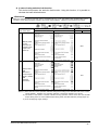
Applicable Standards
This device corresponds to the following standards.
Corresponding Territory
Japan
Europe (EU)
United States of America
Canada
Standard No.
JIS B 9704-1/2 (Type 4)
JIS B 9705-1 (ISO 13849-1)
(Category 4)
EN 61496-1 (Type 4)
IEC 61496-1/2 (Type 4)
EN 954-1 (Category 4)
IEC 61496-1/2 (Type 4)
UL 61496-1/2 (Type 4)
UL 1998
OSHA 1910.212
OSHA 1910.217(C)
ANSI B11.1 to B11.19
ANSI/RIA 15.06
Authorizing
Organization
-
DEMKO
UL
-
<Reference>
Since JIS, OSHA and ANSI are not the authorizing organization for this device, the conformity to there
standards has been evaluated by ourselves.
mark has the same validity as the CSA mark.
In Canada, the
This device conforms to the EMC directive and the Machinery directive. The
body indicates that this product conforms to the EMC directive.
mark on the sensor main
・ In Japan, never use this device as a safety equipment for any press machine or shearing
machine.
・ When this device is used in a place other than the places shown in the table above, be sure
to confirm the standards or regulations applicable in each region or country before use.
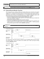
Confirmation of Packed Contents
□Sensor: Emitter, Receiver
□Test Rod
each 1pc.
1 pc.
For SF4B-F□: SFB-TR14 (φ14×220mm), For SF4B-H□: SFB-TR25 (φ25×220mm)
□Intermediate Supporting Bracket (MS-SFB-2)
0 to 3 sets
Note: The intermediate support bracket (MS-SBF-2) is enclosed with the following products. The quantity
differs depending on the product as shown below:
1 set: SF4B-F□・・・Sensor with 79 to 111 beam channels
SF4B-H□・・・Sensor with 40 to 56 beam channels
SF4B-A□・・・Sensor with 20 to 28 beam channels
2 sets: SF4B-F127, SF4B-H□・・・Sensor with 64 to 80 beam channels
SF4B-A□・・・Sensor with 32 to 40 beam channels
3 sets: SF4B-H□・・・Sensor with 88 to 96 beam channels
SF4B-A□・・・Sensor with 44 to 48 beam channels
□Instruction Manual (this manual)
1 pc.
SUNX Limited MJE-SF4B No.6084-00
-9-
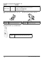
Chapter 1 Before Using This Device
1-1 Features
This device is the light curtain with the following features.
・ No special controller is required.
・ The control output (OSSD 1, OSSD 2) is PNP/NPN output switching type.
・ Beam-axis alignment indicators which make beam-axis alignment easy are incorporated.
・ Each function setting is available by using the handy controller (SFB-HC) (available
soon). Refer to ‘2-9 Function Using Handy Controller (SFB-HC) (Available Soon)’
for details.
・ Refer to ‘5-2 Options’ for details of options.
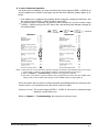
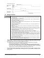
1-2 Part Description
Emitter
: It emits light to the receiver facing it. Furthermore, the status of the emitter and the
receiver is indicated on its display section.
Receiver : It receives light from the emitter facing it. Simultaneously, it turns ON the control output
(OSSD 1, OSSD 2) when the all beam channels receive light from emitter, and it turns
OFF the control output (OSSD1, OSSD2) when one or more beam channels are blocked
light [except when the muting function (Note 1) and blanking function (Note 2) are used].
Besides, the receiver displays its status on the display section.
Notes: 1) In case of using the muting function, the following items, 12-core bottom cap cable (SFB-CB05-MU,
SFB-CCB□-MU) (optional), muting sensor and muting lamp are required. Please purchase 12-core bottom
cap cable, muting sensor, and muting lamp separately.
2) The blanking function is set by using the handy controller (SFB-HC) (optional). Please purchase the handy
controller separately. Besides, in case of using the 12-core cable, the handy-controller connection cable
(SFB-CCJ02-HC) (optional) is also required. Please purchase it separately as well.
SUNX Limited MJE-SF4B No.6084-00
- 10 -
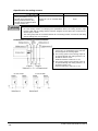
Beam channel
Standard
mounting bracket
(optional)
Dead spaceless
bracket (optional)
: The light emitting elements of the emitter and the light receiving elements
of the receiver are placed at the following intervals, 10mm (SF4B-F□),
20mm (SF4B-H□), and 40mm (SF4B-A□).
: This bracket is to be used for mounting the emitter / receiver. It enables to
adjust the horizontal mounting angle using the standard mounting bracket.
: This dead spaceless bracket is used for mounting both emitter and receiver.
This bracket is useful for mounting the sensor to the limited mounting space.
Intermediate
: This bracket is to be used for mounting the sensor having 79 beam channels or
more for SF4B-F□, 40 beam channels or more for SF4B-H□, 20 beam
supporting bracket
channels or more for SF4B-A□ in places where vibration is intense. If the
(optional)
intermediate supporting bracket is not used for mounting, the condition for type4
is not satisfied. Be sure to use the intermediate supporting bracket for mounting.
Display section:
Notes: 1) Since the color of the operation indicator changes according to the ON/OFF status of the control output
(OSSD 1, OSSD 2), the operation indicator is marked as ‘OSSD’ on the sensor.
2) The threshold where the control output (OSSD 1, OSSD 2) changes from OFF to ON is applied as ‘100%
incident beam intensity’.
3) The status ‘when light is blocked’ refers to the status that the some obstacle is existed in the sensing area.
4) The blanking function is set by using the handy controller (SFB-HC) (optional). Please purchase the handy
controller separately. Besides, in case of using the 12-core cable, the handy controller connection cable
(SFB-CCJ02-HC) (optional) is also required. Please purchase it separately as well.
5) The description given in [ ] is marked on the sensor.
SUNX Limited MJE-SF4B No.6084-00
- 11 -
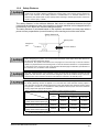
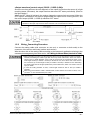
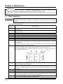
1-3 Protection Area
1-3-1
Sensing Area
・ Be sure to install protection structure around the machine so that the operator must pass
through the sensing area of this device to reach the dangerous parts of the machine.
Furthermore, ensure that some part of the operator’s body always remains in the sensing
area when operation is done with the dangerous parts of the machine. Failure to do so can
result in serious injury or death.
・ Do not use any reflection type or recursive reflection type arrangement.
・ When connecting the sensor, use the correct combination of emitter and receiver (same
beam pitch and number of beam channels) and match their top-bottom orientation.
Combining different types of emitter and receiver could produce a non-sensing area, which
may result in serious injury or death.
・ Furthermore, facing several receivers towards one emitter, or vice versa, could produce a
non-sensing area or cause mutual interference, which may result in serious injury or death.
The sensing area is the zone formed by the sensing height of the sensor and the sensing
range between the emitter and the receiver. The sensing height is determined by the number
of beam channels. Furthermore, the sensing range can be 0.3 to 9m for SF4B-H□ (12 to 64
beam channels) and SF4B-A□ (6 to 32 beam channels), 0.3 to 7m for SF4B-F□ and
SF4B-H□ (72 to 96 beam channels) and SF4B-A□ (36 to 48 beam channels). Take care
that the sensing range becomes short after mounting either protection cover (FC-SFBH-□)
(optional) or slit (OS-SFBH-□) (optional). Take care that if the sensing range is less than
0.3m, malfunction may occur due to the optical structure.
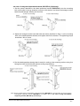
<Example of Correct Installation>
Dangerous
part
Sensing
area
Protective structure
Dangerous
part
Sensing area
<Example of Incorrect Installation>
Sensing
area
Dangerous
part
Sensing area
Dangerous
part
SUNX Limited MJE-SF4B No.6084-00
- 12 -
1-3-2
Safety Distance
Calculate the safety distance correctly, and always maintain the distance which is equal to or
greater than the safety distance, between the sensing area of this device and the dangerous
parts of the machine. If the safety distance is miscalculated or if sufficient distance is not
maintained, the machine will not stop quickly before reaching to the dangerous parts, which can
result in serious injury or death.
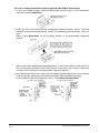
The safety distance is the minimum distance that must be maintained between the light
curtain and the dangerous parts of the machine so that the machine can be stopped before a
human body or an object can reach the dangerous parts.
The safety distance is calculated based on the equation described in the next page when a
person moves perpendicular (normal intrusion) to the sensing area of the area sensor.
Safety distance S
Sensing area
Dangerous
part
Intrusion direction
Before designing the system, refer to the relevant standards of the region where this device is to
be used, and then install this device.
Furthermore, the equation described in the next pages is to be used only in case the intrusion
direction is perpendicular to the sensing area. In case the intrusion direction is not perpendicular
to the sensing area, be sure to refer to the relevant standard (regional standard, specification of
the machine, etc.) for details of the calculation.
The max. response time of the machine is from the point that the machine receives the halt
signal from this device to the point that the dangerous part of the machine stops. The max.
response time of the machine should be timed with the machine to be actually used.
The applicable pitch of the beam channel for this device varies depending on the case whether
the floating blanking function is applied or not, and the size of the minimum sensing object is
also changed. The equation differs depending on the case whether the minimum sensing object
is larger than φ40mm or not. Calculate the safety distance with the proper size of the minimum
sensing object and appropriate equation.
<Size of minimum sensing object when applying floating blanking function>
Floating blanking function
Setting (Note)
Invalid
1 beam
2 beam
3 beam
channel
channels
channels
SF4B-F□
φ14mm
φ24mm
φ34mm
φ44mm
(10mm beam channel pitch type)
SF4B-H□
φ25mm
φ45mm
φ65mm
φ85mm
(20mm beam channel pitch type)
SF4B-A□
φ45mm
φ85mm
φ125mm
φ165mm
(40mm beam channel pitch type)
Note: Refer to ‘2-9 Functions Using Handy Controller (SFB-HC) (Available Soon)’ for details
of the floating blanking function.
SUNX Limited MJE-SF4B No.6084-00
- 13 -
[For use in Europe (EU) (as EN 999)] (Also applicable to ISO 13855)
(For intrusion direction perpendicular to the sensing area)
<In case that the minimum sensing object isφ 40mm or less>
S=K×T+C
・ Equation ①
S: Safety distance (mm)
Minimum required distance between the sensing area surface and the dangerous parts of the
machine
K: Intrusion velocity of operator’s body or object (mm/s)
Taken as 2,000 (mm/s) for calculation
T: Response time of total equipment (s)
T=Tm+TSF4B
Tm: Maximum halting time of device (s)
TSF4B: Response time of this device (s)
C: Additional distance calculated from the size of the minimum sensing object of the
sensor (mm)
However, the value of C cannot be 0 or less.
C=8×(d-14)
d: Minimum sensing object diameter (mm)
<Reference>
・ For calculating the safety distance S, there are the following five cases.
First calculate by substituting the value K=2,000 (mm/s) in the equation above. Then, classify the obtained value
of S into three cases, 1) S<100, 2) 100≦S≦500, and 3) S>500. For Case 3) S>500, recalculate by substituting
the value K=1,600 (mm/s). After that, classify the calculation result into two cases, 4) S≦500 and 5) S>500.
For details, refer to ‘Calculation Example ① For use in Europe’.
For calculating Tm (maximum halt time of the device), use a special device called a ‘brake monitor’.
・ When this device is used in the ‘PSDI Mode’, an appropriate safety distance S must be calculated. For details,
be sure to refer to the standards or regulations applicable in each region or country.
<In the case that the minimum sensing object isφ 40mm or less>
・ Equation
S=K×T+C
S: Safety distance (mm)
K: Intrusion velocity of operator’s body or object (mm/s)
Taken as 1,600 (mm/s) for calculation
T: Response time of total equipment (s)
T=Tm+TSF4B
Tm: Maximum halting time of device (s)
TSF4B: Response time of this device (s)
C: Additional distance calculated from the size of the minimum sensing object of the
sensor (mm)
C=850 (mm)
SUNX Limited MJE-SF4B No.6084-00
- 14 -
<Calculation Example>
・ Calculation Example ① For use in Europe
(OFF response time: 14ms or less, minimum sensing object diameter: 14mm)
First, calculate with K=2,000.
S=K×T+C
=K×(Tm+TSF4B)+8×(d-14)
=2,000×(Tm+0.014)+8×(14-14)
=2,000×Tm+2,000×0.014
=2,000×Tm+28
If the result is:
1) In case S<100 (mm)
Safety distance S is taken as 100 (mm)
2) In case 100≦S≦500 (mm)
Safety distance S is taken as 2,000×Tm+20 (mm)
3) In case S>500 (mm)
S=K’×(Tm+TSF4B)+8×(d-14)
=1,600×(Tm+0.014)+8×(14-14)
=1,600×Tm+1,600×0.014
=1,600×Tm+22.4
then, calculate again.
If the result is:
4) In case S≦500 (mm)
Safety distance S is taken as 500 (mm)
5) In case S>500 (mm)
Safety distance S is taken as 1,600×Tm+22.4 (mm)
In case this device is installed in a system with a maximum halting time of 0.1 (s)
S=2,000×Tm+28
=2,000×0.1+28
=228
Since this value matches with Case 2) above, S is 228 (mm).
In case this device is installed in a system with a maximum halting time of 0.4 (s)
S=2,000×Tm+28
=2,000×0.4+28
=828
Since this value matches with Case 3) above,
S=1,600×Tm+22.4
=1,600×0.4+22.4
=662.4
Since this value matches with Case 5) above, S is 662.4 (mm).
SUNX Limited MJE-SF4B No.6084-00
- 15 -
[For use in the United States of America (as per ANSI B11.19)]
S=K×(Ts+Tc+TSF4B+Tbm)+Dpf
・ Equation ②
S
: Safety distance (mm)
Minimum required distance between the sensing area surface and the dangerous parts of the
machine
K
: Intrusion speed {Recommended value in OSHA is 63 (inch/s) [≒1,600 (mm/s)]}
ANSI B11.19 does not define the intrusion speed ‘K’. When determining K, consider possible
factors including physical ability of operators.
Ts
: Halting time calculated from the operation time of the control element (air valve,
etc.) (s)
Tc : Maximum response time of the control circuit required for functioning the brake
(s)
TSF4B : Response time of this device (s)
Tbm : Additional halting time tolerance for the brake monitor (s)
The following equation holds when the machine is equipped with a brake monitor.
Tbm=Ta-(Ts+Tc)
Ta: Setting time of brake monitor (s)
When the machine is not equipped with a brake monitor, it is recommended that 20% or more
of (Ts+Tc) is taken as additional halting time.
Dpf : Additional distance calculated from the size of the minimum sensing of the
sensor (mm)
SF4B-F□ Dpf=23.8mm
SF4B-H□ Dpf=61.2mm
SF4B-A□ Dpf=129.2mm
Dpf = 3.4×(d-0.276) (inch)
≒3.4×(d-7) (mm)
d: Minimum sensing object diameter 0.552 (inch)≒14 (mm) SF4B-F□
Minimum sensing object diameter 0.985 (inch)≒25 (mm) SF4B-H□
Minimum sensing object diameter 1.772 (inch)≒45 (mm) SF4B-A□
Note that the value of Dpf cannot be 0 or less.
<Reference>
Since the calculation above is performed by taking 1 (inch)=25.4 (mm), there is a slight difference between the
representation in (mm) and that in (inch). Refer to the relevant standard for the details.
<Calculation Example>
・ Calculation Example ② For use in the United States of America
[OFF response time: 14ms or less, minimum sensing object diameter: 0.552 inch≒14 (mm)]
S=K×(Ts+Tc+TSF4B+Tbm)+Dpf
=63×(Ta+0.014)+3.4×(d-0.276) (inch)
=63×(Ta+0.014)+3.4×(0.552-0.276)
=63×Ta+63×0.014+3.4×0.276
=63×Ta+1.8204
≒63×Ta+1.82 (inch)
In case this device is installed in a system with a maximum halting time 0.1 (s)
S=63×Ta+1.82
=63×0.1+1.82
=8.12 (inch)
≒206.248 (mm)
Hence, as per the calculations S is 206.2 (mm).
<Reference>
Since the calculation above is performed by taking 1 (inch)=25.4 (mm), there is a slight difference between the
representation in (mm) and that in (inch). Refer to the relevant standard for the details.
SUNX Limited MJE-SF4B No.6084-00
- 16 -
1-3-3
Influence of Reflective Surfaces
Install the sensor by considering the effect of nearby reflective surfaces, and take
countermeasures such as painting, masking, or changing the material of the reflective surface,
etc. Failure to do so may cause the sensor not to detect, resulting in death or serious body
i j
Install this device at a distance of at least A (m) (given below) away from reflective surfaces
such as metal walls, floors, ceilings, workpieces, covers, panels or glass surfaces.
<Side View>
Distance between emitter and receiver
(Sensing range L)
0.3 to 3m
3 to 9m (Note 1)
<Top View>
Allowable installation distance A
0.16m
L×tanθ=L×0.052 (m) (θ=3°)
Notes: 1) The sensing range L is applicable to SF4B-H□ (12 to 64 beam channels) and SF4B-A□ (6 to 32
beam channels). For SF4B-F□ and SF4B-H□ (72 to 96 beam channels) and SF4B-A□ (36 to 48
beam channels), the distance between emitter and receiver is 3 to 7m.
2) The effective aperture angle for this device is ±2.5゜(when L>3m) as required by IEC 61496-2 /
UL 61496-2. However, install this device away from reflective surfaces considering an effective
aperture angle of ±3゜to take care of beam misalignment, etc. during installation.
Allowable Distance from Sensor Beam Channel to Reflective Surface
SUNX Limited MJE-SF4B No.6084-00
- 17 -
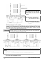
1-3-4
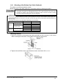
Sensor Placement
This is the configuration when two or more sets of emitter and receiver facing each other are
placed without series or parallel connection between them. It is used for the case that there is
a problem in wiring or for system evaluation in case of addition of equipment. Perform an
operation test by referring to ‘1-6-2 Operation Test’.
・ Refer to the examples of sensor placement given below and understand them thoroughly
before installing the sensors. Improper sensor placement could cause sensor malfunction,
which can result in serious injury or death.
・ If this device is used in multiple sets, arrange them to avoid mutual interference. If mutual
interference occurs, it can result in serious injury or death.
<Example of sensor placement>
<Reference>
The above figures are just examples of sensor placement. If there are any questions or problems, please
contact our office.
SUNX Limited MJE-SF4B No.6084-00
- 18 -
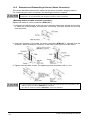
1-4 Mounting
1-4-1
Mounting of the Mounting Bracket
・ For selecting the appropriate mounting bracket matched to the installation environment, the
mounting bracket is not incorporated in this device. Please purchase the optional mounting
bracket to fit on the mounting environment.
・ Do not apply the load such as forced bending to the cable of this device. Applying improper
load could cause the wire breakage.
・ The minimum bending radius of the cable is R30mm. Mount the sensor considering the cable
bending radius.
<Reference>
・ Mount the emitter and the receiver at the same level and parallel to each other. The effective aperture angle
of this device is ±2.5゜
or less for a sensing distance exceeding 3m.
・ Unless otherwise specified, the following mounting procedure is common for both emitter and receiver. For
the preparation of the mounting, prepare the mounting holes on the mounting surface by referring to ‘5-3
Dimensions’.
<In case of using standard mounting bracket (MS-SFB-1) (optional)>
1. Loosen the hexagon-socket head bolt for alignment [M4 (length: 6mm)] of the standard
mounting bracket.
2. As shown in the figure below, adjust the direction of this device and that of installation
surface by declining the bracket, and tighten and fix the hexagon-socket head bolt for
alignment. The tightening torque should be 2N・m or less.
The marks are engraved on the standard mounting bracket so as to adjust the direction of
this sensor by 30 degrees. Set and fix both emitter and receiver using the marks so that
they face to each other.
Refer to ‘1-6-1 Beam-axis Alignment’ for details of the beam-axis alignment.
SUNX Limited MJE-SF4B No.6084-00
- 19 -
3. Set the device with its mounting hole on the side just overlapping with the mounting hole
of the standard mounting bracket, and fix the standard mounting bracket with the
accessory hexagon-socket head bolt [M5 (length: 15mm)]. The tightening torque should
be 1.2N・m or less.
4. Set the standard mounting bracket that is ready for setting to the mounting surface using
either four hexagon-socket head bolts [M5 (please arrange separately)] or two
hexagon-socket head bolts [M8 (please arrange separately)].
Note: For the models that the intermediate supporting bracket (MS-SFB-2) is enclosed with, be sure to use the
intermediate supporting bracket (MS-SFB-2). For details, refer to <In case of using intermediate
supporting bracket (MS-SFB-2) (Accessory)>
SUNX Limited MJE-SF4B No.6084-00
- 20 -
<In case of using dead spaceless bracket (MS-SFB-3) (Optional)>
1. Set the spacer attached to the dead spaceless bracket (MS-SFB-3) onto the mounting
hole on the side of the top (bottom) end part of this device, and insert the hexagon-socket
head bolt [M4 (length: 25mm)] into the hole.
2. Adjust the hexagon-socket head bolt with the status described in Step 1 to the mounting
hole of the dead spaceless bracket, and tighten and fix the bracket. The tightening torque
should be 1.2N・m or less.
3. Set the dead spaceless bracket that is ready for setting to the mounting surface using four
hexagon-socket head bolts [M5 (please arrange separately)].
Note: For the models that the intermediate supporting bracket (MS-SFB-2) is enclosed with, be sure to use the
intermediate supporting bracket (MS-SFB-2). For details, refer to <In case of using intermediate
supporting bracket (MS-SFB-2) (Accessory)>
SUNX Limited MJE-SF4B No.6084-00
- 21 -
<In case of using intermediate supporting bracket (MS-SFB-2) (Accessory)>
1. Loosen the hexagon-socket head bolt [M4 (length:12mm)] screw of the intermediate
supporting bracket (MS-SFB-2).
2. Insert the side of this device into the intermediate supporting bracket, and fix it with the
hexagon-socket head bolt [M4 (length: 12mm)]. The tightening torque should be 1.2N・m or
less.
Refer to ‘5-3 Dimensions’ for the mounting position of the intermediate supporting
bracket.
When setting the intermediate supporting bracket on both side surfaces of this device, fit
the four pits and projectiles of both side surfaces of the main body to those of both side
surfaces (inner surfaces) of the intermediate supporting bracket.
3. After aligning the beam axis, mount the intermediate supporting bracket to the mounting
surface using two hexagons-socket head bolts [M5 (please arrange separately)].
For the details of beam axis alignment, refer to ‘1-6-1 Beam-axis Alignment’.
SUNX Limited MJE-SF4B No.6084-00
- 22 -
1-4-2
Mounting of the Bottom Cap Cable (Optional)
The cable is not enclosed with this device.
Mount the bottom cap cable (optional) in accordance with the following procedure.
・ Do not lose any screws during extension / dismantling.
・ The bottom cap cables are distinguished with the color of the connectors, the color of the
connector for emitter is gray and that of the receiver is black. Connect the cable to emitter
and receiver without fail using their colors as the guide.
<Reference>
There are two types of the bottom cap cable, 8-core type and 12-core type, and in addition to these types, two
more types are available for the bottom cap cable, discrete wire type and connector type. Select the bottom cap
cable as usage.
The length of the bottom cap cable differs depending on the model No.
Type
Discrete wire type
8-core
Connector type
12-core
Discrete wire type
Connector type
Model No.
SFB-CCB3
SFB-CCB7
SFB-CB05
SFB-CB5
SFB-CB10
SFB-CCB3-MU
SFB-CCB7-MU
SFB-CB05-MU
Cable length (m)
3
7
0.5
5
10
3
7
0.5
<Mounting method>
1. Insert the connector of the bottom cap cable (optional) into the connector of this device.
When inserting the connector, fit the cable to the groove of this device.
2. Tighten the two M2.6 screws. The tightening torque should be 0.3N・m or less.
SUNX Limited MJE-SF4B No.6084-00
- 23 -
1-4-3
Extension and Dismantling of Sensor (Series Connection)
This section describes the extension method of the series connection using the options.
For constructing the series connection, the following procedure is required.
Do not lose any screws during extension / dismantling.
Furthermore, do not mix emitters and receivers to mount in series connection.
<Mounting method of cable for series connection>
Replace the cable for series connection (SFB-CSL□).
1. Loosen the two M2.6 screws of the end cap on the main side sensor (emitter and receiver
to which the synchronization line has been connected), and then remove the end cap
from the sensor.
2. Insert the connector of the cable for series connection (SFB-CSL□) (optional) into the
connector. When inserting the connector, fit the cable into the groove of this device.
3. Tighten each two M2.6 screws. The tightening torque should be 0.3N・m or less.
・ Take care that the shape of the connectors for the bottom side and for the end cap side on the
cable for series connection (SFB-CSL□) is different.
・The cable for series connection (SFB-CSL□) cannot be extended.
SUNX Limited MJE-SF4B No.6084-00
- 24 -
<Reference>
There is no difference in the cable for series connection for the emitter and the receiver.
The length of the cable for series connection differs depending on the model No.
Model No.
SFB-CSL01
SFB-CSL05
SFB-CSL1
SFB-CSL5
Cable Length (mm)
100
500
1,000
5,000
<Dismantling the cable for series connection>
1. For dismantling the cable for series connection, follow the above procedure of <Mounting
method of cable for series connection> in reverse.
SUNX Limited MJE-SF4B No.6084-00
- 25 -
1-5 Wiring
・ Earth the machine or the support where the sensor is mounted on to frame ground (F.G.).
Failure to do so could cause the malfunction of the product by noise, resulting in serious
injury or death.
Furthermore, the wiring should be done in a metal box connected to the frame ground (F.G.).
・ Take countermeasure against the system to be applied for this device so as not to carry out
the dangerous performance caused by the earth failure. Failure to do so could cause invalid
for the system stop, resulting in serious body injury or death.
Make sure to insulate the ends of the unused lead wires.
<Reference>
Use a safety relay unit or an equivalent control circuit in safety for FSD.
1-5-1
Power Supply Unit
Wire correctly using a power supply unit which conforms to the laws and standards of the region
where this device is to be used. If the power supply unit is non-conforming or the wiring is
improper, it can cause damage or malfunction of this device.
<Reference>
A specialist who has the required electrical knowledge should perform the wiring.
The DC power supply unit must satisfy the conditions given below.
1) Power supply unit authorized in the region where this device is to be used.
2) Power supply unit conforming to EMC Directive and Low-voltage Directive (only for requiring CE
conformation).
3) Power supply unit conforming to the Low-voltage directive and with an output of 100VA or less.
4) The frame ground (F.G.) terminal must be connected to ground when using a commercially available
switching regulator.
5) Power supply unit with an output holding time of 20ms or more.
6) In case a surge is generated, tale countermeasures such as connecting a surge absorber to the origin of
the surge.
7) Power supply unit corresponding to CLASS 2 (only for requiring C-UL conformation)
《Additional information》As provided in IEC 60536 (CLASS: Protection against Electric Shock), this
power supply should require no ground earth and satisfy the insulation
distance called double insulation or reinforced insulation.
In case the power supply conforms to Low-voltage directive and has an
output of 100VA or less, it can be used as a suitable product.
SUNX Limited MJE-SF4B No.6084-00
- 26 -
1-5-2
I/O Circuit Diagrams
<In case of using I/O circuit for PNP output>
*S1
Switch S1 (connectable either to +V or 0V)
・ Emission halt input / Reset input
For manual reset: 0 to +1.5V or Vs to Vs-2.5V: Emission halt (sink current 5mA or less) (Note),
Open: Emission
For auto-reset: 0 to +1.5V or Vs to Vs-2.5V: Emission (sink current 5mA or less) (Note),
Open: Emission halt
・ Interlock setting input, Override input, Muting input A / B, External device monitor input
0 to +1.5V or Vs to Vs-2.5V: Valid (sink current 5mA or less) (Note), Open: Invalid
Note: Vs is the applying supply voltage.
<Reference>
K1, K2: External device
SUNX Limited MJE-SF4B No.6084-00
- 27 -
<In case of using I/O circuit for NPN output>
*S1
Switch S1 (connectable either to +V or 0V)
・ Emission halt input / Reset input
For manual reset: 0 to +1.5V or Vs to Vs-2.5V: Emission halt (source current 5mA or less) (Note),
Open: Emission
For auto-reset: 0 to +1.5V or Vs to Vs-2.5V: Emission (source current 5mA or less) (Note),
Open: Emission halt
・ Interlock setting input, Override input, Muting input A / B, External device monitor input
0 to +1.5V or Vs to Vs-2.5V: Valid (source current 5mA or less) (Note), Open: Invalid
Note: Vs is the applying supply voltage.
<Reference>
K1, K2: External device
SUNX Limited MJE-SF4B No.6084-00
- 28 -
<Output waveform [control output (OSSD 1, OSSD 2) ON]>
Since the receiver performs the self-diagnosis of the output circuit when the sensor is in light
receiving status (ON status), the output transistor becomes OFF status periodically. (Refer to
the figure below.)
When the OFF signal is fed back, the receiver judges the output circuit as normal. When the
OFF signal is not fed back, the receiver judges either the output circuit or wiring as error, and
the control output (OSSD 1, OSSD 2) maintains OFF status.
Since the OFF signal of this device might cause malfunction, perform the connecting paying
attention to the input response time of the machine to be connected to this device.
1-5-3
Wiring・Connecting Procedure
Connect the mating cable (with connector on one end, or connector on both ends) to the
connector of the sensor main body (emitter and receiver).
Wire the other side of the mating cable according to the customer’s application referring to the
connector pin arrangement given below and to ‘1-5-4 Wiring for Manual Reset (Interlock is Valid)’.
・ When extending the cable, use the exclusive cable up to the total length of 50m (for emitter /
receiver). Extending the cable longer than 50m may cause malfunction, which can result in
serious injury or death. Besides, if the 2 sets of the sensors are connected in series, up to
total length of 30m (for emitter / receiver) is allowed for use, and if the 3 sets of the sensors
are connected, up to total length of 20m (for emitter / receiver) is allowed for use. Extending
the cable longer than the length specified may cause malfunction, which can result in serious
injury or death.
・ In case the muting indicator is used, a total length should be 40m or less. (for emitter /
receiver)
・ When the synchronization cable is extended with a cable other than exclusive cable, use a
φ0.2mm2 or more shielded twist pare cable.
SUNX Limited MJE-SF4B No.6084-00
- 29 -
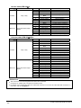
<8-core cable (SFB-CC□)>
Cable / connector color
Emitter
Receiver
Pin No.
1
2
3
4
Gray / Gray
5
6
7
8
1
2
3
4
5
6
7
8
Gray (with black stripe) /
Black
Lead wire color
Pale purple
Brown
Pink
Yellow-green /
Black
Orange
Orange / Black
Blue
(Shield)
White
Brown
Black
Yellow-green
Orange
Orange / Black
Blue
(Shield)
Description
Interlock setting input
24V DC
Emission halt input / Reset input
Lead wire color
Pale purple
Brown
Pink
Yellow-green /
Black
Orange
Orange / Black
Blue
(Shield)
Gray
Gray / Black
Yellow
Red
White
Brown
Black
Yellow-green
Orange
Orange / Black
Blue
(Shield)
Gray
Gray / Black
Sky-blue / White
Sky-blue / Black
Description
Interlock setting input
24V DC
Emission halt input / Reset input
Auxiliary output
Synchronization +
Synchronization 0V
Output polarity setting wire
Control output 2 (OSSD 2)
24V DC
Control output 1 (OSSD 1)
External device monitor input
Synchronization +
Synchronization -
0V
Output polarity setting wire
<12-core cable (SFB-CC□-MU)>
Cable / connector color
Pin No.
1
2
3
4
Emitter
Receiver
Gray / Gray
Gray (with black stripe) /
Black
5
6
7
8
9
10
11
12
1
2
3
4
5
6
7
8
9
10
11
12
Auxiliary output
Synchronization +
Synchronization 0V
Output polarity setting wire
Interference prevention +
Interference prevention Override input
Muting lamp output
Control output 2 (OSSD 2)
24V DC
Control output 1 (OSSD 1)
External device monitor input
Synchronization +
Synchronization 0V
Output polarity setting wire
Interference prevention +
Interference prevention Muting input A
Muting input B
<Reference>
・ The connectors can be distinguished from their color as follows:
Connector for emitter: gray, connector for receiver: black
・ For details of the bottom cap cable, the cable with connector on one end, and the cable with connector on
both ends, refer to ‘5-2 Options’.
SUNX Limited MJE-SF4B No.6084-00
- 30 -
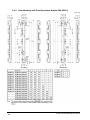
1-5-4
Wiring for Manual Reset (Interlock is Valid)
<For PNP output>
This is the general configuration using one set of the emitter and receiver facing each other.
The control output (OSSD 1, OSSD 2) turns OFF if the light is blocked.
The sensor output is selected depending on
the connecting state of the shield wire
Incorrect wiring may cause the lockout state.
*Symbols
Switch S1
(Connectable either to +V or 0V)
0 to +1.5V or Vs to Vs-2.5V: Emission halt
(sink current 5mA or less) (Note 1)
Open: Emission
K1, K2: External device
Notes: 1) Vs is the applying supply voltage.
2) For resetting, refer to ‘2-5 Interlock
Function’.
<For NPN output>
The sensor output is selected depending on
the connecting state of the shield wire.
Incorrect wiring may cause the lockout state.
*Symbols
Switch S1
(Connectable either to +V or 0V)
0 to +1.5V or Vs to Vs-2.5V: Emission halt
(source current 5mA or less) (Note 1)
Open: Emission
K1, K2: External device
Notes: 1) Vs is the applying supply voltage.
2) For resetting, refer to ‘2-5 Interlock
Function’.
<Series connection (for PNP output)>
[Connectable up to 3 sets of sensors (however, 192 beam channels max.)]
This is the configuration for connecting multiple sets of emitters and receivers facing each
other in series. It is used when the dangerous part can be entered from two or more
directions. The control output (OSSD 1, OSSD 2) turns OFF if the light is blocked.
For series connection, connect the emitter and emitter, receiver and receiver respectively using
the exclusive cable (SFB-CSL□) for series connection. Wrong connection could generate the
non-sensing area, resulting in serious injury or death.
SUNX Limited MJE-SF4B No.6084-00
- 31 -
The sensor output is selected depending on
the connecting state of the shield wire.
Incorrect wiring may cause the lockout
state.
*Symbols
Switch S1
(Connectable either to +V or 0V)
0 to +1.5V or Vs to Vs-2.5V: Emission halt
(sink current 5mA or less) (Note 1)
Open: Emission
K1, K2: External device
Notes: 1) Vs is the applying supply voltage.
2) For resetting, refer to ‘2-5 Interlock
Function’.
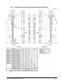
<Parallel connection (for PNP output)>
This is the configuration for connecting multiple sets of emitter and receiver facing each other
in parallel. It is used when there are two dangerous parts and each dangerous part can be
entered from only one direction. By connecting the interference prevention line, up to three
sets of the sensors can be connected. For the control output (OSSD 1, OSSD 2), only the
output of the sensor of which light is blocked turns OFF.
For parallel connection, connect the one receiver to the other connection using the interference
prevention line as shown in the figure below. Wrong connection could generate the
non-sensing area, resulting in serious injury or death.
The sensor output is selected depending on the connecting state of the shield wire. Incorrect wiring may cause the lockout state.
*Symbols
*Symbol
Switch S1
(Connectable either to +V or 0V)
0 to+1.5V or Vs to Vs-2.5V: Emission halt (sink current 5mA or less) (Note 2), Open: Emission
K1, K2: External device
Notes: 1) If the interference prevention wire is extended, use a φ0.2mm2, or more, shielded twist pair-cable.
2) Vs is the applying supply voltage.
3) For resetting, refer to ‘2-5 Interlock Function’.
SUNX Limited MJE-SF4B No.6084-00
- 32 -
<Series and parallel mixed connection (for PNP output)>
This is the configuration for connecting multiple sets of emitter and receiver facing each other
in mixed series and parallel combination. It is used when there are two or more dangerous
parts that can be entered from two or more directions. Up to three sets of sensors in total of
the series connection and parallel connection can be connected in combination. However,
max. 192 beam channels for each series connection are allowed. The control output (OSSD
1, OSSD 2) turns only its output to OFF if the light is blocked.
For parallel connection, connect the one receiver to the other connection using the interference
prevention line as shown in the figure below. Wrong connection could generate the non-sensing
area, resulting in serious injury or death.
The sensor output is selected depending on
the connecting state of the shield wire.
Incorrect wiring may cause the lockout
state.
*Symbols
Switch S1 (Connectable either to +V or 0V)
0 to+1.5V or Vs to Vs-2.5V: Emission halt (sink current 5mA or less) (Note 2), Open: Emission
K1, K2: External device
Notes: 1) If the interference prevention wire is extended, use a φ0.2mm2, or more, shielded twisted pair cable.
2) Vs is the applying supply voltage.
3) For resetting, refer to ‘2-5 Interlock Function’.
1-5-5
Wiring for Auto-reset (Interlock is Invalid)
<For PNP output>
The sensor output is selected depending on
the connecting state of the shield wire.
Incorrect wiring may cause the lockout state.
*Symbols
Switch S1
(Connectable either to +V or 0V)
0 to+1.5V or Vs to Vs-2.5V: Emission
(source current 5mA or less)
(Note)
Open: Emission halt
Note: Vs is the applying supply voltage.
SUNX Limited MJE-SF4B No.6084-00
- 33 -
1-5-6
Wiring Configuration for Invalid External Device Monitor Function
<For PNP output>
This is the configuration for connecting auxiliary output and external device monitor input.
At this time, set the auxiliary output with ‘negative logic of the control output (OSSD 1, OSSD
2)’ (factory setting). [Set through the handy-controller (SFB-HC) (optional)]
The sensor output is selected depending on
the connecting state of the shield wire.
Incorrect wiring may cause the lockout
state.
*Symbols
Switch S1
(Connectable either to +V or 0V)
0 to +1.5V or Vs to Vs-2.5V: Emission halt
(sink current 5mA or less) (Note 1)
Open: Emission
K1, K2: External device
It also enables the external device monitor function to be set at invalid by using the handy
controller (SFB-HC) (optional).
1-5-7
Connection Configuration When Using Muting Function
<For PNP output>
The sensor output is selected depending on
the connecting state of the shield wire.
Incorrect wiring may cause the lockout state.
*Symbols
Switch S1:
(Connectable either to +V or 0V)
0 to+1.5V or Vs to Vs-2.5V: Emission
(sink current 5mA or less) (Note 3)
Open: Emission halt
Switch S2:
The muting input, the override input
(Connectable either to +V or 0V)
0 to+1.5V or Vs to Vs-2.5V: Valid
(sink current 5mA or less) (Note 3)
Open: Invalid
Notes: 1) Be sure to connect the muting lamp. If the muting lamp is not connected, the muting function does
not operate.
2) In case of using this connection configuration for NPN output, connect the muting lamp output (red) to
0V (blue).
3) Vs is the applying supply voltage.
SUNX Limited MJE-SF4B No.6084-00
- 34 -
1-6 Adjustment
1-6-1
Beam-axis Alignment
1. Turn ON the power supply unit of this device.
2. Check that the digital error indicator (red) and the fault indicator (yellow) of the emitter and
receiver are off respectively.
・ If the digital error indicator (red) or the fault indicator (yellow) light up or blinks, refer to
‘Chapter 4 Troubleshooting’, and report the contents to the maintenance in charge.
3. In case of using the intermediate supporting bracket (MS-SFB-2), loosen the two
hexagon-socket head bolt [M5 (please arrange separately)].
4. In case of using the standard mounting bracket (MS-SFB-1) (otional) for mounting this
sensor, loosen the two hexagon-socket head bolt for alignment of the standard mounting
bracket so that the emitter and receiver face to each other.
The marks are engraved on the standard mounting bracket A, which enables the angle of
the emitter / receiver to be adjusted by 30 degrees.
5. Tighten the hexagon-socket head bolt for alignment of the standard mounting bracket. The
tightening torque should be 2N・m or less.
6. Loosen the hexagon-socket head bolt for beam axis alignment of the standard mounting
bracket, and adjust the emitter / receiver so that the beam-axis alignment indicators in the
display of the emitter and receiver light up.
The emitter and the receiver can be fine-adjusted by ±15 degrees.
SUNX Limited MJE-SF4B No.6084-00
- 35 -
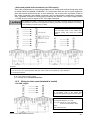
<Reference>
The beam-axis alignment indicator indicates the reception status for each section of a sensor which
is divided into 4 sections.
Also, the A (D) of the beam-axis alignment indicates the light-receiving status of the sensor top end (bottom
end).
For example, when using a 24-beam channel sensor, there are 6 beam channels per section (i.e., 24/4=6).
When the top end (bottom end) beam channel is received, the A (D) of the beam-axis alignment indicator blinks
in red.
(Example) 24 beam channels
All the 6 beam channels divided into each section are received, the bam-axis alignment indicator lights up in
red.
The indicators corresponding to the different sections light up in red, one by one, when the beam channels of
the respective sections are received. When all the bam channels are received and the control output (OSSD 1,
OSSD 2) turns ON, all the four indicators of the beam-axis alignment indicator turn into green.
Refer to ‘1-6-3 Operation’ for details.
7. After the adjustment, tighten the hexagon-socket head bolt for beam axis alignment of the
standard mounting bracket. The tightening torque should be 2N・m or less.
8. Tighten the two intermediate supporting brackets [M5 (please arrange separately)].
Check, once again, that the beam-axis alignment indicators in the display of the emitter
and receiver do light up.
SUNX Limited MJE-SF4B No.6084-00
- 36 -
1-6-2
Operation Test
1 Turn ON the power supply unit of this device.
2. Check that the digital error indicator (red) and the fault indicator (yellow) of the emitter and
the receiver are off respectively.
・ If the digital error indicator (red) or the fault indicator (yellow) lights up or blinks, refer to
‘Chapter 4 Troubleshooting’, and report the contents to the maintenance in charge.
3. Move the test rod up and down at three positions, just in front of the emitter (A), between
the emitter and receiver (B), and just in front of the receiver (C).
Test rod
4. During Step 3 above, check that the control output (OSSD 1, OSSD 2) is in OFF status,
and both the OSSD indicator (red) of the receiver and the operation indicator (red) of the
emitter light up as long as the test rod is present within the sensing area.
・ If the behavior of the control output (OSSD 1, OSSD 2) and the turning ON/OFF of the
emitter / receiver indicators do not correspond to the movement of the test rod, refer to
‘Chapter 4 Troubleshooting’, and report the contents to the maintenance in charge.
<Reference>
If the indicators show reception of the light even though the test rod blocks the light, check whether there is any
reflective object or extraneous light source near this device or not.
SUNX Limited MJE-SF4B No.6084-00
- 37 -
1-6-3
Operation
1) Normal Operation
The status of the emitter / receiver indicators during normal operation is as described
below.
Device Status
Indicators
Emitter
Lights up in green
Receiver
Lights up in green
Reception status
(all beams received)
ON
Beam blocked status
Lights up in red
(OFF for beam blocked
channels)
One or more
beams
blocked
OSSD
OSSD 1
OSSD 2
Lights up in red
(OFF for beam blocked
channels)
OFF
Notes: 1) Since the color of the operation indicator changes according to the ON / OFF state of the control
output (OSSD 1, OSSD 2), the operation indicator is marked as OSSD on the sensor.
2) The status of the emitter / receiver indicators during operation above shows the case in PNP
output setting mode. In case of NPN output setting mode, the NPN indicator (orange) lights up.
SUNX Limited MJE-SF4B No.6084-00
- 38 -
Device Status
Indicators
Emitter
Receiver
The top most beam-axis The top most beam-axis
alignment indicator:
alignment indicator:
blinks in red
blinks in red
Operation indicator:
Operation indicator:
lights up in red
lights up in red
OSSD
OSSD 1
OSSD 2
Beam blocked status
Beams other
than the top
end blocked
The bottom most beam
-axis alignment indicator:
blinks in red
Operation indicator:
Lights up in red
The bottom most beam
-axis alignment indicator:
blinks in red
Operation indicator:
lights up in red
OFF
Beams other
than the
bottom end
blocked
Time chart
Notes: 1) Since the color of the operation indicator changes according to the ON / OFF state of the control
output (OSSD 1, OSSD 2), the operation indicator is marked as OSSD on the sensor.
2) The status of the emitter / receiver indicators during operation above shows the case in PNP
output setting mode. In case of NPN output setting mode, the NPN indicator (orange) lights up.
SUNX Limited MJE-SF4B No.6084-00
- 39 -
<For series connection>
In case of series connection, if any of the sets is in the beam blocked status, the control
output (OSSD 1, OSSD 2) turns OFF.
<Reference>
The emitter / receiver indicators indicate the output status.
The following figure shows the status of the indicators with A2 (Sub Sensor1) in light blocked
status.
Notes: 1) Since the color of the operation indicator changes according to the ON / OFF state of the control
output (OSSD 1, OSSD 2), the operation indicator is marked as OSSD on the sensor.
2) The status of the emitter / receiver indicators during operation above shows the case in PNP output
setting mode. In case of NPN output setting mode, the NPN indicator (orange) lights up.
SUNX Limited MJE-SF4B No.6084-00
- 40 -
2) In case of using emission halt function
This device incorporates the emission halt function. Using this function, it is possible to
simulate the beam blocked status.
<Reference>
When the emission halt input is kept open or connected to 0 to +1.5V, the emitter stops emitting light. In this
condition, if this device operates properly, the control output (OSSD 1, OSSD 2) of the receiver turns OFF.
Setting procedure
and check items
Indicators
Emitter
Receiver
OSSD
OSSD 1
OSSD 2
1
Before power
is ON
Connect the
emission halt
input to Vs
(Note 3)
OFF
2
After power is
ON
Receiver’s
control output
(OSSD 1, OSSD 2)
ON
(Normal
operation)
ON
Notes: 1) Since the color of the operation indicator changes according to the ON/OFF state of the control
output (OSSD 1, OSSD 2), the operation indicator is marked as OSSD on the sensor.
2) The status of the emitter / receiver indicators during operation above shows the case in PNP
output setting mode. In case of NPN output setting mode, the NPN indicator (orange) lights up.
3) Vs is the applying supply voltage.
SUNX Limited MJE-SF4B No.6084-00
- 41 -
Setting procedure
and check items
Indicators
Emitter
Receiver
OSSD
OSSD 1
OSSD 2
3
Open the
emission halt
input
Receiver’s
control output
(OSSD 1, OSSD 2)
is OFF
(Emission halt)
(Normal
operation)
OFF
4
Connect the
emission halt
input to Vs
(Note 3)
Receiver’s
control output
(OSSD 1, OSSD 2)
is ON
(Normal
operation)
ON
Notes: 1) Since the color of the operation indicator changes according to the ON/OFF state of the control
output (OSSD 1, OSSD 2), the operation indicator is marked as OSSD on the sensor.
2) The status of the emitter / receiver indicators during operation above shows the case in PNP
output setting mode. In case of NPN output setting mode, the NPN indicator (orange) lights up.
3) Vs is the applying supply voltage.
SUNX Limited MJE-SF4B No.6084-00
- 42 -
3) In case of abnormal operation
If a sensor error is detected, the sensor will turn the control output (OSSD 1, OSSD 2) off
and the digital error indicator (red) lights up and the fault indicator (yellow) lights up or
blinks.
・ If an emitter error is detected, the emitter will be locked out, stopping its emission, and
the control output (OSSD 1, OSSD 2) will be turned OFF.
・ If a receiver error is detected, the receiver will be locked out, and the control output
(OSSD 1, OSSD 2) will go into OFF state. Also, the emission halt indicator (orange) of
the emitter blinks.
<Emitter>
<Receiver>
Notes: 1) Since the color of the operation indicator changes according to the ON/OFF state of the control
output (OSSD 1, OSSD 2), the operation indicator is marked as OSSD on the sensor.
2) Refer to ‘Chapter 4 Troubleshooting’ for details of the digital error indicator.
3) The status of the emitter / receiver indicators during operation above shows the case in PNP output
setting mode. In case of NPN output setting mode, the NPN indicator (orange) lights up.
Since this device will not return to normal operation automatically after the removal of the
source of error, it is necessary to turn the power off and on again.
(Source of error): The control output (OSSD 1, OSSD 2) short-circuit, extraneous light
detection, sensor failure, etc.
Refer to ‘Chapter 4
Troubleshooting’ and remove the source of error.
SUNX Limited MJE-SF4B No.6084-00
- 43 -
Chapter 2 Functions
2-1 Self-diagnosis Function
This device is equipped with the self-diagnosis function. The self-diagnosis is carried out
when the power is turned ON and while the operation periodically.
In case an abnormality is detected during self-diagnosis, the device is put in the lockout state
at that instant, and the control output (OSSD 1, OSSD 2) is fixed at the OFF state. Refer to
‘Chapter 4 Troubleshooting’ and remove the cause of the abnormality.
2-2 Emission Halt Function
This function stops the emission process of the emitter.
With the emission halt input line state, it enables to select either emission or emission halt.
Setting status of
interlock function
Auto reset
Manual reset
Emission halt input
Emission status
Open
0V, +V connection
Open
0V, +V connection
Emission halt
Emission
Emission
Emission halt
During emission halt, the control output (OSSD 1, OSSD 2) becomes OFF status.
By using this function, malfunction due to extraneous noise or abnormality in the control
output (OSSD 1, OSSD 2) and the auxiliary output can be determined even from the
equipment side.
Normal operation is restored when the emission halt input / reset input is connected to 0V
(+V for NPN output).
Note: This timing chart shows the operation in auto-reset mode. In manual reset mode, the device performs
emission under open status and performs emission halt under short-circuit status.
Do not use the emission halt function for the purpose of stopping the device. Failure to do so
could result in serious injury or death.
2-3 Interference Prevention Function
It is possible to construct the system to prevent malfunction due to interference of the light
between SF4B series devices.
The interference prevention system can construct max. three sets of series connection.
The max. number of the beam channels in series connection is 192.
Refer to ‘1-5 Wiring’ for details of the connecting method.
SUNX Limited MJE-SF4B No.6084-00
- 44 -
2-4 Auxiliary Output (Non-safety Output)
This device incorporates the auxiliary output for the non-safety output.
The auxiliary output is incorporated with the emitter.
Auxiliary output setting
Emission halt
Negative logic of OSSD
(Factory setting)
Normal mode
Control output (OSSD 1, OSSD 2) status
Beam received
Beam blocked
ON
OFF
ON
Lockout
ON
Do not use the auxiliary output for the purpose of stopping the device. Failure to do so could
result in serious injury or death.
<Reference>
It is possible to switch the output operation for auxiliary output by using the handy controller (SFB-HC) (optional).
2-5 Interlock Function
The selection of manual reset / auto reset is available by applying the interlock input wiring.
The interlock becomes available by selecting manual reset.
Input status
Interlock setting
Open
0V, +V connection
Setting for interlock function
Auto reset
Manual reset
Manual reset: The control output (OSSD 1, OSSD 2) is not turned ON automatically even
though this device is received the light. When this device is reset in light
received state [open the emission halt input / reset input→short-circuit the
device to 0V (+V for NPN output selected)→open], the control output (OSSD
1, OSSD 2) is turned ON.
Auto-reset: The control output (OSSD 1, OSSD 2) is turned ON automatically when this
device receives the light.
SUNX Limited MJE-SF4B No.6084-00
- 45 -
In case that this device is used under auto-reset mode, set the system not to be auto reset by
the safety relay unit, etc. (conforming to EN 60204-1)
<Reference>
It is possible to change the condition for interlock by using the handy controller (SFB-HC) (optional).
2-6 External Device Monitor Function
This is the function for checking whether the external safety relay connected to the control
output (OSSD 1, OSSD 2) performs normally in accordance with the control output (OSSD 1,
OSSD 2) or not. Monitor the contacting point ‘b’ of the external safety relay, and if any
abnormality such as deposit of the contacting point, etc. is detected, change the status of the
sensor into lockout one, and turn OFF the control output (OSSD 1, OSSD 2).
・
In case of setting the external device monitor function into valid:
Connect the external device monitor input line to the external safety relay connected the
control output (OSSD 1, OSSD 2).
・
In case of not using the external device monitor function:
Connect the external device monitor input line to the auxiliary output line. At this time, the
auxiliary output is set as [negative logic of control output (OSSD 1, OSSD 2)] (factory
setting) [Set through the handy controller (SFB-HC) (optional)]
<Reference>
It is also possible to set the external device monitor function into invalid by using the handy controller (SFB-HC)
(optional).
The setting time of the device monitor is 300ms or less. Exceeding 300ms turns the device
into lockout status. It can be set within 100 to 600ms (unit: 10ms) by using the handy
controller (SFB-HC)(optional).
SUNX Limited MJE-SF4B No.6084-00
- 46 -
2-7 Muting Function
・Incorrect using of the muting control may cause any accident. Please understand the muting
control fully, and use it. As for the muting control, the following international standards define
the requirements.
ISO 13849-1(EN 954-1 / JIS B 9705-1):
‘Safety of machinery -- Safety-related parts of control systems -- Part 1: General principles for
design, Article 5.9 Muting’
IEC 61496-1 (UL 61496 / JIS B 9704-1):
‘Safety of machinery -- Electro sensitive protective equipment -- Part 1: General requirements
and tests’ Annex A, A.7 Muting
IEC 60204-1 (JIS B 9960-1):
‘Safety of machinery -- Electrical equipment of machines - Part 1: General requirements, 9.2.4
Overriding safeguards’
EN 415-4:
‘Safety of packaging machines part 4. Palletizers and depalletizers’ Annex A, A2.2 Muting’
ANSI B11.19-1990:
‘for Machine Tools-Safeguarding When Referenced by the Other B11 Machine Tool Safety
Standards-Performance Criteria for the Design, Construction, Care, and Operation’ 4.2.3
Presence-Sensing Devices: Electro-Optical and Radio Frequency (R.F.)
ANSI/RIA R15.06-1999:
‘for Industrial Robots and Robot Systems - Safety Requirements, 10.4.5 Muting’
・ Use the muting control while the machine cycle is not in danger mode. Maintain safety with
the other measure while the muting control is activated.
・ For the application that the muting control is activated when a workpiece passes through the
sensor, place the muting sensor so that the conditions for the muting control cannot be
satisfied by intrusion of personnel when the workpiece is passing through the sensor or the
workpiece is not passing through it.
・ The muting lamp should be installed in a position where it can always be seen by operators
who set or adjust the machine.
・ Be sure to check the operation of the muting function before its use. Furthermore, check the
state of the muting lamp (cleanliness or brightness etc.)
This function turns the safety function of this device into invalid temporarily. When the control
output (OSSD 1, OSSD 2) is ON, this function is available for passing the workpiece through
the sensing area of the sensor without stopping the device.
The muting function becomes valid when all the conditions listed below are satisfied:
・ The control output (OSSD 1, OSSD 2) shall be ON.
・ The incandescent lamp with 3 to 10W shall be connected to the muting lamp output.
・ The output of the muting sensors A, B, C, and D shall be changed from OFF (open) to
ON. At this time, the time difference occurred by changing the output of the muting
sensors A, B, C, and D into ON status shall be within 0.03 to 3 sec.
The following devices, photoelectric sensor with semiconductor output, proximity sensor,
position switch on NO (Normal Open) contacting point, etc. are available for applying to the
muting sensor.
SUNX Limited MJE-SF4B No.6084-00
- 47 -
<Specification for muting sensor>
ON with beam non-received
status (photoelectric sensor, etc.)
ON with object approaching
status (proximity sensor, etc.)
ON with object contacted status
(position switch, etc.)
Performance with ON status
Performance with OFF status
Output 0V (+V for selected NPN
output)
Open
・ Be sure to use the muting sensor that satisfies the <Specification for muting sensor> above. If
the other muting sensor not satisfying the specification above, the muting function might
become valid with the timing that the machine designer cannot expect and could result in
serious injury or death.
・ The muting lamp shall be connected without fail. The muting function is invalid for activating
with the muting lamp not connected.
<Installation condition of muting sensor>
① Shorten the distances between muting
sensors A to C and between B to D than the
whole length of the sensing object.
② The moving speed of the sensing object to
be passed through the muting sensors A to
B shall be 30ms to 3 sec.
Distance between A and B: S×3 (s)
③ The moving speed of the sensing object to
be passed through the muting sensors C to
D shall be under 3 sec.
Distance between C and D: S×3 (s)
SUNX Limited MJE-SF4B No.6084-00
- 48 -
Note: In case the muting lamp does not light up even after more than 1 sec. passed, the muting function
becomes invalid.
<Reference>
・ It is possible to set the muting function into invalid per beam channel respectively and to specify the output
order of the muting sensor to be set into valid by using the handy controller (SFB-HC) (optional).
・ It is recommended that two muting lamps should be connected in parallel. However, take care not to exceed 10W.
SUNX Limited MJE-SF4B No.6084-00
- 49 -
2-8 Override Function
・Incorrect using of the muting control may cause any accident. Please understand the muting
control fully, and use it. As for the muting control, the following international standards define
the requirements.
ISO 13849-1(EN 954-1 / JIS B 9705-1):
‘Safety of machinery -- Safety-related parts of control systems -- Part 1: General principles for
design, Article 5.9 Muting’
IEC 61496-1 (UL 61496 /JIS B 9704-1):
‘Safety of machinery -- Electro sensitive protective equipment -- Part 1: General requirements
and tests’ Annex A, A.7 Muting
IEC 60204-1 (JIS B 9960-1)
‘Safety of machinery -- Electrical equipment of machines - Part 1: General requirements, 9.2.4
Overriding safeguards’
EN 415-4:
‘Safety of packaging machines part 4. Palletizers and depalletizers’ Annex A, A2.2 Muting
ANSI B11.19-1990:
‘for Machine Tools-Safeguarding When Referenced by the Other B11 Machine Tool Safety
Standards-Performance Criteria for the Design, Construction, Care, and Operation’ 4.2.3
Presence-Sensing Devices: Electro-Optical and Radio Frequency (R.F.)
ANSI/RIA R 15.06-1999:
‘for Industrial Robots and Robot Systems - Safety Requirements, 10.4.5 Muting’
・ Use the muting control while the machine cycle is not in danger mode. Maintain safety with
the other measure while the muting control is activating.
・ For the application that the muting control is activated when a workpiece passes through the
sensor, place the muting sensor so that the conditions for the muting control cannot be
satisfied by intrusion of personnel when the workpiece is passing through the sensor or the
workpiece is not passing through it.
・ The muting lamp should be installed in a position where it can always be seen by operators
who set or adjust the machine.
・ Be sure to check the operation of the muting function before its use. Furthermore, check the
state of the muting lamp (cleanliness or brightness etc.)
This function sets the safety function of this device invalid forcibly. This function is used for
the following cases: when the customer who uses the muting function needs to start the
device with the control output (OSSD 1, OSSD 2) be OFF status, when the device is required
to continue operating even though the muting sensor becomes valid after the muting sensor
is turned ON at the starting of line.
The override function becomes valid when all the conditions listed below are satisfied:
・ The incandescent lamp with 3 to 10W shall be connected to the muting lamp output.
・ The signal shall be input to either muting sensor A or B.
・ The override input shall be short-circuited to 0V (+V for NPN output selected), and the
emission halt input / reset input shall be opened. (3 sec. continuously)
If one of the three conditions above becomes invalid or timing exceeds 60 sec., the override
function becomes invalid.
SUNX Limited MJE-SF4B No.6084-00
- 50 -
Note: In case the muting lamp does not light up even after more than 4 sec. passed, the muting function
becomes invalid.
SUNX Limited MJE-SF4B No.6084-00
- 51 -
2-9 Functions Using Handy Controller (SFB-HC) (Available soon)
This device enables to set each function using the handy controller (SFB-HC) (optional). The
settable functions are as follows.
Refer to the instruction manual enclosed with the handy controller for details of the function settings.
Among the functions, the contents related to the safety distance such as the size of the
minimum sensing object and response time are varied depending on the setting condition.
When setting each function, re-calculate the safety distance, and make enough space larger
than the calculated safety distance. Failure to do so might cause the accident that the device
cannot stop quickly before reaching the dangerous area of the device, resulting in the serious
・
・
Fixed blanking function
This function enables to protect the control output (OSSD 1, OSSD 2) from turning into
OFF even though the specific beam channel is blocked.
The factory setting is set to invalid for the fixed blanking function.
Floating blanking function
This function enables to protect the control output (OSSD 1, OSSD 2) from turning into
OFF even though the number of the blocked beam channels are lower than that of the
setting beam channels. 1, 2, or 3 beam channels are settable as the blocking beam
channels.
Both fixed blanking function and floating blanking function are settable simultaneously.
The factory setting is set to invalid for the floating blanking function.
・ Emission intensity control function
The two modes, normal mode and short mode, can be set / changed by controlling the
emission intensity.
The factory setting is set to the normal mode for the emission intensity control function.
・ Auxiliary output switching function (non-safety output)
The following outputs are switchable as the auxiliary output.
0. Negative logic of the control output (OSSD 1, OSSD 2) (factory setting)
1. Positive logic of the control output (OSSD 1, OSSD 2)
2. For emission: output OFF, For non-emission: output ON
3. For emission: output ON, For non-emission: output OFF
4. For unstable incident beam: OFF (Note 1)
5. For unstable incident beam: ON (Note 1)
6. For muting: ON
7. For muting: OFF
8. For beam reception: ON, For beam blocked: OFF (Note 2)
9. For beam reception: OFF, For beam blocked: ON (Note 2)
Notes: 1) The output cannot be used while the fix blanking function, floating blanking function or the muting
function is activated.
2) This device outputs the beam reception / blocked state under activating the auxiliary output
switching function using the handy controller irrespective of activating other functions, fixed blanking
function, floating function, floating blanking function, and muting function.
<e.g.>
In case of activating the fixed blanking function, the control output (OSSD 1, OSSD 2) becomes
ON with the shielded object existed in the setting range and other ranges are in beam receiving
status. If the auxiliary output switching function activates in No. 8 output, this device becomes
OFF because the sensor itself detects the object.
・
Interlock setting changing function
It is selectable one interlock state among the following three interlock settings.
・
Start interlock
The sensor goes into the interlock state when the power supply is turned on. Once this
interlock is reset, the device does not go into the interlock state.
・
Restart interlock
The sensor does not go into the interlock state when turning on the power supply. Only when
the control output (OSSD 1, OSSD 2) becomes ON and the light is blocked after the power is
turned on and this device receives the light, the sensor goes into the interlock state.
SUNX Limited MJE-SF4B No.6084-00
- 52 -
・
Start / Restart interlock
The sensor goes into the interlock state after the power is turned on, and the light is
blocked.
The factory setting is start / restart interlock.
・
External device monitor setting changing function
The setting of the external device monitor is changeable.
1. Allowable time for response time: 100 to 600ms (Unit: 10ms)
Factory setting is 300ms.
2. The external device monitor function can be selected to valid or invalid.
The factory setting is set to valid for the external device monitor function.
・
Muting setting changing function
The setting of the muting function is changeable.
1. When the muting function becomes valid, the output order of the muting sensors A and
B are possible to be specified.
Either of muting sensors A or B is valid as the factory setting.
2. The muting function can be selected to valid / invalid per beam channel. (Note)
The factory setting of the muting function is set to valid for all beam channels.
Note: When the light is blocked on the beam channel set as the muting function invalid while the muting
function is active, the control output (OSSD 1, OSSD 2) is turned off and the muting function
becomes invalid.
・
Protect function
Unless the password is not input, any setting change of the sensor cannot be allowed.
The factory setting is set to invalid for the protect function.
SUNX Limited MJE-SF4B No.6084-00
- 53 -
Chapter 3 Maintenance
<Reference>
When any abnormality is found, refer to ‘Chapter 4 Troubleshooting’ and report the contents to the
maintenance in charge. If the rectification method is not clear, please contact our office.
Please make a copy of this checklist, check each inspection item in the respective square, and file the list for
record.
3-1 Daily Inspection
Be sure to inspect the following items prior to operation and confirm that there is no abnormality.
Operating this device without inspection or in an abnormal condition can result in serious injury
or death.
Check list (Daily inspection)
Check
column
□
□
□
□
□
□
□
□
□
Inspection item
Dangerous parts of the machine cannot be reached without passing through the sensing area
of this device.
Some part of operator’s body remains in the sensing area when operation is done with
dangerous parts.
The calculated safety distance has been maintained or exceeded during installation.
There is no damage to the safety guard or protective structure.
There is no defect, fold, or damage in the wiring.
The corresponding connectors have been connected securely.
No dirt or scratches exist on the light emitting surface.
The test rod is not deformed or defective.
The operation indicator (green) of the emitter and the OSSD indicator (green) of the receiver
light up when no object is present in the sensing area. The control output (OSSD 1, OSSD 2)
is in ON status.
At this time, the effect of external noise can be inspected. In case external noise affects the
operation, remove its cause and re-inspect.
The test rod can be detected at three positions, directly in front of the emitter (A), midway
between the emitter and the receiver (B), and directly in front of the receiver (C).
The OSSD indicator (red) continues to light up as long as the test rod is present in the
sensing area from (A) to (C).
Test rod
□
□
□
□
□
□
□
With the machine in the operating condition, the dangerous parts operate normally when no
object is present in the sensing area.
With the machine in the operating condition, the dangerous parts stop immediately when the
test rod is inserted into the sensing area at any of the three positions, directly in front of the
emitter (A), midway between the emitter and the receiver (B), and directly in front of the
receiver (C).
The dangerous parts remain stopped as long as the test rod is present in the sensing area.
The dangerous parts stop immediately when the power supply of this device is turned OFF.
The control output (OSSD 1, OSSD 2) must turn OFF when the emission halt input / reset
input line is open. At this time, the effect of external noise can be inspected. In case external
noise affects the operation, remove its cause and re-inspect.
Be sure to check the operation of the muting function before its use. Furthermore, check the
state of the muting lamp (cleanliness or brightness etc.)
SUNX Limited MJE-SF4B No.6084-00
- 54 -
3-2 Periodic Inspection (Every Six Months)
Be sure to inspect the following items every six months and confirm that there is no abnormality.
Operating this device without inspection or in an abnormal condition can result in serious injury
or death.
Check list (Period inspection)
Check
column
□
□
□
□
□
□
□
□
Inspection item
The structure of the machine does not obstruct any safety mechanism for stopping operation.
No modification has been made in the machine controls which obstructs the safety
mechanisms.
The output of this device is correctly detected.
The wiring from this device is correct.
The overall response time of the complete machine is equal or less than the calculated value.
The actual number of operation cycle (time) of the limited lifetime parts (relay, etc.) is less
than their rated operation cycles (time).
No screws or connectors of this device are loose.
No extraneous light source or reflective object has been added near this device.
3-3 Inspection after Maintenance
Under the following situations, perform all the inspection items mentioned in ‘3-1 Daily
Inspection’ and ‘3-2 Periodic Inspection (Every Six Months)’.
1) When any parts of this device are replaced.
2) When some abnormality is felt during operation.
3) When beam-axis alignment of the emitter and receiver is done.
4) When the device installation place or environment is changed.
5) When the wiring method or wiring layout is changed.
6) When FSD (Final Switching Device) parts are replaced.
7) When FSD (Final Switching Device) setting is changed.
SUNX Limited MJE-SF4B No.6084-00
- 55 -
Chapter 4 Troubleshooting
<Reference>
・ Check the wiring.
・ Check the power supply voltage and the power supply capacity.
4-1 Troubleshooting of Emitter
Symptoms
Cause
Power is not being supplied.
All indicators are off.
Supply voltage is out of the
specified range.
Connector is not connected
securely.
[Digital error indicator: 0]
Setting data of this device error
Fault indicator (yellow)
lights or blinks.
[Digital error indicator: 1]
System between emitter and
receiver error
[Digital error indicator: 2]
Series connection error
[Digital error indicator: 3]
Total unit No. / total beam
channel No. error
[Digital error indicator: 4]
Interlock setting error
[Digital error indicator: 5, 9]
Muting lamp error
[Digital error indicator: 6]
Shielded wire error
[Digital error indicator: 8]
Parallel system error
[Digital error indicator: F]
Effect from noise / power supply
or failure of internal circuit
Emission halt indicator
(orange) lights up.
All beam-axis adjustment
indicators (red) lights up.
Operation indicator
remains lit in red (light is
not received). (Note)
Emission is in halt condition.
The beam channel with its fixed
blanking function set into valid
receives light.
The beam channels of the
emitter and the receiver are not
correctly aligned.
Remedy
Check that the power supply capacity is sufficient.
Connect the power supply correctly.
Set the supply voltage correctly.
Connect the connector securely.
Check the noise status around this device.
In case the handy controller (SFB-HC) (optional) is
applied, re-set the function.
Even if the error is not cleared, contact SUNX.
Set the same value to the Nos. of emitter and
receiver and that of beam channel, and the
shielded wires.
Connect the series connection cable correctly.
Check the error content of the upper sensor.
Set the condition of the series connection within
the specification.
Wire the interlock setting input line and emitter halt
input line correctly.
Wire the muting lamp correctly.
Wire the shielded wire correctly.
Wire the shielded wire for receiver correctly.
Wire the interference prevention input line
correctly.
Check the noise status around this device.
Check the wiring status, supply voltage, and power
source capacity.
Even if the error is not cleared, contact SUNX.
Wire the emission halt input / reset input line
correctly.
The logic differs depending on the interlock setting
status.
Turn on the power supply after checking the
installation status.
Align the beam channels.
Note: Since the color of the operation indicator changes according to ON/OFF status of the control output (OSSD 1,
OSSD 2), the operation indicator is marked as ‘OSSD’ on the sensor.
If the device does not work normally after checking the items above, please consult SUNX.
SUNX Limited MJE-SF4B No.6084-00
- 56 -
4-2 Troubleshooting of Receiver
Symptoms
Cause
Power is not being supplied.
All indicators are off.
Supply voltage is output of the
specified range.
Connector is not connected
securely.
[Digital error indicator: 0]
Setting data of the sensor error
[Digital error indicator: 1]
System between emitter and
receiver error
[Digital error indicator: 2]
Series connection error
[Digital error indicator: 3]
Total unit No. / total beam
channel No. error
Fault indicator (yellow)
lights or blinks.
[Digital error indicator: 4]
Extraneous light error
[Digital error indicator: 5, 9]
Control output (OSSD 1, OSSD 2)
error
[Digital error indicator: 6]
Shielded wire error
[Digital error indicator: 7]
External device error
[Digital error indicator: F]
Effect from noise / power supply
or failure of internal circuit
Emission halt indicator
(orange) lights up.
All beam-axis adjustment
indicators (red) lights up.
Operation indicator
remains lit in red (light is
not received).
Emission is in halt condition.
The beam channel with its fixed
blanking function set into valid
receives light
The beam channels of the
emitter and the receiver are not
correctly aligned.
Remedy
Check that the power supply capacity is sufficient.
Connect the power supply correctly.
Set the supply voltage correctly.
Connect the connector securely.
Check the noise status around the sensor.
In case the handy controller (SFB-HC) (optional) is
applied, re-set the function.
Even if the error is not cleared, contact SUNX.
Set the same value to the Nos. of emitter and
receiver and that of beam channel, and the
shielded wires.
Connect the series connection cable correctly.
Check the error content of the upper sensor.
Set the condition of the series connection within
the specification.
Prevent any extraneous light from entering the
receiver.
If the extraneous light is coming from this product,
take interference prevention measures.
Wire the control output (OSSD 1, OSSD 2)
correctly.
Wire the shielded wire correctly.
Wire the shielded wire of the receiver correctly.
Wire the external device monitor input line
correctly.
Replace the relay.
Replace the relay with proper response time.
Change the relay monitoring time using the handy
controller (SFB-HC) (optional).
Check the noise status around this device.
Check the wiring status, supply voltage, and power
source capacity.
Even if the error is not cleared, contact SUNX.
Wire the emission halt input / reset input line
correctly.
The logic differs depending on the interlock setting
status.
Turn on the power supply after checking the
installation status.
Align the beam channels.
If the device does not work normally after checking the items above, please consult SUNX.
SUNX Limited MJE-SF4B No.6084-00
- 57 -
Chapter 5 Specifications・Dimensions
5-1 Specifications
Model
SF4B-*
**
No. of beam channels
F: Beam pitch 10mm
H: Beam pitch 20mm
A: Beam pitch 40mm
Example: SF4B-F55
Beam pitch: 10mm
No. of beam channels: 55 ch
Model-wise specifications
<10mm pitch type>
Type
Item
Model No.
No. of beam channel
Sensing range
Beam pitch
Protective height
Current
consumption
Weight (total of emitter
and receiver)
Type
Item
Model No.
No. of beam channel
Sensing range
Beam pitch
Protective height
Current
consumption
Weight (total of emitter
and receiver)
SF4B-F23
23
SF4B-F31
31
230mm
310mm
10mm pitch type
SF4B-F39
SF4B-F47
39
47
0.3 to 7m
10mm
390mm
470mm
Emitter: 80mA or less, Receiver: 120mA or less
570g
approx.
680g
approx.
SF4B-F71
71
SF4B-F79
79
710mm
Emitter: 100mA or less
Receiver: 160mA or less
1,260g
approx.
800g
approx.
SF4B-F55
55
SF4B-F63
63
550mm
630mm
Emitter: 100mA or less, Receiver: 160mA or less
920g
approx.
1,030g
approx.
1,150g
approx.
10mm pitch type
SF4B-F95
SF4B-F111
SF4B-F127
95
111
127
0.3 to 7m
10mm
790mm
950mm
1,110mm
1,270mm
Emitter: 115mA or less
Emitter: 135mA or less
Receiver: 190mA or less
Receiver: 230mA or less
1,380g
1,620g
1,850g
2,090g
approx.
approx.
approx.
approx.
SUNX Limited MJE-SF4B No.6084-00
- 58 -
<20mm pitch type>
Type
Item
Model No.
No. of beam channel
Sensing range
Beam pitch
Protective height
Current consumption
Weight (total of emitter
and receiver)
20mm pitch type
SF4B-H20
SF4B-H24
SF4BH28
SF4B-H32
20
24
28
32
0.3 to 9m
20mm
230mm
310mm
390mm
470mm
550mm
630mm
Emitter: 70mA or less, Receiver: 95mA or less
Emitter: 80mA or less, Receiver: 115mA or less
570g
680g
800g
920g
1,030g
1,150g
approx.
approx.
approx.
approx.
approx.
approx.
SF4B-H12
12
SF4B-H16
16
SF4B-H36
36
SF4B-H40
40
Type
Item
Model No.
No. of beam channel
Sensing range
Beam pitch
Protective height
Current
consumption
Weight (total of emitter
and receiver)
20mm pitch type
SF4B-H48
SF4BH56
SF4B-H64
48
56
64
0.3 to 9m
20mm
790mm
950mm
1,110mm
1,270mm
Emitter: 90mA or less
Emitter: 100mA or less
Receiver: 140mA or less
Receiver: 160mA or less
1,380g
1,620g
1,850g
2,090g
approx.
approx.
approx.
approx.
710mm
Emitter: 80mA or less
Receiver: 115mA or less
1,260g
approx.
Type
Item
Model No.
No. of beam channel
Sensing range
Beam pitch
Protective height
Current
consumption
Weight (total of emitter
and receiver)
20mm pitch type
SF4B-H88
SF4B-H96
88
96
0.3 to 7m
20mm
1,590mm
1,750mm
1,910mm
Emitter: 110mA or less
Emitter: 120mA or less
Receiver: 180mA or less
Receiver: 200mA or less
2,540g
2,780g
3,010g
approx.
approx.
approx.
SF4B-H72
72
0.3 to 7m
1,430mm
Emitter: 110mA or less
Receiver: 180mA or less
2,320g
approx.
SF4B-H80
80
<40mm pitch type>
Type
Item
Model No.
No. of beam channel
Sensing range
Beam pitch
Protective height
Current
consumption
Weight (total of emitter
and receiver)
Type
Item
Model No.
No. of beam channel
Sensing range
Beam pitch
Protective height
SF4B-A6
6
SF4B-A8
8
230mm
310mm
40mm pitch type
SF4B-A10
SF4B-A12
10
12
0.3 to 9m
40mm
390mm
470mm
Emitter: 65mA or less, Receiver: 85mA or less
570g
approx.
680g
approx.
SF4B-A18
18
SF4B-A20
20
800g
approx.
SF4B-A16
16
550mm
630mm
Emitter: 70mA or less, Receiver: 95mA or less
920g
approx.
1,030g
approx.
40mm pitch type
SF4B-A24
SF4B-A28
SF4B-A32
24
28
32
0.3 to 9m
40mm
790mm
950mm
1,110mm
1,270mm
Emitter: 75mA or less
Emitter: 80mA or less
Receiver: 105mA or less
Receiver: 120mA or less
1,380g
1,620g
1,850g
2,090g
approx.
approx.
approx.
approx.
Weight (total of emitter
and receiver)
710mm
Emitter: 70mA or less
Receiver: 95mA or less
1,260g
approx.
Type
Item
Model No.
No. of beam channel
Sensing range
Beam pitch
Protective height
Current
consumption
Weight (total of emitter
and receiver)
40mm pitch type
SF4B-A44
SF4B-H48
44
48
0.3 to 7m
40mm
1,590mm
1,750mm
1,910mm
Emitter: 85mA or less
Emitter: 95mA or less
Receiver: 130mA or less
Receiver: 140mA or less
2,540g
2,780g
3,010g
approx.
approx.
approx.
Current consumption
SF4B-A14
14
1,150g
approx.
SF4B-A36
36
1,430mm
Emitter: 85mA or less
Receiver: 130mA or less
2,320g
approx.
SF4B-A40
40
SUNX Limited MJE-SF4B No.6084-00
- 59 -
Common specifications
Type
Item
Model No.
Detecting capability
(Min. sensing object)
Effective aperture
angle (EAA)
Supply voltage
Control output
(OSSD 1, OSSD 2)
Operation mode
(Output operation)
Protection circuit
(Short circuit)
Response time
Auxiliary output
(Non-safety output)
Operation mode
(Output operation)
Protection circuit
(Short circuit)
Emitter
Indicators
Receiver
Interference
prevention function
Emission halt function
Interlock function
External device
monitor function
Override function
Muting function
10mm pitch type
SF4B-F□
20mm pitch type
SF4B-H□
40mm pitch type
SF4B-A□
φ14mm opaque object
φ25mm opaque object
φ45mm opaque object
±2.5 degree or less [for sensing range exceeding 3m (Required by IEC61496-2 / UL 61496-2)]
24V DC±10% Ripple P-P10% or less
PNP open collector transistor / NPN open collector transistor (switching type)
・In case of selecting PNP output: Max. source current: 200mA
In case of selecting NPN output: Max. sink current : 200mA
・ Applied voltage: same as supply voltage
In case of selecting PNP output: between the control output (OSSD 1, OSSD 2) and +V
In case of selecting NPN output: between the control output (OSSD 1, OSSD 2) and 0V
・Residual voltage: 2.5V or less
(In case of selecting PNP output: source current 200mA, in case of selecting NPN output: sink current
200mA) (when using 20m length cable)
ON when all beams are received, OFF when one or more beams are interrupted (Note 1) (Note 2)
(OFF when fault occurs in the sensor or the synchronization signal error, too)
Incorporated
In case of normal operation・・・ON→OFF: 14ms or less, OFF→ON: 80 to 90ms or less (IEC 61416-2, Ed2)
PNP open collector transistor / NPN open collector transistor (switching type)
・In case of selecting PNP output: Max. source current: 60mA
In case of selecting NPN output: Max. sink current : 60mA
・Applied voltage: same as supply voltage
In case of selecting PNP output: between the auxiliary output and +V
In case of selecting NPN output: between the auxiliary output and 0V
・Residual voltage: 2.5V or less
(In case of selecting PNP output: source current 60mA, in case of selecting NPN output: sink current 60mA)
(when using 20m-length cable)
When OSSDs are ON: OFF, when OSSDs are OFF: ON (factory setting),
[Changeable by using the handy controller (SFB-HC) (optional)]
Incorporated
Beam-axis alignment indicator: 2-color (red / green) LED×4
(lights up in red when each beam channel is received, lights up in red when either top-most end or
bottom-most end beam channel is received, lights up in green when all beam channels are received.)
Operation indicator: 2-color (red / green) LED (Note 3)
[lights up in red when the control output (OSSD 1, OSSD 2) is OFF, lights up in green when the control
output (OSSD 1, OSSD 2) is ON.]
Incident beam intensity indicator: 2-color (orange / green) LED [lights up in green when sufficient light is
received (reception intensity 130% or more), OFF when stable beam is received (reception intensity 115 to
130%), lights up in orange when unstable beam is received (reception intensity 100 to 115%), OFF when
beam is blocked] (Note 4)
Fault indicator: Yellow LED (lights up or blinks when fault occurs in the sensor)
Digital error indicator: Red LED (lights up for indicating error content when the device is lockout)
PNP indicator: Orange LED (lights up when PNP output is set)
NPN indicator: Orange LED (lights up when NPN output is set)
Emission intensity control indicator: Orange LED (emission in normal mode: OFF, emission in short mode:
lights up)
Emission halt indicator: Orange LED (lights up when light emission is halt, and lights off when light is
emitted.)
Beam-axis alignment indicator: 2-color (red / green) LED×4
(lights up in red when each beam channel is received, lights up in red when either top-most end or
bottom-most end beam channel is received, lights up in green when all beam channels are received.)
OSSD indicator: 2-color (red / green) LED
[lights up in red when the control output (OSSD1, OSSD2) is OFF, lights up in green when the control
output (OSSD1, OSSD2) is ON.]
Incident beam intensity indicator: 2-color (orange / green) LED [lights up in green when sufficient light is
received (reception intensity 130% or more), OFF when stable beam is received (reception intensity 115 to
130%), lights up in orange when unstable beam is received (reception intensity 100 to 115%), OFF when
beam is blocked] (Note 4)
Fault indicator: Yellow LED (lights up or blinks when fault occurs in the sensor)
Digital error indicator: Red LED (lights up for indicating error content when the device is lockout)
PNP indicator: Orange LED (lights up when PNP output is set)
NPN indicator: Orange LED (lights up when NPN output is set)
Function setting indicator: Orange LED
[when the blanking function is used: lights up (Note 5), when the handy controller is connected: blinks]
Interlock indicator: Yellow LED (when the device is interlocked: lights up, other cases: OFF)
Incorporated
Emission: 0 to +1.5V or Vs to Vs-2.5V (when PNP output is selected: source current 5mA or less, when
NPN output is selected: sink current 5mA or less) (Note 6), Emission halt: open
Manual reset / Auto reset (Note 5) (Note 6)
Incorporated (Note 5)
Incorporated (Note 5)
Incorporated (Note 5)
SUNX Limited MJE-SF4B No.6084-00
- 60 -
Item
Type
Model No.
Optional function
(Note 5)
Protection
Ambient temperature
Ambient humidity
Ambient illluminance
Voltage withstandability
Insulation resistance
Vibration resistance
Shock resistance
Emitting element
Connection method
Cable extension
Material
Accessories
Applicable standard
10mm pitch type
20mm pitch type
40mm pitch type
SF4B-F□
SF4B-H□
SF4B-A□
Fixed blanking function, floating blanking function, auxiliary output switching function, interlock setting
changing function, external relay monitor setting changing function, muting setting changing function,
protect function, emission intensity control function
IP65 (IEC)
-10 to +55℃ (No dew condensation or icing allowed), Storage: -25 to +70℃
30 to 85% RH, Storage: 30 to 95% RH
Incandescent lamp: 3,500 x at the light-receiving surface
1,000V AC for one min. (between all supply terminals connected together and enclosure)
20MΩor more with 500V DC mega
(between all supply terminals connected together and enclosure)
10 to 55Hz frequency, 0.75mm amplitude in X, Y, and Z directions for two hours each
300m/s2 acceleration (30G approx.) in X, Y, and Z directions for three times each
Infrared LED (Peak emission wavelength: 870nm)
Connection with connectors
Extension up to total 50m is possible for both emitter and receiver connecting cable (optional) (Note 7)
Enclosure: Aluminum, Lens cover: PMMA, Cap: Polycarbonate / ABS
MS-SFB-2 (Intermediate
MS-SFB-2 (Intermediate
MS-SFB-2 (Intermediate
supporting bracket): (Note 8)
supporting bracket): (Note 8)
supporting bracket): (Note 8)
SFB-TR14 (Test rod): 1 pc.
SFB-TR25 (Test rod): 1 pc.
JIS B 9704 1/2 (Type 4), JIS B 9705-1 (ISO 13849-1) (Category 4), EN 954-1 (Category 4),
EN 61496-1 (Type 4), IEC 61496-1/2 (Type 4), UL 61496-1/2 (Type 4), UL 1998
Notes: 1) The beam channel is not turned OFF during muting even if it is blocked.
2) In case the blanking function is valid, the operation mode is changed.
3) Since the color of the operation indicator changes according to the ON / OFF state of the control output
(OSSD 1, OSSD 2), the operation indicator is marked as [OSSD] on the sensor.
4) The threshold where the control output (OSSD 1, OSSD 2) changes from OFF to ON is applied as ‘100%
incident beam intensity’.
Besides, ‘when beam is blocked’ refers to the status that there exists any object blocking beam in the sensing
area.
5) In case of using optional function, the handy controller (SFB-HC) (optional) is required.
6) The manual reset and auto reset are possible to be switched depending on the wiring status.
7) The cable can be extended within 30m (for emitter / receiver) when two sensors are connected with series
connection, within 20m when three sensors are connected with series connection. Furthermore, when the
muting lamp is used, the cable can be extended within 40m (for emitter / receiver).
8) The intermediate supporting bracket (MS-SFB-2) is enclosed with the following sensors. The quantity of the
enclosed bracket differs depending on the sensor as follows:
1 set : SF4B-F□・・・Sensor with 79 to 111 beam channels
SF4B-H□・・・Sensor with 40 to 56 beam channels
SF4B-A□・・・Sensor with 20 to 28 beam channels
2 sets : SF4B-F127, SF4B-H□・・・Sensor with 64 to 80 beam channels
SF4B-A□・・・Sensor with 32 to 40 beam channels
3 sets : SF4B-H□・・・Sensor with 88 to 96 beam channels
SF4B-A□・・・Sensor with 44 to 48 beam channels
This device enables to set each function by using the handy controller (SFB-HC) (optional).
The contents related to the safety distance such as the size of the minimum sensing object,
response speed, etc. for some functions might be differed. For setting each function,
re-calculate the safety distance and keep proper space larger than safety distance. Not keeping
enough space around this device might not stop the machine quickly, resulting in serious body
injury or death.
<Reference>
Refer to ‘2-9 Functions Using Handy Controller (SFB-HC) (Available soon)’ for details related to the
function setting, or to the instruction manual attached to handy controller.
<Reference>
Both emitter and receiver are adjusted before shipment, please apply both emitter and receiver with the same
serial No. The serial No. is indicated on the plates of both emitter and receiver. (The last 5 digits under the
model represents the serial No.)
SUNX Limited MJE-SF4B No.6084-00
- 61 -
5-2 Options
● Front protection cover: 1 pc.
● Slit mask: 1 pc.
Applicable beam
Remarks
channel No.
FC-SFBH-12
SF4B-F23/H12/A6
FC-SFBH-16
SF4B-F31/H16/A8
FC-SFBH-20
SF4B-F39/H20/A10
FC-SFBH-24
SF4B-F47/H24/A12
FC-SFBH-28
SF4B-F55/H28/A14
Protects the
FC-SFBH-32
SF4B-F63/H32/A16
sensing
FC-SFBH-36
SF4B-F71/H36/A18
surface of
FC-SFBH-40
SF4B-F79/H40/A20
the sensor
FC-SFBH-48
SF4B-F95/H48/A24
from dirt,
FC-SFBH-56
SF4B-F111/H56/A28
etc.
FC-SFBH-64
SF4B-F127/H64/A32
FC-SFBH-72
SF4B-H72/A36
FC-SFBH-80
SF4B-H80/A40
FC-SFBH-88
SF4B-H88/A44
FC-SFBH-96
SF4B-H96/A48
When the front protection cover is fitted, the sensing
distance is shortened.
Model No.
Model No.
OS-SFBH-12
OS-SFBH-16
OS-SFBH-20
OS-SFBH-24
OS-SFBH-28
OS-SFBH-32
OS-SFBH-36
OS-SFBH-40
OS-SFBH-48
OS-SFBH-56
OS-SFBH-64
OS-SFBH-72
OS-SFBH-80
OS-SFBH-88
OS-SFBH-96
When the slit
shortened.
Applicable beam
Remarks
channel No.
Restrains the
SF4B-F23/H12/A6
intensity of
SF4B-F31/H16/A8
beam emitted
SF4B-F39/H20/A10 or received
SF4B-F47/H24/A12 and hence
SF4B-F55/H28/A14 reduces the
interference
SF4B-F63/H32/A16 between
SF4B-F71/H36/A18 neighboring
SF4B-F79/H40/A20 sensor.
SF4B-F95/H48/A24 Furthermore,
this slit is also
SF4B-F111/H56/A28 used for
SF4B-F127/H64/A32 protecting
from too much
SF4B-H72/A36
transmission
SF4B-H80/A40
of the light
SF4B-H88/A44
caused by the
strong light.
SF4B-H96/A48
mask is fitted, the sensing distance is
● 8-core bottom cap cable: 2 pcs./set
[1 pc. for emitter (connector: gray), 1 pc. for receiver (connector: black)]
Type
Discrete
wire
Connector
Model No.
SFB-CCB3
SFB-CCB7
SFB-CB05
SFB-CB5
SFB-CB10
Cable length
3m
7m
0.5m
5m
10m
Remarks
This cable is used for normal operation.
For emitter : 8-core shielded cable
For receiver : 8-core shielded cable
● 12-core bottom cap cable: 2 pcs./set
[1 pc. for emitter (connector: gray), 1 pc. for receiver (connector: black)]
Type
Discrete
wire
Model No.
SFB-CCB3-MU
SFB-CCB7-MU
Cable length
3m
7m
Connector
SFB-CB05-MU
0.5m
Remarks
This 12-core bottom cap cable is used when the muting function is
applied.
For emitter : 12-core shielded cable
For receiver : 12-core shielded cable
SUNX Limited MJE-SF4B No.6084-00
- 62 -
● 8-core extension cable with connector on one end: 2 pcs./set
[1 pc. for emitter (connector: gray), 1 pc. for receiver (connector: black)]
Type
Model No.
Cable length
Discrete
wire
SFB-CC3
3m
SFB-CC10
10m
Remarks
This cable is used for extending the normal cable.
For emitter : 8-core shielded cable
For receiver : 8-core shielded cable
● 12-core extension cable with connector on one end: 2 pcs./set
[1 pc. for emitter (connector: gray), 1 pc. for receiver (connector: black)]
Type
Discrete
wire
Model No.
Cable length
SFB-CC3-MU
3m
SFB-CC10-MU
10m
Remarks
In case of using the muting function, this cable is used for extending
the cable.
For emitter : 12-core shielded cable
For receiver : 12-core shielded cable
● 8-core extension cable with connectors on both ends: 1 pc.
[1 pc. for emitter (connector: gray), 1 pc. for receiver (connector: black)]
Type
For
emitter
For
receiver
Model No.
Cable length
SFB-CCJ10E
10m
SFB-CCJ10D
Remarks
This cable is used for extending the normal cable.
The connector is attached on both ends of the cable.
For emitter : 8-core shielded cable
For receiver : 8-core shielded cable
● 12-core extension cable with connectors on both ends (separate wire): 1 pc.
[1 pc. for emitter (connector: gray), 1 pc. for receiver (connector: black)]
Type
Model No.
For
emitter
SFB-CCJ10E-MU
For
receiver
SFB-CCJ10D-MU
Cable length
10m
Remarks
In case of using the muting function, this cable is used for
extending the cable.
The connector is attached on both ends of the cable.
For emitter
: 12-core shielded cable
For receiver : 12-core shielded cable
● Cable for series connection: 2 pcs./set
(Common for emitter and receiver)
Model No.
SFB-CSL01
SFB-CSL05
SFB-CSL10
SFB-CSL50
Cable length
0.1m
0.5m
1m
5m
Remarks
Used to connect sensor in series.
Common for emitter and receiver.
SUNX Limited MJE-SF4B No.6084-00
- 63 -
● Cable for connecting handy controller: 1 pc.
Model No.
Cable length
SFB-CCJ02-HC
1m
Remarks
When the 12-core bottom cap cable (SFB-CCB□-MU) (optional) is used, the
handy controller (SFB-HC) (optional) can be connected.
For emitter : 12-core shielded cable
For receiver : 12-core shielded cable
With connector on both ends
● Standard mounting bracket: 4 pcs./ set
Model No.
MS-SFB-1
Remarks
This is the mounting bracket for
adjusting mounting angle easily.
● Dead spaceless bracket: 4 pcs./set
Model No.
MS-SFB-3
Remarks
This is the mounting bracket for
reducing the dead space.
● Handy controller: 1 pc. (available soon)
Model No.
SFB-HC
Remarks
Handy controller that enables setting each function.
SUNX Limited MJE-SF4B No.6084-00
- 64 -
● Connector connection type control unit: 1 pc.
Model No.
SF-C11
Remarks
This is the control unit conforming to
European / North American safety
standards. Applicable to 8-core cable
with connector.
● Solid type control unit : 1 pc.
Model No.
SF-C12
Remarks
This is the control unit conforming to
European / North American safety
standards (IP65). Applicable to
12-core cable with connector.
● Thin type control unit: 1 pc.
Model No.
SF-C13
Remarks
This is the controller conforming to
European / North American safety
standards.
● Test rod: 1 pc.
Model No.
SFB-TR24
SFB-TR34
SFB-TR45
Remarks
Test rod for SF4B-F type 1 beam channel floating.φ24mm
Test rod for SF4B-F type 2 beam channels floating.φ34mm
Test rod for SF4B-A.φ45mm
It can be also used for SF4B-H type 1 beam channel floating.
SUNX Limited MJE-SF4B No.6084-00
- 65 -
5-3 Dimensions
5-3-1
Rear Mounting with Standard Mounting Bracket (MS-SFB-1)
SUNX Limited MJE-SF4B No.6084-00
- 66 -
5-3-2
Side Mounting with Standard Mounting Bracket (MS-SFB-1)
SUNX Limited MJE-SF4B No.6084-00
- 67 -
5-3-3
Rear Mounting with Dead Spaceless Bracket (MS-SFB-3)
SUNX Limited MJE-SF4B No.6084-00
- 68 -
5-3-4
Side Mounting with Dead Spaceless Bracket (MS-SFB-3)
SUNX Limited MJE-SF4B No.6084-00
- 69 -
5-3-5
Mounting Brackets
(Unit: mm)
1) Standard mounting bracket / MS-SFB-1
Material: SPCC
2) Intermediate supporting bracket / MS-SFB-2
Material: SPCC
SUNX Limited MJE-SF4B No.6084-00
- 70 -
3) Dead spaceless beacket / MS-SFB-3
Material: SPCC
SUNX Limited MJE-SF4B No.6084-00
- 71 -
Chapter 6 Others
6-1 Glossary
EN 61496-1
IEC 61496-1/2
UL 61496-1/2
JIS B 9704-1/2
The standards that pertain to machine safety, especially electro-sensitive
protective equipment (ESPE).
EN 61496-1, IEC 61496-1, UL 61496-1 or JIS B 9704-1 gives general rules
or failure mode and effect analysis, EMC requirements, etc. IEC 61496-2,
UL 61496-2 or JIS B 9704-2 specifies effective aperture angle, protection
against extraneous light sources, etc, for Active Opto-electronic Protective
Devices (AOPDs).
JIS B 9705-1
(ISO-13849-1)
The standard that specifies the safety-related matters of machine safety /
control system.
UL1998
UL standard for safety-related software in programmable components.
ESPE
The abbreviation for Electro-Sensitive Protective Equipment.
Output control
(OSSD)
The abbreviation for Output Signal Switching Device.
A component of the light curtain that turns off when light of the light curtain
is blocked.
FSD
The abbreviation for Final Switching Device.
The component of the machine’s safety related control system that
open-circuits the MPCE circuit when the OSSD operates due to the light
from the light curtain being blocked.
Test rod
This is a rod for checking the detection capability of this device. It has
dimensions corresponding to the minimum sensing object for this device.
Main side / Sub side
For series connection, the side where the power supply or the output is
connected is called the main side, and the others are called the sub side.
Lockout
It is one of the safe status of this device. Operation is stopped if the
self-diagnosis function determines that an irrecoverable failure (OSSDs do
not operate normally, etc.) has occurred. If an emitter is in lockout
condition, it will stop emitting light. If a receiver is in lockout condition,
OSSDs are turned OFF.
Safety distance
It is the minimum distance that must be maintained between the light
curtain and the dangerous parts of a machine so that the machine can be
stopped before a human body or an object can reach the dangerous parts.
Protective height
(Sensing height)
The length of the beam axis direction that the min. sensing object can be
detected. The length from the center of the first beam channel to the center
of the last beam channel in addition to +14mm (+7mm upward, +7mm
downward).
Operating range
(Sensing distance)
It is the distance between the facing emitter and receiver.
Sensing area
It is the area over which intrusion by people or objects can be detected by
one set of sensor. It is given by the product of the protective height and the
operating range.
Emission halt
function
This function enables checking of the receiver operation by turning off light
emission. It is possible to halt emission by keeping the terminal open, and
to have normal emission by connecting it to –V (+V for NPN output).
PSDI
The abbreviation for the Presence Sensing Device Initiation.
The safety device that restarts automatically without any operation by the
operator after the device detects danger status and halts for a while.
SUNX Limited MJE-SF4B No.6084-00
- 72 -
Revision History
First edition: October 27, 2004
SUNX Limited MJE-SF4B No.6084-00
- 73 -
[Warning Period]
・ SUNX warrants this product for twelve (12) months from the date of the shipment or delivery
to the purchaser’s appointed warehouse.
[Scope of Warranty]
・ During the above mentioned period, if a failure of the product occurs under normal use and
operation, and if it is found by SUNX that it is responsible for the failure, it shall remedy the
defect or tender substitution for exchange at its cost and expense.
However, in no event shall USNX be liable for the failure, damage or loss stipulated below:
(1) Failure caused by instructions, standards, or handling specified by the customer.
(2) Failure caused by modifications done in the structure, capabilities, specifications, etc.,
without consulting SUNX, after the purchase or the delivery of the product.
(3) Failure caused by a development which could not be foreseen based upon the
technology in proactive at the time of purchase or contract.
(4) Failure caused by use which deviates from the conditions/environment given product
catalog or specifications.
(5) In case this product is used by being incorporated in the customer’s machine, failure
which could be avoided if the customer’s machine had functions and structure commonly
accepted in the industry.
(6) Failure due to Force Majeure
Further, the warranty given here is limited only to this product which has been purchased or
delivered. SUNX shall not be responsible for any consequential damage or loss arising out
of the failure of this product.
[Scope of Service]
The cost of the delivered product does not include the cost of dispatching an engineer, etc.
In case any such service is needed, it should be separately requested.