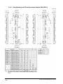
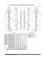
1
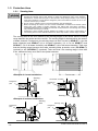
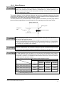
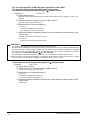
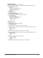
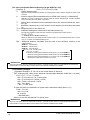
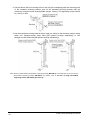
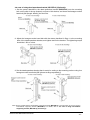
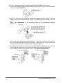
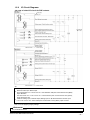
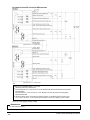
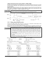
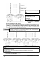
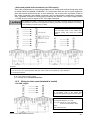
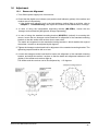
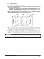
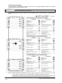
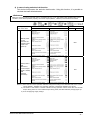
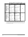
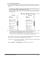
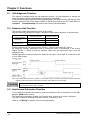
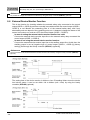
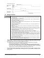
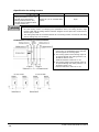
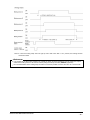
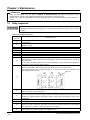
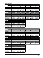
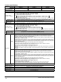
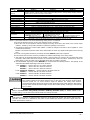
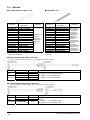
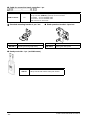
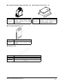
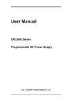
<Series and parallel mixed connection (for PNP output)>
This is the configuration for connecting multiple sets of emitter and receiver facing each other
in mixed series and parallel combination. It is used when there are two or more dangerous
parts that can be entered from two or more directions. Up to three sets of sensors in total of
the series connection and parallel connection can be connected in combination. However,
max. 192 beam channels for each series connection are allowed. The control output (OSSD
1, OSSD 2) turns only its output to OFF if the light is blocked.
For parallel connection, connect the one receiver to the other connection using the interference
prevention line as shown in the figure below. Wrong connection could generate the non-sensing
area, resulting in serious injury or death.
The sensor output is selected depending on
the connecting state of the shield wire.
Incorrect wiring may cause the lockout
state.
*Symbols
Switch S1 (Connectable either to +V or 0V)
0 to+1.5V or Vs to Vs-2.5V: Emission halt (sink current 5mA or less) (Note 2), Open: Emission
K1, K2: External device
Notes: 1) If the interference prevention wire is extended, use a φ0.2mm2, or more, shielded twisted pair cable.
2) Vs is the applying supply voltage.
3) For resetting, refer to ‘2-5 Interlock Function’.
1-5-5
Wiring for Auto-reset (Interlock is Invalid)
<For PNP output>
The sensor output is selected depending on
the connecting state of the shield wire.
Incorrect wiring may cause the lockout state.
*Symbols
Switch S1
(Connectable either to +V or 0V)
0 to+1.5V or Vs to Vs-2.5V: Emission
(source current 5mA or less)
(Note)
Open: Emission halt
Note: Vs is the applying supply voltage.
SUNX Limited MJE-SF4B No.6084-00
- 33 -