1
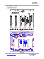
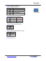
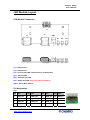
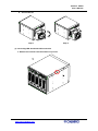
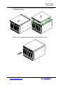
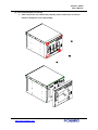
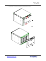
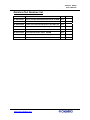
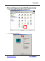
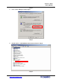
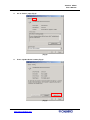
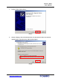
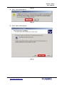
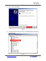
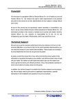
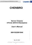
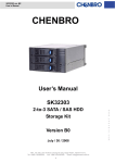
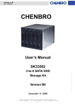
Chenbro SK235
User’s Manual
Chenbro
SK23502 / SK23512
3-to-5 SCSI Storage Kit
User’s Manual
1
http://www.chenbro.com
Chenbro SK235
User’s Manual
Copyright
This document is copyrighted, 2005, by Chenbro Micom Co., Ltd. All rights are reserved.
Chenbro Micom Co., Ltd. reserves the right to make improvements to the products
described in this manual at any time. Specifications are thus subject to change without
prior notice.
No part of this manual may be reproduced, copied, translated, or transmitted in any
form or by any means without the prior written permission of Chenbro Micom Co., Ltd.
Information provided in this manual is intended to be accurate and reliable. However,
Chenbro Micom Co., Ltd., assumes no responsibility for its use, nor for any
infringements upon the rights of third parties, which may result from its use.
Technical Support
We want you to get the maximum performance from your products. So if you run into
technical difficulties, we are here to help. For the most frequently asked questions, you
can easily find answers in your product documentation. These answers are normally a
lot more detailed than the ones we can give over the phone.
So please consult this manual first. If you still cannot find the answer, gather all the
information or questions that apply to your problem, and with the product close at hand,
call your dealer. Our dealers are well trained and ready to give you the support you
need to get the most from your Chenbro products. In fact, most problems reported are
minor and are able to be easily solved over the phone.
In addition, free technical support is available from Chenbro engineers every business
day. We are always ready to give advice on application requirements or specific
information on the installation and operation of any of our products.
Preliminary Edition Printed in Taiwan Oct 2005
2
http://www.chenbro.com
Chenbro SK235
User’s Manual
Packing List
Chenbro’s 3-to-5 storage kit SK23502/SK23512 series standard packing includes:
z
SK23502/SK23512 Storage Case
z
Ultra320 SCSI Backplane
z
SK23502/SK23512 LED board (Front)
z
USB / Serial ATA LED cable (bundled)
z
80mm (T32mm) Exhaust Fan
z
Screws: #6-32 (6mm) x 20 pcs, M3 (6mm) x 12 pcs
z
Five Drive Carriers (Black)
z
One SCSI cable
z
One extended USB cable (500mm)
z
One external SCSI terminator
Technical Specifications
Occupancy
Three 5.25” Drive Bays
Capacity
Five Ultra320 SCSI hard drives
Cooling
One 80mm (T32mm) Exhaust Fan
Subsystem
System
z
Fan Fail Detection LED and Alarm
Monitoring
z
Overheat LED and Alarm
z
Drive Fail LED and Alarm (SK23512 only)
Front Access
Two USB ports in the front panel
Dimension
146 x 128 x 220 (mm)
(WxHxD)
5.75 x 5.04 x 8.66 (inch)
Weight (include
2.2 kgs
fan)
Chassis Supported
z
RM313 / RM411 / RM412 / RM422
z
SR107 / SR108 / SR105 (exclude “Granite” series panel)
3
http://www.chenbro.com
Chenbro SK235
User’s Manual
Introduction
The Chenbro SK23502/SK23512 is design for fitting with any chassis which has three
5.25” bays (and space available for depth 9.5” as recommended), it can use this space
to turn to five hard drives integrated. For those who want the existing servers to have
more HDD density with keeping the flexibility, this storage kit is the best solution as
value add feature and excellent performance.
Functional Specification
General
z
Support Ultra320 SCSI SCA (80pin) interface
z
Support optional SAF-TE function (SK23512 only)
z
Compatible with 3.5” Ultra320 SCSI drive
Host/Drive/Power interfaces
z
5 Ultra-320 SCSI disks per backplane with 80-pin SCA2 connectors for internal
connection
z
2 HDCI SCSI in/out 68-pin connectors for backplane cascading, external device
and terminator.
z
SCSI ID is based on “group” and configured by a DIP switch without ID conflict
check
z
2-digit DIP switch to control disk spin up: AUTO, DELAY, and COMMAND
z
Individual disk activity signals per hard disk : Power LED – Blue ( When HDD is
present ), Access LED –Amber blinking (When HDD is busy )
z
2 USB access ports
z
No SCSI terminator on board (Use External Terminator)
z
2 big-4P (Molex device connector) power inlets
Monitoring Function
z
1 x Fan 3P3C connectors with speed monitoring
z
Fan monitoring can be disabled separately
z
5 x temperature sensors (facing to HDD) for overheating monitoring
z
Overheat temperature is selectable – 55 degC/65 degC
z
Support one buzzer for audible alarm, three fail LED output for fan/overheat/HDD
fail events, one alarm mute button for disabling audible alarm
z
Alarm mute & LED outputs are connected through 2 x 7 pin header (pitch=2.54)
with 1 key pin to the LED board
4
http://www.chenbro.com
Chenbro SK235
User’s Manual
Backplane Layout
Backplane Connectors
JP1
HDD5
HDD4
HDD3
HDD2
HDD1
Rear View
FAN1
CN1
JP2
CN2
SW1
CON2
CON1
Front View
5
http://www.chenbro.com
Chenbro SK235
User’s Manual
Connector Description
(1) [SCSI_HDD1/SCSI_HDD2/SCSI_HDD3/SCSI_HDD4/SCSI_HDD5] : Connect SCSI HDD
(2) [JP1] : Connect Fail LED / USB connector (to LED board)
(3) [CON1 / CON2] : Connect SCSI HBA (68-pin)
(4) [FAN1] : Fan connector
(5) [CN1 / CN2] : Power connectors
(6) [SW1] : Overheat alarm setting
(7) [JP2] : Front USB connector (to M/B)
Pin Assignment
[FAN1]
Pin
Def.
1
GND
2
+12V
3
Sensor
FAN Connector
[CN1 / CN2]
Pin
Def.
1
+5V
2
GND
3
GND
4
+12V
Power Connector
[JP1]
Pin
Def.
Pin
Def.
Pin
Def.
Pin
Def.
1
USB_Vcc
5
USB_D0+
9
USB_D1-
13
Mute(-)
2
Overheat(-)
6
G_Diskfail(-)
10
GND
14
Key pin
3
USB_D0-
7
USB_Vcc
11
USB_D1+
4
Fan_fail(-)
8
Vcc
12
GND
LED Connector
[JP2]
Pin
Def.
Pin
Def.
1
USB_Vcc
6
USB_Vcc
2
USB_D0+
7
USB_D1+
3
USB_D0-
8
USB_D1-
4
GND
9
GND
5
Key-Pin
USB Connector
N/C
6
http://www.chenbro.com
Chenbro SK235
User’s Manual
Default Jumper Setting (with “*”)
SW1[1,2]: HDD Spin-up Option
SW1-1
SW1-2
Function
Off
Off
Spin up when power is apply
Off
On
Spin up on start command
On
Off
Spin up after delay
On
On
Reserved
FAN Connector
SW1[3]: HDD ID and SAF-TE ID Setting
SW1-3
HDD ID
Chip ID
(HDD1 – HDD5)
(SK23512 Only)
Off
0–4
6
On
8 – 12
14
SW1[4]: Fan1 Monitoring Alarm Setting
Sw1-4
Fan1
On
Enable
Off
Disable
SW1[5]: Temperature Monitoring Alarm Setting
Sw1-5
Temperature
On
65 Degree C
Off
55 Degree C
SW1[6]: NC (Reserved)
7
http://www.chenbro.com
Chenbro SK235
User’s Manual
LED Module Layout
LED Module Connectors
J3
J2
J1
SW1
D1
D2
D3
[J1] : USB Port #1
[J2] : USB Port #2
[J3] : Connect Fail LED / USB connector (to backplane)
[D1] : Fan Fail LED
[D2] : Overheat Fail LED
[D3] : Global Fail LED (Only functional on SK23512)
[SW1] : Alarm Mute Switch
Pin Assignment
[J3]
Pin
Def.
Pin
Def.
Pin
Def.
Pin
Def.
1
USB_Vcc
5
USB_D0+
9
USB_D1-
13
Mute(-)
2
Overheat(-)
6
G_Diskfail(-)
10
GND
14
Key pin
3
USB_D0-
7
USB_Vcc
11
USB_D1+
4
Fan_fail(-)
8
Vcc
12
GND
8
http://www.chenbro.com
LED Connector
Chenbro SK235
User’s Manual
Installation Procedures
Please follow below sessions of different installation procedures for HDD assembly,
backplane assembly and some proper usage information.
(1) Assembly hot-swappable hard drives
a. Push the blue latch of hard drive carrier and pull the carrier out from the case
b. Attach the hard drives with six screws / per carrier
Step-1
Step-2
9
http://www.chenbro.com
Chenbro SK235
User’s Manual
c. Insert the hard drive assembly to the tray
(2) Accessing the exhaust fan
a. Push the tab on the right side (where have “push” mark on the fan cover)
10
http://www.chenbro.com
Chenbro SK235
User’s Manual
b. Pull out the fan
Step-1
Step-2
(3) Accessing LED board and USB connection
a. Release two screws from both sides of top cover
11
http://www.chenbro.com
Chenbro SK235
User’s Manual
b. Slide forwards the top cover and remove the top cover, and you can see the LED
board and LED cable
c. User can directly plug the USB connector to the USB port as below.
12
http://www.chenbro.com
Chenbro SK235
User’s Manual
(4) Accessing backplane assembly
a. After remove the rear exhaust fan (step #2), please release four screws (as
below) to backplane cover disassembly
13
http://www.chenbro.com
Chenbro SK235
User’s Manual
b. Remove two screws on the center-top and bottom as below.
14
http://www.chenbro.com
Chenbro SK235
User’s Manual
Relative Part Number List
Part No.
Description
Unit
83-305335-001
80mm T32 FAN,SK33502,W/HOLDER & SCREW
Pcs
80-035335-001
SK235/335 LED board
Pcs
80-105235-002
SK235 Ultra 320 SCSI Backplane (Non SAF-TE)
Pcs
80-105235-001
SK235 Ultra 320 SCSI Backplane (w/ SAF-TE)
Pcs
26-033219-002
USB Cable 2.0, 750mm, Universal Specification
Pcs
26-073214-003
Ultra 320 SCSI Cable, 68pin, 500MM
Pcs
26-033219-002
USB Cable 2.0, 750mm, Universal Specification
Pcs
31-040000-006
Ultra 320 SCSI External Terminator
Pcs
15
http://www.chenbro.com
Remark
Chenbro SK235
User’s Manual
Driver installing process (for SAF-TE support only)
1.
Open “Control Panel” and double click on “System” (Fig.1)
(Fig.1)
2.
Go to “Hardware” page (Fig.2)
16
http://www.chenbro.com
Chenbro SK235
User’s Manual
(Fig.2)
3.
Press “Device Manger” button (Fig.3)
(Fig.3)
4.
Double click on “SDR GEM318 SCSI Processor Device” (Fig.4)
(Fig.4)
17
http://www.chenbro.com
Chenbro SK235
User’s Manual
5.
Go to “Driver” page (Fig.5)
(Fig.5)
6.
Press “Update Driver” button (Fig.6)
(Fig.6)
18
http://www.chenbro.com
Chenbro SK235
User’s Manual
7.
Click on “Next” button (Fig.7)
(Fig.7)
8.
Choose “Display a list of the known drivers for this device so that I can choose a
specific driver” item then press ”Next” button (Fig.8)
(Fig.8)
19
http://www.chenbro.com
Chenbro SK235
User’s Manual
9.
Choose “System devices” item then press “Next” button (Fig.9)
(Fig.9)
10.
Choose “HP” item in left window and “HP SAFETE SCSI Processor Device” item in
right window then press “Next” button (Fig.10)
20
http://www.chenbro.com
Chenbro SK235
User’s Manual
(Fig.10)
11.
Press “Yes” button (Fig.11)
(Fig.11)
12.
Press “Next” button (Fig.12)
(Fig.12)
21
http://www.chenbro.com
Chenbro SK235
User’s Manual
13.
Press “Finish” button (Fig.13)
(Fig.13)
14.
Please check System devices which shows “HP SATETE SCSI Processor Device”
including (Fig.14)
(Fig.14)
22
http://www.chenbro.com
Chenbro SK235
User’s Manual
23
http://www.chenbro.com