1
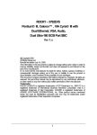
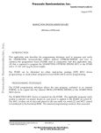
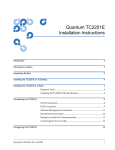
M68HC705E24PGMR/D
Rev. 2
March 1995
M68HC705E24PGMR
PROGRAMMER
USER'S MANUAL
Third Edition
© MOTOROLA Ltd., 1993, 1995; All Rights Reserved
Motorola reserves the right to make changes without further notice to any products herein to
improve reliability, function, or design. Motorola does not assume any liability arising out of the
application or use of any product or circuit described herein; neither does it convey any license under
its patent rights nor the rights of others. Motorola products are not designed, intended, or
authorized for use as components in systems intended for surgical implant into the body, or other
application in which the failure of the Motorola product could create a situation where personal
injury or death may occur. Should Buyer purchase or use Motorola products for any such
unintended or unauthorized application, Buyer shall indemnify and hold Motorola and its officers,
employees, subsidiaries, affiliates, and distributors harmless against all claims, costs, damages, and
expenses, and reasonable attorney fees arising out of, directly or indirectly, any claim of personal
injury or death associated with such unintended or unauthorized use, even if such claim alleges that
Motorola was negligent regarding the design or manufacture of the part.
Motorola and the Motorola logo are registered trademarks of Motorola Inc.
Motorola Inc. is an Equal Opportunity/Affirmative Action Employer.
1. INTRODUCTION............................................................................................1-5
2. PROGRAMMING TECHNIQUE..........................................................................2-6
2.1 PARALLEL MODE............................................................................................................................2-6
2.1.1 Programming the MCU PROM (PARALLEL)..................................................................................2-6
2.1.2 Verify MCU PROM (PARALLEL).................................................................................................2-7
2.1.3 Blank Verify MCU PROM (PARALLEL)........................................................................................2-8
2.2 SERIAL MODE............................................................................................2-8
3. PROGRAMMER PREPARATION........................................................................3-9
3.1
3.2
3.3
3.4
EXTERNAL POWER SOURCE...........................................................................................................3-9
EPROM INSTALLATION...................................................................................................................3-9
PROGRAMMING OPERATION.........................................................................................................3-10
VERIFY OPERATION.......................................................................................................................3-10
This page intentionally left blank
CHAPTER1.
INTRODUCTION
This manual describes the technique used to program and verify the MC68HC705E24
microcontroller (MCU) internal OTPROM/EPROM. All that is required to program the
MC68HC705E24 OTPROM/EPROM MCU is the PGMR and a +5 volt and VPP dc power
supply.
The PGMR supports 64 pin Quad Flat Pack (QFP) MCU, 44 Quad Flat Pack (QFP and 68 pin
Plastic Leaded Chip Carrier (PLCC) MCU device programming.
NOTE: 68pin PLCC MCU is inserted in a dead bug fashion (i.e. upside down).
CHAPTER 2.
PROGRAMMING TECHNIQUE
2.1 PARALLEL MODE
The parallel PGMR programming technique allows the user program, contained in an external
EPROM, to be copied into the internal PROM (OTPROM/EPROM) of the MC68HC705E24
MCU device. This mode is selected by setting JP1 to the LOOP position and JP2 to the
PARALLEL position.
1
(2)
(3)
JP1
NO LOOP
FABRICATED
JUMPER
1
(2)
LOOP
(3)
JP2
PARALLEL
SERIAL
The MC68HC705E24 MCU device is inserted the appropriate socket on the PGMR . The
applicable program/verify routine is selected via the switch pack S3 , and power is applied to the
PGMR via switch S1. The MCU is taken out of reset and placed in the run mode via switch S2, and
MCU control is transferred to the bootstrap ROM. The selected programming routine is then
executed.
NOTE
Only a single E24 MCU may be installed in the PGMR board at any time.
2.1.1 Programming the MCU PROM (PARALLEL)
To select the program mode the switch pack S3 should both be set to 08 hex (PD7-PD0) (open
switches correspond to a high PD bit).
Open
S3
Closed
7 6 5 4 3 2 1 0
In the program MCU PROM routine, the contents of an external 32K EPROM are copied into the
MCU PROM areas of the applicable device. There is a direct correlation of addresses between the
two devices. Non-MCU PROM addresses are ignored so data contained in those areas are not
accessed. Unprogrammed external EPROM address locations should contain $00 to speed up the
programming operation. During the programming routine, the PROGRAM LED D2 is illuminated.
At the end of the programming routine, D2 is turned off, and the verification routine is entered. If
the contents of the MCU PROM and external EPROM exactly match, then the VERIFY LED D3 is
illuminated.
During the verification routine, all locations are compared to the data residing in external EPROM.
The verification routine will stop if a discrepancy has been detected and the error address location
will be placed on the external memory address bus.
2.1.2 Verify MCU PROM (PARALLEL)
To select the verify mode switch pack S3 should be set to 09 hex (PD7-PD0) (open switches
correspond to a high PD bit). The verify MCU PROM contents routine is normally entered
automatically after the MCU PROM is programmed. Direct entry of this mode will cause the MCU
PROM contents to be compared to external EPROM contents residing at the same address locations.
Both D2 and D3 LEDs are turned off at this time until verification is completed. Upon completion
of the verification routine (every location verified) the VERIFIED LED D3 is illuminated. If D3 does
not illuminate, a discrepancy has been detected and the error address location will be placed on the
external memory address bus.
2.1.3 Blank Verify MCU PROM (PARALLEL)
To select the blank verify mode switch pack S3 should be set to 0B hex (PD7-PD0) (open switches
correspond to a high PD bit).
Open
S3
Closed
7 6 5 4 3 2 1 0
The blank verify mode will cause the MCU PROM to be checked against the erased state. Both D2
and D3 LEDs are turned off at this time until verification is completed. Upon completion of the
verification routine (every location verified erased) the VERIFIED LED D3 is illuminated. If D3
does not illuminate, a discrepancy has been detected and the error address location will be placed on
the external memory address bus.
2.2 SERIAL MODE
This mode is selected by setting jumper JP1 to the SERIAL position.
1
(2)
(3)
JP1
NO LOOP
FABRICATED
JUMPER
1
(2)
LOOP
(3)
JP2
PARALLEL
SERIAL
The serial mode allows communication with the device using the Load RAM and Execute software.
The PGMR kit comes with a software program that allows programming of the E24 MCU via a
serial link. To use the serial software connect the PGMR board to your computer and execute the
E24EVS2 program. Follow the on-screen instructions to program the MCU.
CHAPTER 3.
PROGRAMMER PREPARATION
The PGMR must be prepared/configured prior to any program/verify operations. Board preparation
consists of the external power source (+5V and VPP ), EPROM installation, QFP or PLCC PGMR
configuration.
3.1 EXTERNAL POWER SOURCE
Power connector P1 is used to connect an external power supply to the PGMR. A +5 Vdc @ 100
mA power source is connected to connector P1 pins labeled +5V and GND. The programming
voltage power source is connected to pins labeled VPP and GND. Refer to the specific device data
sheet for programming voltage (VPP ) specifications.
NOTE
The programming voltage (VPP ) must be measured at C5 +ve terminal during
programming cycle (D2) PROGRAM LED illuminated.
3.2 EPROM INSTALLATION
The basic EPROM device used on the PGMR (at location SKT1) is a 27256 or 27C256, 32K
EPROM, 28-pin device. This EPROM device contains the user code to be programmed into the
applicable PROM MCU device.
3.3 PROGRAMMING OPERATION (PARALLEL METHOD)
To program the MC68HC705E24 MCU PROM, perform the following steps:
1. Place switch S1 to POWER-OFF (left) position.
2. Install MCU and EPROM devices into PGMR.
NOTE: 68 pin PLCC MCU is inserted in a dead bug fashion (i.e. upside down)
3. Place switch S2 to RESET-IN (left) position.
4. Check that the following are set :
JP1 - LOOP position
JP2 - PARALLEL position
S3 - PD0 closed PD1 closed PD2 closed PD3 open
PD4 closed PD5 closed PD6 closed PD7 closed
5. Place switch S1 to POWER-ON (right) position.
6. Place switch S2 to RESET-OUT (right) position.
RED LED illuminates signifying programming sequence being performed.
GREEN LED illuminates signifying verification is completed.
7. Place switch S2 to RESET-IN (left) position.
8. Remove power (via S1), or select and run new routine.
3.4 VERIFY OPERATION (PARALLEL METHOD)
To verify the MC68HC705E24 MCU PROM, perform the following steps:
1. Place switch S1 to POWER-OFF (left) position.
2. Install MCU and EPROM devices into PGMR.
NOTE: 68 pin PLCC MCU is inserted in a dead bug fashion (i.e. upside down)
3. Place switch S2 to RESET-IN (left) position.
4. Check that the following are set :
JP1 - LOOP position
JP2 - PARALLEL position
S3 - PD0 open PD1 closed PD2 closed PD3 open
PD4 closed PD5 closed PD6 closed PD7 closed
5. Place switch S1 to POWER-ON (right) position.
6. Place switch S2 to RESET-OUT (right) position.
VERIFY LED illuminates signifying verification is completed.
7. Place switch S2 to RESET-IN (left) position.
8. Remove power (via S1), or select and run new routine.
This page intentionally left blank