1
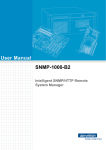
ACP-5260
5U-High Rackmount
Industrial Computer Chassis
with SCSI Ultra320 Mobile
HDD Trays
User’s Manual
Copyright
This documentation and the software included with this product have
been copyrighted by Advantech Co., Ltd. in April, 2005. All rights are
reserved. Advantech Co., Ltd. reserves the right to make improvements in
the products described in this manual at any time without notice.
No part of this manual may be reproduced, copied, translated or transmitted in any form or by any means without the prior written permission of
Advantech Co., Ltd. Information provided in this manual is intended to
be accurate and reliable. However, Advantech Co., Ltd. assumes no
responsibility for its use, or for any infringements of the rights of third
parties which may result from its use.
Acknowledgements
Intel®, Pentium® 4, and Celeron® are trademarks of Intel Corporation.
The ACP-5260, PCA-6120, PCA-6120P4, PCA-6120P12, PCA6120P18, PCA-6119P7, PCA-6119P16 and PCA-6119P17 are trademarks of Advantech Co., Ltd. All other product names or trademarks are
the properties of their respective owners.
On-line Technical Support
For technical support and service, please visit our support website at:
http://www.advantech.com/support
Part No. 2002526001
ACP-5260 User’s Manual
2nd Edition
April, 2005
ii
FCC
This device complies with the requirements in
part 15 of the FCC rules: Operation is subject to
the following two conditions:
1.This device may not cause harmful interference, and
2.This device must accept any interference
received, including interference that may cause
undesired operation
This equipment has been tested and found to
comply with the limits for a Class A digital device,
pursuant to Part 15 of the FCC Rules. These limits are designed to provide reasonable protection
against harmful interference when the equipment
is operated in a commercial environment. This
equipment generates, uses, and can radiate
radio frequency energy and, if not installed and
used in accordance with the instruction manual,
may cause harmful
interference to radio communications. Operation
of this device in a residential area is likely to
cause harmful interference in which case the
user will be required to correct the interference at
his/her own expense. The user is advised that
any equipment changes or modifications not
expressly approved by the party responsible for
compliance would void the compliance to FCC
regulations and therefore, the user's authority to
operate the equipment.
iii
A Message to the Customer
Advantech customer services
Each and every Advantech product is built to the most exacting specifications to ensure reliable performance in the harsh and demanding conditions typical of industrial environments. Whether your new Advantech
equipment is destined for the laboratory or the factory floor, you can be
assured that your product will provide the reliability and ease of operation
for which the name Advantech has come to be known. Your satisfaction
is our primary concern. Here is a guide to Advantech’s customer services.
To ensure you get the full benefit of our services, please follow the
instructions below carefully.
Technical support
We want you to get the best performance possible from your products. If
you run into technical difficulties, we are here to help. For the most frequently asked questions, you can easily find answers in your product documentation. These answers are normally a lot more detailed than the ones
we can give over the phone.
Please consult this manual first. If you still cannot find the answer, gather
all the information or questions that apply to your problem, and with the
product close at hand, call your dealer. Our dealers are well trained and
ready to give you the support you need to get the most from your Advantech products. In fact, most problems reported are minor and can be easily
solved over the phone.
In addition, free technical support is available from Advantech engineers
every business day. We are always ready to give advice about application
requirements or specific information on the installation and operation of
any of our products.
ACP-5260 User’s Manual
iv
Product warranty
Advantech warrants to you, the original purchaser, that each of its products will be free from defects in materials and workmanship for two years
from the date of purchase.
This warranty does not apply to any products which have been repaired or
altered by persons other than repair personnel authorized by Advantech,
or which have been subject to misuse, abuse, accident or improper installation. Advantech assumes no liability under the terms of this warranty as
a consequence of such events.
If an Advantech product is defective, it will be repaired or replaced at no
charge during the warranty period. For out-of-warranty repairs, you will
be billed according to the cost of replacement materials, service time and
freight. Please consult your dealer for more details.
If you think you have a defective product, follow these steps:
Step 1. Collect all the information about the problem encountered, for
example, type of PC, CPU speed, Advantech products used,
other hardware and software used, etc. Note anything abnormal
and list any on-screen messages you get when the problem
occurs.
Step 2. Call your dealer and describe the problem. Please have your manual, product, and any helpful information readily available.
Step 3. If your product is diagnosed as defective, obtain an RMA (return
material authorization) number from your dealer. This allows us
to process your return more quickly.
Step 4. Carefully pack the defective product, a fully-completed Repairand Replacement Order Card and a photocopy proof of purchase
date (such as your sales receipt) in a shippable container. A product returned without proof of the purchase date is not eligible for
warranty service.
Step 5. Write the RMA number visibly on the outside of the package and
ship it prepaid to your dealer.
v
Initial Inspection
Before you install your backplane, please make sure that the following
materials have been shipped:
• ACP-5260 Chassis
• User’s Manual
• Warranty Card
• Accessory box with a package of screws (4 screws for fastening the
slim type CD-ROM drive, 12 screws for fastening the disk drives, 6
screws for fixing the ear handles), a 68-pin SCSI flat cable, a small
interface converter for slim type CD-ROM drive, a pair of keys, 20
rubber cushions, a pair of ear handles, a big-to-small 4-pin power wire,
and a spare filter.
If any of these items are missing or damaged, contact your distributor or
sales representative immediately. We have carefully inspected the ACP5260 mechanically and electrically before shipment. It should be free of
marks and scratches and in perfect working order upon receipt. As you
unpack the ACP-5260, check it for signs of shipping damage. (For example, damaged box, scratches, dents, etc.) If it is damaged or it fails to meet
the specifications, notify our service department or your local sales representative immediately. Also, please notify the carrier. Retain the shipping
carton and packing material for inspection by the carrier. After inspection, we will make arrangements to repair or replace the unit.
ACP-5260 User’s Manual
vi
Contents
Chapter
1 General Information ........................................2
1.1
1.2
1.3
Introduction ....................................................................... 2
Specifications .................................................................... 2
Power Supply Options....................................................... 3
1.4
Environment Specifications .............................................. 4
1.5
Dimension Diagram .......................................................... 4
1.6
Safety Precautions ............................................................. 5
Table 1.1:Power supply options...................................... 3
Table 1.2:Environment specifications ............................ 4
Figure 1.1:Dimension diagram ....................................... 4
Chapter
2 System Setup.....................................................8
2.1
Chassis front and rear section............................................ 8
2.1.1
2.1.2
2.1.3
2.2
The front section includes:.............................................. 8
Figure 2.1:Front section.................................................. 9
The rear panel includes:.................................................. 9
The rear panel ................................................................. 9
Figure 2.2:Rear panel of backplane version ................. 10
Figure 2.3:Rear panel of motherboard version ............. 10
Removing the chassis covers........................................... 11
Figure 2.4a: Removing the top front chassis cover ...... 11
Figure 2.4b:Removing the top rear chassis cover......... 11
2.3
Installing the Backplane .................................................. 12
2.4
Installing CPU Card & Add-on Cards............................. 13
2.5
Hold-down clamp............................................................ 15
2.6
Installing Disk Drives...................................................... 16
Figure 2.5:Installing the backplane............................... 12
Figure 2.6:Installing a full-length card ......................... 14
Figure 2.7: Installing hold-down clamp........................ 15
Figure 2.8: Installing IDE Disk Drives......................... 17
Chapter
3 Operation ........................................................20
3.1
The Front Panel of ACP-5260......................................... 20
3.1.1
3.1.2
3.1.3
3.2
Switch, Buttons and I/O Interfaces ............................... 20
LED indicators for System Status................................. 20
Figure 3.1:Front LED panel.......................................... 20
Table 3.1:LED indicators for System Status ................ 21
LED indicators for Power Status .................................. 21
Table 3.2:LED indicators for Power Status .................. 21
Replacing the Cooling Fan.............................................. 22
3.2.1
Replacing the high-speed cooling fan........................... 22
Figure 3.2: Replacing the cooling fan........................... 22
vii
Table of Contents
3.2.2
3.2.3
3.3
Replacing the Filter ......................................................... 27
3.3.1
3.3.2
3.4
Replacing the rear blower ............................................. 23
Figure 3.3: Screws and tie mount location ................... 23
Figure 3.4:Removing the blower unit ........................... 24
Figure 3.5:Both sides of the blower unit....................... 24
Replacing the fan behind the SCSI backplane.............. 25
Figure 3.6:Remove the two high-speed cooling fans ... 25
Figure 3.7:Lift the tab on top of the fan unit ................ 26
Figure 3.8:Replacing the fan behind the backplane...... 26
Replacing the front door filter ...................................... 27
Figure 3.9: Replacing the front door filter.................... 27
Replacing the side filter ................................................ 27
Figure 3.10: Replacing the side filter............................ 28
Replacing the power supply ............................................ 28
Figure 3.11: Module for 460W power supply .............. 28
Figure 3.12: Module for 570W/810W power supply ... 29
Figure 3.13: Orientation of power cord plugs............... 29
Chapter
4 Alarm Board ...................................................32
4.1
Alarm Board Layout........................................................ 32
4.2
Alarm Board Specifications ............................................ 33
4.3
Switch Settings................................................................ 35
4.4
Thermal Sensor ............................................................... 35
Figure 4.1:Alarm board layout...................................... 32
Table 4.1:Pin Definitions.............................................. 33
Table 4.2:Fan switch settings........................................ 35
Figure 4.2:Thermal sensor module ............................... 36
Table 4.3: Temperature Sensor Connectors.................. 36
Table 4.4:Thermal switch setting.................................. 37
Chapter
5 SCSI Storage and RAID ................................40
5.1
6-slot SCSI SCA Backplane............................................ 40
5.1.1
5.1.2
SCSI Backplane Layout
......................................... 40
Figure 5.1: Front side layout of the SCSI backplane.... 40
Figure 5.2: Back side layout of the SCSI backplane .... 40
Connectors and Jumpers ............................................... 41
Table 5.1:Connectors .................................................... 41
Table 5.2:Jumpers......................................................... 41
5.2
SCSI Disk Drive Housing ............................................... 42
5.3
Wires & Cables for SCSI Storage ................................... 43
5.4
Installing a SCSI HDD.................................................... 44
Figure 5.3: SCSI disk drive housing............................. 42
Figure 5.4:Wires and Cables for SCSI housing............ 43
5.4.1
ACP-5260 User’s Manual
Installing a SCSI HDD ................................................. 44
Figure 5.5:Pushing up the latch .................................... 44
Figure 5.6:Removing the mobile tray ........................... 45
viii
5.4.2
5.5
5.6
Figure 5.7:Installing a SCSI SCA 80-pin disk drive .... 45
Installing the GEM318 Driver ...................................... 46
SAF-TE ........................................................................... 47
RAID Application ........................................................... 48
Table 5.3:LED for SCSI HDD power and status.......... 48
Appendix A Exploded Diagram and Parts List ................50
Figure A.1: Exploded diagram...................................... 50
Table A.1:Parts list ....................................................... 51
Appendix B Optional Backplanes and Motherboards .....54
B.1
Backplane Options .......................................................... 54
B.2
Motherboard Options ...................................................... 55
Table B.1:Backplane options........................................ 54
Table B.2:Motherboard options.................................... 55
Appendix C Safety Instructions .........................................58
C.1
C.2
English............................................................................. 58
German – Wichtige Sicherheishinweise ......................... 60
ix
Table of Contents
ACP-5260 User’s Manual
x
CHAPTER
1
General Information
Chapter 1 General Information
1.1 Introduction
ACP-5260 is a 5U-high rackmount industrial computer chassis for highperformance and high-capacity computing platforms. It meets a variety of
application needs for filing, printing, e-mails and webserving. This powerful computing server includes full disk array storage for minimizing the
system downtime, especially in mission-critical computer telephony
applications, industrial automation, and factory management. A wide
range of standard computing peripherals can be integrated with the chassis to meet different application needs for operation under harsh conditions 24 hours a day, 7 days a week.
1.2 Specifications
• Construction: Heavy-duty steel
• Disk Drive Capacity: One slim-type CD-ROM drive bay, one 5.25”
disk drive bay, and one 3.5" disk drive bay
• RAID Storage: Supports six 3.5" SCSI SCA 80-pin hot-swappable
HDDs. Each mobile tray has a latch for protection and a pair of LEDs
for displaying the HDD power and HDD activity status.
• Security Protection: The RAID storage system, power switch and system reset button are all behind the lockable door.
• LED Indicators on Front Panel: Bi-color LEDs (green/red) for Power,
Temperature, and Fan status; single-color LEDs (green) for HDD
activity and Power Singles Status (+3.3 V, +5 V, +12 V, -5 V and -12
V). For the SCSI storage, each mobile tray has a single-color LED
(green) that displays HDD power and a bi-color LED (blue/red) that
displays HDD status.
• Switch and Buttons on Front Panel: Power switch, System Reset button
and Alarm Reset button.
• Front I/O Interfaces: Dual USB and one PS/2 keyboard connector
• Cooling System: Three 12 cm x 12 cm x 2.54 cm (114 CFM) hot-swappable cooling fans in the middle; two 8 cm x 8 cm x 2.54 cm (47 CFM)
fan behind the SCSI backplane; two adjustable blowers (25 CFM) on
the rear section.
ACP-5260 User’s Manual
2
• Air Filters: Two filters behind the front door, one 155 mm x 100 mm,
and one 176 mm x 142 mm; one filter (170 mm x 42 mm) on the inside
of the right plate.
• Vents: On the front panel and right side of the chassis
• Slide Rails: General Device C-300 series supported
• Weight: 30 kg (66 lbs)
• Dimensions (W x H x D): 482 x 222 x 660 mm (19" x 8.75" x 26")
• Chassis Color: Black
1.3 Power Supply Options
Table 1.1: Power supply options
Model
Name
1757946005 (BP)/
1757946006 (MB)
1757000129 (BP)/
1757000150 (MB)
1757000130 (BP)/
1757000151 (MB)
Watt
460 W (ATX, PFC)
(1+1 redundant)
570 W (ATX, PFC)
(2+1 redundant)
810 W (ATX, PFC)
(3+1 redundant)
Input
rating
100 ~ 240 Vac
(Full range)
115 ~ 230 Vac
(Full range)
115 ~ 230 Vac
(Full range)
Output
voltage
+5 V @ 40 A,
+3.3 V @ 30 A,
+12 V @ 27 A,
-5 V @ 0.8 A,
-12 V @ 1 A,
+5 VSB @ 2 A
+5 V @ 50 A,
+3.3 V @ 40 A,
+12 V @ 34 A,
-5 V @ 1 A,
-12 V @ 1 A,
+5 VSB @ 1.2 A
+5 V @ 75 A,
+3.3 V @ 60 A,
+12 V @ 51 A,
-5 V @ 1.5 A,
-12 V @ 1.5 A,
+5 VSB @ 1.6 A
Minimum
load
+5 V @ 5 A,
+3.3 V @ 1 A,
+12 V @ 2.5 A,
+5 VSB @ 0.1 A
+5 V @ 6 A,
+3.3 V @ 2 A,
+12 V @ 3 A,
-12 V @ 0.1 A,
-5 V @ 0.1 A,
+5 VSB @ 0.1 A
+5 V @ 9 A,
+3.3 V @ 3 A,
+12 V @ 4.5 A,
-12 V @ 0.15 A,
-5 V @ 0.15 A,
+5 VSB @ 0.15 A
MTBF
100,000 hours
@ 25° C
100,000 hours
@ 25°C
100,000 hours
@25°
Safety
UL/TUV/CB
UL/cUL/CB
UL/cUL/CB
3
Chapter 1
1.4 Environment Specifications
Table 1.2: Environment specifications
Environment
Operating
Non-operating
Temperature
0 to 40°C (32 to
104°F)
-20 to 60°C (-4 to
140°F)
Humidity
10 to 85% @ 40°C,
non-condensing
10 to 95% @ 40°C,
non-condensing
Vibration
1G rms
2G
Shock
10G with 11 ms duration, half sine wave
30G
Altitude
0 to 3,048 m (0 ~ 10,000 ft)
Safety
CE compliant, UL/cUL approved
1.5 Dimension Diagram
unit: mm
Figure 1.1: Dimension diagram
ACP-5260 User’s Manual
4
1.6 Safety Precautions
Warning!
Always completely disconnect the power cord
from your chassis whenever you work with the
hardware. Do not make connections while the
power is on. Sensitive electronic components
can be damaged by sudden power surges. Only
experienced electronics personnel should open
the PC chassis.
Caution!
Always ground yourself to remove any static
charge before touching the motherboard, backplane, or add-on cards. Modern electronic
devices are very sensitive to static electric
charges. As a safety precaution, use a grounding
wrist strap at all times. Place all electronic components on a static-dissipative surface or in a
static-shielded bag when they are not in the
chassis.
5
Chapter 1
ACP-5260 User’s Manual
6
CHAPTER
2
System Setup
Chapter 2 System Setup
The following procedures instruct users to install the backplane, add-on
cards, and disk drives into the ACP-5260 chassis. Please refer to Appendix A, Exploded Diagram, for all the detailed parts names of ACP-5260.
Note:
Use caution when installing or operating the
components with the chassis open. Be sure to
turn off the power, unplug the power cord and
ground yourself by touching the metal chassis
before you handle any components inside the
machine.
2.1 Chassis front and rear section
The ACP-5260 is composed of two sections, the front section and the rear
section. Each of them has its own top cover.
2.1.1 The front section includes:
1.
A SCSI disk drive housing with six mobile HDD trays on the front
left. For IDE devices, there are one slim-type CD-ROM drive and
one 5.25” disk drive bay are above the SCSI mobile trays, and one
3.5” disk drive bay at the right of the SCSI mobile trays.
2.
Dual cooling fans behind the SCSI backplane for cooling the SCSI
HDDs.
3.
Front door with LED panel and user-friendly rotary lock. User can
close the door with or without the key.
4.
Hot-swappable redundant power supply.
5.
A pair of ear handles which users can simply fasten to the frontright and front-left edges of the chassis with the six screws provided.
6.
Filters located behind the front door and right side of the chassis.
ACP-5260 User’s Manual
8
Figure 2.1: Front section
2.1.2 The rear panel includes:
1.
Three high-speed cooling fans in the middle, and two blowers on
the rear side
2.
Backplane
3.
Add-on cards
4.
Thermal sensor
5.
Alarm board
6.
Hold-down clamp and blower brackets
2.1.3 The rear panel
There are two reserved 9-pin D-SUB openings and dual AC inlets on the
rear panel. For B/P version, it includes the B/P rear plate with 20-slot I/O
brackets (Figure 2.2). For M/B version, it includes the M/B rear plate
with 7-slot I/O brackets and the ATX M/B I/O cover (Figure 2.3).
9
Chapter 2
Figure 2.2: Rear panel of backplane version
Figure 2.3: Rear panel of motherboard version
ACP-5260 User’s Manual
10
2.2 Removing the chassis covers
There are dual top covers for ACP-5260, top front cover and top rear
cover. Both are fixed to the chassis with four screws, two on each side.
Please refer to Figure 2.4a & Figure 2.4b and proceed as follows.
1.
Detach the four screws on both sides.
2.
Remove the top cover.
Figure 2.4a: Removing the top front chassis cover
Figure 2.4b: Removing the top rear chassis cover
11
Chapter 2
2.3 Installing the Backplane
ACP-5260 supports backplanes of up to 20 slots. To install the backplane,
please refer to Figure 2.5 and proceed as follows:
1.
Remove the top rear chassis cover, and then dismantle the holddown clamp and the blower units by removing the four screws.
2.
Put the backplane in the proper location and then fasten it onto the
chassis.
3.
Connect the 20-pin ATX power connector from the power supply to
the backplane.
4.
Replace the hold-down clamp and the blower units, and fasten them
to the chassis.
5.
Return the top rear chassis cover and fasten it.
Figure 2.5: Installing the backplane
ACP-5260 User’s Manual
12
2.4 Installing CPU Card & Add-on Cards
ACP-5260 supports up to 20 add-on cards. To install a CPU card or addon card, please proceed as follows:
1.
Remove the top rear chassis cover, and then dismantle the holddown clamp and the blower units by removing the four screws.
2.
Select a vacant PICMG slot for the full-length CPU card, or a PCI/
ISA slot for other add-on cards. Then, remove the corresponding I/
O bracket attached to the rear plate of the chassis.
3.
Insert the CPU card or add-on card vertically into the proper slot
(See Figure 2.6). For full-length cards, please make sure that the
card bracket has been inserted properly and the other edge of the
card has been inserted into the plastic guiding fillister. Fasten the
card with the screw on top of the I/O bracket.
4.
Repeat Step 2 and 3 if there is more than one add-on card.
5.
There are two rows of notches on both sides of the hold-down
clamp for inserting rubber cushions into. One side is for PCI cards,
while the other side is for ISA cards. Depending on the card height,
the cushions can be inserted upward or downward. After the rubber
cushions have been inserted into the notches, they will stabilize the
add-on cards to protect them from shock and vibration.
6.
Put back the hold-down clamp and blower brackets and then screw
them in place.
7.
Replace the top rear chassis cover and fasten it.
13
Chapter 2
Figure 2.6: Installing a full-length card
ACP-5260 User’s Manual
14
2.5 Hold-down clamp
The hold-down clamp protects all the cards from vibration and shock.
After installing all the cards, re-fasten the hold-down clamp. Please refer
to the following steps.
1.
After plugging in the CPU card and add-on cards, please insert the
rubber cushions provided into the notches of the hold-down clamp,
and adjust them to the placement of the cards. The cushions offer
these cards the protection against shock and vibration.
2.
Put the hold-down clamp back into its original position.
3.
Secure the hold-down clamp to the chassis with the four screws.
Figure 2.7: Installing hold-down clamp
15
Chapter 2
2.6 Installing Disk Drives
APC-5260 supports both IDE and SCSI storage devices. We will introduce the IDE disk drive installation procedure here. For installing a SCSI
HDD, please refer to Chapter 5 for detailed SCSI information and installation procedure.
The IDE disk drive housing supports one slim type CD-ROM drive, one
5.25” and one 3.5” disk drive bay. The slim type CD-ROM drive and the
5.25” disk drive bay are located above the SCSI disk drive housing. The
3.5” disk drive bay is in the front middle section. Please follow these
steps for installation.
1.
Remove the chassis top covers.
2.
For installing the 3.5” HDD or FDD, simply release the two screws
on top of the disk drive holder located in the middle of the front
panel.
3.
Insert the disk drive into the proper location in the drive housing
and secure them with the screws provided.
4.
To install the 5.25” disk drive, you need to release the 3.5” disk
drive holder first. Then, loosen the four screws on the 5.25” disk
drive housing.
5.
Insert the disk drive in the proper location in the drive housing, and
secure it with the screws provided.
6.
To install the slim type CD-ROM drive, first find the small converter in the accessory box. Connect the converter to the rear of the
CD-ROM drive and fasten it with the two screws provided. Then
simply fix the CD-ROM drive to the drive housing with the four
screws provided.
7.
Connect a 40-pin flat cable to the CD-ROM drive (or CD-RW drive
or DVD-ROM drive or IDE HDD) or a 34-pin flat cable to a FDD.
Then plug the 4-pin power connector into the disk drive(s).
8.
Put the disk drive housing back in the correct position and fasten it
with the screws.
9.
Replace the chassis top covers and fasten it.
ACP-5260 User’s Manual
16
Figure 2.8: Installing IDE Disk Drives
17
Chapter 2
ACP-5260 User’s Manual
18
CHAPTER
3
Operation
Chapter 3 Operation
3.1 The Front Panel of ACP-5260
In the middle of the front panel, there is one Power On/Off switch, one
System Reset button, one Alarm Reset button, a dual USB port, and a PS/
2 connector. There are nine LED indicators on the lockable front door.
Their individual functions are described as below.
3.1.1 Switch, Buttons and I/O Interfaces
Momentary Power switch: Press this button to turn the system power on
or off. Please use system shutdown or press this switch for few seconds to
turn off the system ATX power.
System Reset button: Press the button to reboot the system.
Alarm Reset button: Whenever a fault occurs in the system (e.g., fan failure or the temperature in the chassis is too high), the audible alarm will be
activated. Pressing this button will stop the alarm from beeping.
Dual USB port: Connect USB devices to the system by this port.
PS/2 connector: Connect a PS/2 keyboard by this connector.
3.1.2 LED indicators for System Status
The LED display on the front door shows a series of indicators that are
grouped into two categories for System Status and Power Status.
Figure 3.1: Front LED panel
ACP-5260 User’s Manual
20
The following table describes the LED indicators for System Status.
Table 3.1: LED indicators for System Status
LED
Description
Green
Red
PWR
System Power
Normal
Abnormal
HDD
Hard Disk Drive
Activity
Data Access
No light
TEMP
Temperature in
the Chassis
Normal
Abnormal
FAN
Cooling Fan
Normal
Abnormal
When the system power is on, the PWR LED is always green.
When the PWR LED is RED, it indicates a redundant power supply module failure. To stop the alarm beep, press the Alarm Reset button. Examine the redundant power supply module right away and replace the failed
module with a good one.
When the FAN LED is RED, it indicates a failed cooling fan, and the
alarm is also activated. To stop the alarm beep, press the Alarm Reset button and then replace the failed fan with a good one immediately.
If the TEMP LED is RED, it means that the inside of the chassis is overheated. An audible alarm will be activated. To stop the alarm beep, press
the Alarm Reset button. Inspect the fan filter and the rear section of the
chassis immediately. Make sure the airflow inside the chassis is smooth
and not blocked by dust or other particles.
3.1.3 LED indicators for Power Status
The following table is the individual LED which indicates the status of
the backplane voltage signals.
Table 3.2: LED indicators for Power Status
LED
Description
LED on
LED off
+3.3V
+3.3V signal
Normal
Abnormal
+5V
+5V signal
Normal
Abnormal
+12V
+12V signal
Normal
Abnormal
-5V
-5V signal
Normal
Abnormal
-12V
-12V signal
Normal
Abnormal
21
Chapter 3
When an LED fails to light up, it means there is a problem with one of the
voltage signals. Please check if the power supply connector is properly
attached to the backplane. If the problem persists, consult with an experienced technician.
3.2 Replacing the Cooling Fan
There are seven cooling fans inside the chassis. All of the cooling fans are
easily maintained. Three of the high-speed cooling fans are located in the
middle of the chassis. There are two blowers on the rear of chassis.
Another two cooling fans are located behind the SCSI backplane which
was mentioned in Chapter 2.1.1. The fans provide the system with ample
cooling by blowing air toward the rear. To replace the cooling fans, please
proceed according to the instructions below.
3.2.1 Replacing the high-speed cooling fan
1.
Remove the top front chassis cover.
2.
Loose the two thumbscrews on top of the fan unit and then gently
pull it out. (See Figure 3.2.) It will disconnect the cooling fan
power connector.
3.
Replace the cooling fan with a new one.
4.
Fix the new cooling fan in place by tightening the thumbscrews.
5.
Replace the top front chassis cover and fasten it.
Figure 3.2: Replacing the cooling fan
ACP-5260 User’s Manual
22
3.2.2 Replacing the rear blower
1.
Remove the top rear chassis cover.
2.
Loosen the screws on the hold-down clamp, one on the rear panel,
and one on the guide rail. and on the hold down clamp. (see Figure
3.3)
3.
Unplug the blower power connector from the alarm board, and
release the blower power wire from the tie mount.
4.
Remove the blower unit, and then detach the blower from the
bracket by loosening the screws. (see Figure 3.4)
5.
Replace the failed blower with a new one. Please note that the
blower should be oriented so that the airflow is directed toward the
back of the chassis.
6.
Secure the new blower to the bracket and then fasten the blower
unit back onto the chassis. The blower unit is uniquely designed to
provide the best airflow for any card configuration. You can adjust
its position along with the length of the guide rail bracket.
7.
Plug the blower power connector to the alarm board and fix the
wire into the tie mount.
8.
Replace the top rear chassis cover and fasten it to the chassis.
tie mount
Figure 3.3: Screws and tie mount location
23
Chapter 3
Figure 3.4: Removing the blower unit
Figure 3.5: Both sides of the blower unit
ACP-5260 User’s Manual
24
3.2.3 Replacing the fan behind the SCSI backplane
1.
Remove the top front chassis cover.
2.
Remove the two high-speed cooling fans behind the SCSI disk
drive housing first so that there is enough room for your hand to
reach the fan behind the SCSI backplane.
3.
Lift the tab on top of the fan unit so that the fan detaches from the
fan enclosure. Figure 3.8 is another view to show users how to
remove the fan. By this way, you need to remove the whole SCSI
disk drive housing first. It’s not necessary to take out the SCSI
housing to replace the fan.
4.
Unplug the fan wire on the alarm board.
5.
Put a new fan into the fan enclosure carefully until it is locked by
the tab. Be sure to install it securely in the enclosure.
6.
Plug the fan wire into the fan connector on the SCSI backplane.
7.
Replace the two high-speed cooling fans and fasten them.
8.
Replace the top front chassis cover.
Figure 3.6: Remove the two high-speed cooling fans
25
Chapter 3
Figure 3.7: Lift the tab on top of the fan unit
Figure 3.8: Replacing the fan behind the backplane
ACP-5260 User’s Manual
26
3.3 Replacing the Filter
The filter functions to block dust or particles from the work environment
and to extend the longevity of the system. The filter should be replaced
periodically. There are two filters behind the front door and one filter on
right side of the chassis. To replace the filter, please proceed as follows.
3.3.1 Replacing the front door filter
1.
Open the front door.
2.
Loosen the two screws located on the filter cover.
3.
Replace the filter with a new one.
4.
Fasten the filter cover.
Figure 3.9: Replacing the front door filter
3.3.2 Replacing the side filter
1.
Open the top front cover.
2.
Find the filter cover on the right side plate and simply take out the
filter.
3.
Replace the filter with a new one.
4.
Replace the top front cover and then fasten it.
27
Chapter 3
Figure 3.10: Replacing the side filter
3.4 Replacing the power supply
ACP-5260 supports various power supply models. To replace the power
supply module, please proceed as follows.
1.
Turn off the failed power supply module.
2.
Loosen the screw on the failed module and then gently pull the
module out by the handle (see Figure 3.11 and Figure 3.12).
3.
Make sure that the new power supply module is the same rating as
the currently installed one.
4.
Slide the power supply module inward until it locks into the right
position, then tighten the screws.
5.
Return the handle to its original place.
Figure 3.11: Module for 460W power supply
ACP-5260 User’s Manual
28
Figure 3.12: Module for 570W/810W power supply
Note:
When you plug the two power cords into the
socket, please make sure they are oriented in the
same direction. (See Figures 3.13)
Figure 3.13: Orientation of power cord plugs
29
Chapter 3
ACP-5260 User’s Manual
30
CHAPTER
4
Alarm Board
Chapter 4 Alarm Board
The alarm board is located on the right side near the rear section. The
alarm board makes an audible alarm when:
a.
Any power supply module or redundant power supply fails
b.
One of the system cooling fans or blowers fai1s
c.
Internal temperature of the chassis reaches 50°C (default setting)
To stop the alarm beep, simply press the Alarm Reset button on the front
panel.
4.1 Alarm Board Layout
The layout and detailed specification of the alarm board are given below:
Figure 4.1: Alarm board layout
ACP-5260 User’s Manual
32
4.2 Alarm Board Specifications
Input Power: +5V, +12V
Input Signals:
• 7 FAN connectors
• One thermal board connector (can connect up to 8 thermal boards in
series)
• One power good input
• One alarm reset input
• One voltage signal connector (connect from backplane, includes ±12V,
±5V, +3.3V)
• One Hard Disk LED connector (connect from CPU card)
Output Signals:
• One LED board connector
• One LCM board connector
• One Buzzer output
Table 4.1: Pin Definitions
CN1: Auxiliary External Power Connector
Pin 1
+12V
Pin 3
GND
Pin 2
GND
Pin 4
+5V
CN4: Temperature Sensor (LM75) Connector
Pin 1
+5V
Pin 3
T_SDAT
Pin 2
T_SCLK
Pin 4
GND
CN13: Voltage Detection Input Connector
Pin 1
5VSB
Pin 5
+5V
Pin 2
GND
Pin 6
+3.3V
Pin 3
GND
Pin 7
-12V
Pin 4
-5V
Pin 8
+12V
33
Chapter 4
CN16: Power Good Input
Pin 1
Power Good A
Pin 2
GND
Pin 2
GND
CN17: Alarm Reset Connector
Pin 1
ALARM RESET
CN18: LED Connector
Pin 1
GND
Pin 9
Temperature
Good LED
Pin 2
Power Good +5V
Pin 10
Temperature
Fail LED
Pin 3
Power Good +12V
Pin 11
FAN Good LED
Pin 4
Power Good -5V
Pin 12
FAN Fail LED
Pin 5
Power Good -12V
Pin 13
N/A
Pin 6
HDD_1
Pin 14
Power Good
+3.3V
Pin 7
Power Good LED
Pin 15
Power Good
+5 Vsb
Pin 8
Power Fail LED
Pin 2
N/A
Pin 2
+5V
CN26: External HDD LED connector
Pin 1
HLED_ACT
J1: External Buzzer
Pin 1
Buzzer
SW1: Fan Number Select Switch
Pin 1
GND
Pin 5
GND
Pin 2
FAN_SEL1
Pin 6
FAN_SEL3
Pin 3
GND
Pin 7
GND
Pin 4
FAN_SEL2
Pin 8
RESET
ACP-5260 User’s Manual
34
4.3 Switch Settings
Table 4.2: Fan switch settings
FAN NUMBER
SW 1-1
SW 1- 2
SW 1- 3
SW 1- 4
1
OFF
OFF
ON
OFF
2
OFF
ON
OFF
OFF
3
OFF
ON
ON
OFF
4
ON
OFF
OFF
OFF
5
ON
OFF
ON
OFF
6
ON
ON
OFF
OFF
7
ON
ON
ON
OFF
4.4 Thermal Sensor
There is a thermal sensor located on the rear plate of the chassis. It is
attached to the upper left corner of the chassis back plate. Please refer to
Figure 4.2.
When the inner temperature of the chassis is too high, the thermal sensor
sends a signal to the alarm board to trigger a continuous alarm will sound.
To stop the alarm beep, press the Alarm Reset button on the front panel.
Please refer to Figure 4.2 for the thermal sensor module layout. Users can
refer to the following temperature setting by adjusting the switch.
35
Chapter 4
Figure 4.2: Thermal sensor module
Table 4.3: Temperature Sensor Connectors
CN1: Temperature Sensor Connector
Pin 1
+5V
Pin 3
T_SDAT
Pin 2
T_SCLK
Pin 4
GND
CN2: Temperature Sensor Connector
Pin 1
+5V
Pin 3
T_SDAT
Pin 2
T_SCLK
Pin 4
GND
ACP-5260 User’s Manual
36
Table 4.4: Thermal switch setting
TEMP
INDEX
SW 1 -1
SW 1 - 2
SW 1 - 3
SW 1 - 4
TEMP 1
OFF
OFF
OFF
ON
TEMP 2
OFF
OFF
ON
ON
TEMP 3
OFF
ON
OFF
ON
TEMP 4
OFF
ON
ON
ON
TEMP 5
ON
OFF
OFF
ON
TEMP 6
ON
OFF
ON
ON
TEMP 7
ON
ON
OFF
ON
TEMP 8
ON
ON
ON
ON
37
Chapter 4
ACP-5260 User’s Manual
38
CHAPTER
5
SCSI Storage and RAID
Chapter 5 SCSI Storage and RAID
There is a SCSI SCA backplane fixed behind the SCSI disk drive housing. This backplane provides six 80-pin SCSI connectors, so users can
install up to six 80-pin SCSI HDDs. Please see the relevant details below.
5.1 6-slot SCSI SCA Backplane
5.1.1 SCSI Backplane Layout
Figure 5.1: Front side layout of the SCSI backplane
Figure 5.2: Back side layout of the SCSI backplane
ACP-5260 User’s Manual
40
5.1.2 Connectors and Jumpers
Table 5.1: Connectors
CON1 ~ CON6
80-pin Ultra320 SCSI connector
CON8
68-pin Ultra320 SCSI connector
JPWR1 ~ JPWR3 4 Pin Power Connector
CN3
For SCSI HDD status alarm function: Pin 1, 3, 5, 7,
9, 11 are the status signals for HDD1 ~ HDD6; Pin
2, 4, 6, 8, 10, 12 are the alarm signals for HDD1 ~
HDD6; Pin 13 and 14 are GND
CN4 ~ CN5
Fan Connectors
LD1 ~ LD6
SCSI HDD0 ~ HDD5 power LED (green)
LED1 ~ LED6
SCSI HDD0 ~ HDD5 Bi-Color LED (blue/red): HDD
Activity: blue; HDD Fault: red; Rebuild: pink blink;
No error: slow blink (1/sec); Identification: fast blink
(~3/sec)
1
Table 5.2: Jumpers
HDD spin up options
JP1
Spin up when power is applied
Open
Open
Spin up after delay
Open
Close
Spin up on command mode
Close
Open
Reserved
Close
Close
41
JP2
Chapter 5
5.2 SCSI Disk Drive Housing
The SCSI disk drive housing is under the 5.25” IDE disk drive bay. If you
need to take out the SCSI disk drive housing from the chassis, please be
careful to release all the relevant wires/cables and fans behind the IDE
disk drive and the SCSI disk drive housing, as well as the SCSI mobile
trays first, or you may damage the system data or be difficult to take the
housing out. When in doubt, please consult with an experienced technician.
After all the relevant wires/cables, fans, and mobile trays have been disconnected, please release the four screws with the rubber cushions on the
SCSI disk drive housing, then lift it up so that you can take out the SCSI
disk drive housing.
Figure 5.3: SCSI disk drive housing
ACP-5260 User’s Manual
42
5.3 Wires & Cables for SCSI Storage
There is one 68-pin SCSI flat cable in the accessory package. This cable
is for connecting the add-on SCSI RAID card/controller and the SCSI
backplane. The power wires of the dual fans should be connected to the
alarm board. The three 4-pin power connectors on the rear side of the
SCSI backplane are for connecting the power wires from the power supply.
Note:
Please be sure to plug in these wires and cables
well before you install any SCSI HDD. When you
have to take out the SCSI disk drive housing
from the chassis, please disconnect the wires
and cables first.
Figure 5.4: Wires and Cables for SCSI housing
43
Chapter 5
5.4 Installing a SCSI HDD
5.4.1 Installing a SCSI HDD
Note:
There are various types of 3.5" SCSI HDDs on
the market. If you’re not sure which type to
choose, please consult with an experienced
technician.
Please follow the installation procedures below.
1.
Open the front door by turning the rotary lock.
2.
Push up the latch on the mobile tray (See Figure 5-4).
3.
Press down the handle of the mobile tray and pull it out as far as it
will go. Then completely take out the tray (Refer to Figure 5-5).
4.
Install a 3.5" x 1"-high SCSI SCA 80-pin HDD by fastening the
four screws.
5.
Return the mobile tray with SCSI HDD to the disk drive housing
and push it in by the handle until it is locked into the original position.
6.
Push down the latch to lock the tray into place.
Figure 5.5: Pushing up the latch
ACP-5260 User’s Manual
44
Figure 5.6: Removing the mobile tray
Figure 5.7: Installing a SCSI SCA 80-pin disk drive
45
Chapter 5
5.4.2 Installing the GEM318 Driver
The GEM318 can work well without a driver, but in order for a Windows
2000 OS to recognize it, you must install the driver. Please follow the
below steps to upload the GEM318 driver from Advantech’s website.
1.
Connect to Advantech’s eService website: http://eservice.advantech.com.tw
2.
Click on Advanced Search.
3.
Type “GEM318” under the Keyword field. Then click on
ACP-5260 User’s Manual
46
4.
The specific driver will show on the Service Request section.
5.
Click the driver, and then you will see two files. The file GEMinstall.doc is the installation guide, and the file gem318.inf is the
driver you need to install.
6.
Please be sure to follow the installation steps given in GEMinstall.doc in order to successfully complete the installation.
5.5 SAF-TE
SAF-TE stands for SCSI Accessed Fault-Tolerant Enclosure. The SCA
backplane with built-in GEM318 chipset supports SAF-TE. It provides a
standard, non-proprietary way for the third party disk and RAID controllers to be fully integrated with peripheral packing that supports status signals (LED, audible alarm, LCD, etc), hot-swap Ultra320 SCSI HDDs,
and monitoring of enclosure components, such as disk drives, power supplies, thermal sensors, fans, etc. For ACP-5260, the GEM318 chipset
checks the disk status only, for others such as fans, temperature, power
supply and voltage are monitored by an alarm board.
47
Chapter 5
5.6 RAID Application
RAID stands for Redundant Array of Independent/Inexpensive Disks.
ACP-5260 can be integrated with a SCSI RAID card, such as AMI (LSI),
Adaptec, Intel or Mylex RAID card to perform Disk Array functions. The
SCSI RAID controller is another suitable option to integrate with ACP5260.
When you install an add-on SCSI RAID card or a SCSI RAID controller
as a RAID system, please refer to the following steps.
1.
Open the top front cover and to find the 68-pin Ultra320 SCSI connector on the rear side of the SCSI backplane.
2.
Connect the provided Ultra320 SCSI 68-pin flat cable from the
SCSI backplane to the add-on SCSI RAID card or SCSI RAID controller.
3.
You can install up to six SCSI SCA-2 80-pin HDDs. Please follow
the instructions of the SCSI RAID card or SCSI RAID controller to
implement your RAID system.
Table 5.3: LED for SCSI HDD power and status
LED
Description
Green
Blue
Red
Blue &
Red
PWR
HDD
power
HDD
power on
N/A
N/A
N/A
Status
Status of
HDD
N/A
Data
access
HDD failure
Data
rebuild or
construction
ACP-5260 User’s Manual
48
Appendix
A
Exploded Diagram and
Parts List
Appendix A Exploded Diagram and
Parts List
A.1 Exploded Diagram and Parts List
Figure A.1: Exploded diagram
ACP-5260 User’s Manual
50
Table A.1: Parts list
No
Description
No
Description
1
LED Indicator Plate
27
Side Filter (170*42mm)
2
Door
28
Alarm Board (SAB-1000)
3
LED BOARD
29
Card Guide Rail
4
LED Cover
30
Rear Cover
5
Door Hinge (Right)
31
TA AWS-850
6
Filter (177*155*5mm)
32
Sensor Board (SNMP1000)
7
Door Filter Holder
33
Adapter Bracket
8
Front Panel U
34
Fan Board
9
AC 460W (1+1)
35
Card Cage U
10
Chassis U for ACP5260 A1
36
Card Guide Rail
11
Handle (Black)
37
Combo Drive Bracket
12
Rack Mount Bracket-R
38
Slim Type CD-ROM Cover
13
Side Filter Cover
39
5.25 FDD COVER
14
Side Filter
(170*42mm)
40
SCSI SCA Bay U
15
Alarm Board (SAB1000)
41
Fan (80*80*25mm)
16
Card Guide Rail
42
ASS'Y ACP KB/USB
LEFT
17
Rear Cover
43
Rack Mount Bracket-L
18
TA AWS-850
44
Rest SW Bracket
19
Sensor Board (SNMP1000)
45
System Reset Button
20
Adapter Bracket
46
Alarm Reset Button
21
Mounting Plate
47
ATX Small Switch
22
Transparent Sheet
48
Door Cover
23
Key Set for ACP-4000
49
Door Filter (155x100mm)
24
Hold Down Clamp
50
DOOR HINGE (LEFT)
25
Fan Bracket (120mm)
26
Fan Blower
51
Appendix A
ACP-5260 User’s Manual
52
Appendix
B
Optional Backplanes
and Motherboards
Appendix B Optional Backplanes and
Motherboards
B.1 Backplane Options
ACP-5260 supports a variety of backplanes. Users can contact a local
sales representative for detailed specification and information.
Table B.1: Backplane options
Model Name
Segment
Slots Per Segment
PICMG PICMG
/PCI
PCI
ISA
PCA-6120-0B1
Single
--
--
--
20
PCA-6120P4-0B1
Single
2
--
4
14
PCA-6120P12-0A1
Single
1
1
11
7
PCA-6120P18-0A1
Single
1
1
17
1
PCA-6119P7-0B1
Single
2
--
7
10
PCA-6119P16X
Single
2
--
16
1
PCA-6119P17-0B1
Single
1
1
16
--
ACP-5260 User’s Manual
54
B.2 Motherboard Options
ACP-5260 supports a variety of Advantech ATX motherboards as listed
below. You can contact a local sales representative for detailed information.
Table B.2: Motherboard options
Model Name
Bus
PCI
PCI/ISA
ISA
AGP
SATA
AIMB-740
4 (32-bit)
1
AIMB-741
4 (32-bit)
1
1
--
--
1
1 (4X)
--
AIMB-742
4 (32-bit)
1
1
1 (8X)
2
AIMB-744
2 (PCI-X 64-bit)
4 (PCI 32-bit)
--
--
1 (8X)
2
AIMB-750
2 (PCI-X 64-bit)
4 (PCI 32-bit)
--
--
1 (4X)
2
AIMB-760
1 (PCIe 16X)
2 (PCIe 1X)
5 (PCI 32-bit)
--
--
--
4
55
Appendix B
ACP-5260 User’s Manual
56
Appendix
C
Safety Instructions
Appendix C Safety Instructions
C.1 English
1.
Read these safety instructions carefully.
2.
Keep this installation reference guide for later reference.
3.
Disconnect this equipment from any AC outlet before cleaning. Do
not use liquid or spray detergents for cleaning. Use a damp cloth.
4.
For pluggable equipment, the power outlet must be installed near
the equipment and must be easily accessible.
5.
Keep this equipment away from humidity.
6.
Put this equipment on a reliable surface during installation. Dropping it or letting it fall could cause damage.
7.
The openings on the enclosure are for air convection. Protect the
equipment from overheating. DO NOT COVER THE OPENINGS.
8.
Make sure the voltage of the power source is correct before connecting the equipment to the power outlet.
9.
Position the power cord so that people cannot step on it. Do not
place anything over the power cord.
10.
All cautions and warnings on the equipment should be noted.
11.
If the equipment is not used for a long time, disconnect it from the
power source to avoid damage by transient over-voltage.
12.
Never pour any liquid into an opening. This could cause fire or
electrical shock.
13.
Never open the equipment. For safety reasons, the equipment
should be opened only by qualified service personnel.
14.
If any of the following situations arises, get the equipment checked
by service personnel:
a) The power cord or plug is damaged.
b) Liquid has penetrated into the equipment.
c) The equipment has been exposed to moisture.
d) The equipment does not work well, or you cannot get it to work according to the installation reference guide.
e) The equipment has been dropped and damaged.
f) The equipment has obvious signs of breakage.
ACP-5260 User’s Manual
58
7.
DO NOT LEAVE THIS EQUIPMENT IN AN UNCONTROLLED
ENVIRONMENT WHERE THE STORAGE TEMPERATURE IS
BELOW -20° C (-4° F) OR ABOVE 60° C (140° F). THIS MAY
DAMAGE THE EQUIPMENT.
The sound pressure level at the operator's position according to IEC 7041:1982 is equal to or less than 70 dB (A).
DISCLAIMER: This set of instructions is given according to IEC 704-1.
Advantech disclaims all responsibility for the accuracy of any statements
contained herein.
59
Appendix C
C.2 German – Wichtige Sicherheishinweise
1.
Bitte lesen sie Sich diese Hinweise sorgfältig durch.
2.
Heben Sie diese Anleitung für den späteren Gebrauch auf.
3.
Vor jedem Reinigen ist das Gerät vom Stromnetz zu trennen. Verwenden Sie Keine Flüssig-oder Aerosolreiniger. Am besten dient
ein angefeuchtetes Tuch zur Reinigung.
4.
Die Netzanschlußsteckdose soll nahe dem Gerät angebracht und
leicht zugänglich sein.
5.
Das Gerät ist vor Feuchtigkeit zu schützen.
6.
Bei der Aufstellung des Gerätes ist auf sicheren Stand zu achten.
Ein Kippen oder Fallen könnte Verletzungen hervorrufen.
7.
Die Belüftungsöffnungen dienen zur Luftzirkulation die das Gerät
vor überhitzung schützt. Sorgen Sie dafür, daß diese Öffnungen
nicht abgedeckt werden.
8.
Beachten Sie beim Anschluß an das Stromnetz die Anschlußwerte.
9.
Verlegen Sie die Netzanschlußleitung so, daß niemand darüber
fallen kann. Es sollte auch nichts auf der Leitung abgestellt werden.
10.
Alle Hinweise und Warnungen die sich am Geräten befinden sind
zu beachten.
11.
Wird das Gerät über einen längeren Zeitraum nicht benutzt, sollten
Sie es vom Stromnetz trennen. Somit wird im Falle einer Überspannung eine Beschädigung vermieden.
12.
Durch die Lüftungsöffnungen dürfen niemals Gegenstände oder
Flüssigkeiten in das Gerät gelangen. Dies könnte einen Brand bzw
elektrischen Schlag auslösen.
13.
Öffnen Sie niemals das Gerät. Das Gerät darf aus Gründen der elektrischen Sicherheit nur von authorisiertem Servicepersonal geöffnet werden.
14.
Wenn folgende Situationen auftreten ist das Gerät vom Stromnetz
zu trennen und von einer qualifizierten Servicestelle zu überprüfen:
a) Netzkabel oder Netzstecker sind beschädigt.
b) Flüssigkeit ist in das Gerät eingedrungen.
c) Das Gerät war Feuchtigkeit ausgesetzt.
d) Wenn das Gerät nicht der Bedienungsanleitung entsprechend funktioniert oder Sie mit Hilfe dieser Anleitung keine Verbesserung erzielen.
ACP-5260 User’s Manual
60
e) Das Gerät ist gefallen und/oder das Gehäuse ist beschädigt.
f) Wenn das Gerät deutliche Anzeichen eines Defektes aufweist.
7.
Bitte lassen Sie das Gerät nicht unbehehrt hinten unter -20° C (-4°
F) oder oben 60° C (140° F), weil diesen Temperaturen das Gerät
zerstören könten.
Der arbeitsplatzbezogene Schalldruckpegel nach DIN 45 635 Teil 1000
beträgt 70 dB (A) oder weiger.
DISCLAIMER: This set of instructions is provided according to IEC7041. Advantech disclaims all responsibility for the accuracy of any statements contained herein.
61
Appendix C
ACP-5260 User’s Manual
62