1
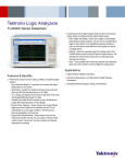
Tektronix Logic Analyzers
TLA6000 Series Data Sheet
Features & Benefits
Comprehensive Set of Signal Integrity Tools that Allow You to Quickly
Isolate, Identify, and Debug Complex Signal Integrity Issues
Glitch Trigger and Storage – Allows you to trigger on and highlight
potential signal integrity problems. Not only can the TLA6000 Series
trigger on the problem, but by highlighting suspected problems in
red, you will be able to easily determine which signals you need to
investigate further
iCapture – Route the suspected signal to the analog output of the
TLA6000 using the exclusive Tektronix iCapture feature. This
eliminates the need to double-probe with an oscilloscope probe,
reducing time to debug
iView – Time-correlated view of both logic analyzer and oscilloscope
data to trace the SI problem across the digital and analog domain
Performance and Ease of Use to Debug, Validate, and Optimize Digital
Systems
125 ps Resolution MagniVu™ Acquisition to Accurately See Signal
Relationships in Your System
State Speed – Sample your fastest synchronous buses with clock
rates up to 800 MHz and data rates up to 1.25 Gb/s
15 in. Display, with Optional Touch Screen to See More of Your Data
and Navigate Efficiently through Your Data
3 Models with 68/102/136 Channels and Up to 128 Mb Record Length
offer Flexible Solutions to Fit Any Budget
Drag-and-Drop Triggering – Simply drag any one of eight different
trigger types from a table onto the waveform and the TLA will
automatically set up the trigger conditions. Eliminates errors,
improves repeatability, and saves time
Drag-and-Drop Measurements – Simply drag an icon from the
measurement toolbar and drop it on your signal of interest and get
a table of results. Saves time, removes complexity, and reduces
measurement uncertainty
Analysis Tools for Debugging and Validating Today’s Digital Systems
FPGA
DDR
A Broad Selection of Microprocessor and Bus Support
MIPI CSI and DSI Debug
Applications
Digital Hardware Validation and Debug
Monitoring, Measurement, and Optimization of Digital Hardware
Performance
Embedded Software Integration, Debug, and Verification
Data Sheet
Efficiently Debug and Validate Your Digital
System at a Price You Will Like!
The affordable TLA6000 Series of logic analyzers offer the performance
needed to debug, validate, and optimize the functionality of your digital
system. The TLA6000 Series also provides a comprehensive set of signal
integrity debug tools that allow you quickly isolate, identify, and characterize
elusive and hard-to-find problems. Add a broad range of support for today’s
applications, and you have the ideal tool to help you meet all of the debug
challenges of today’s digital designs.
The TLA6000 Series allows you to effectively validate and debug the
functionality of your digital designs:
Use the patented 8 GHz MagniVu technology to accurately measure
timing relationships. The single, integrated acquisition architecture of the
TLA6000 Series eliminates the timing skew problems inherent in other
logic analyzer architectures
Capture on buses with clock rates up to 800 MHz and data rates up to
1.25 Gb/s
Buy the capability you need now and upgrade as your measurement
needs grow
Quickly isolate events through a simple and intuitive drag-and-drop
trigger setup
Easily summarize your design’s performance with sophisticated
drag-and-drop measurements such as frequency, period, pulse width,
duty cycle, and edge count
View data in a variety of time-correlated formats including waveform,
listing, graph, disassembly, source code, or compare
Find Tough Signal Integrity Problems
Today’s logic analyzers not only need to help troubleshoot functional issues
in your design, but also need to help find signal integrity problems caused
by crosstalk, termination mismatches, ground bounce, and other issues. To
help debug these problems, the TLA6000 Series includes a comprehensive
suite of signal debug tools.
These tools allow you to:
Use glitch trigger to monitor selected signals in your design and trigger
when a signal integrity problem is found on any one of these signals
Automatically tag any found signal integrity problems, allowing you to
quickly identify the signals of interest
Gain more insight into the problem using the exclusive iCapture
functionality to view both digital and analog data through a single probe
Use iView to see time-correlated digital and analog displays of your
data, letting you track the signal integrity problem across both analog
and digital domains
2
www.tektronix.com
TLA6000 Selection Guide
Characteristic
Channels
High-speed Timing
Maximum Timing
Sample Rate
(Quarter/Half/Full
channel)
Maximum State
Clock Rate
(Quarter/Half/Full
channel)
Maximum State
Data Rate
(Quarter/Half/Full
channel)
Maximum Record
Length
Analog Mux
Probing Options
TLA6202
TLA6203
TLA6204
68
102
136
8 GHz (125 ps) with 16 Kb record length
2 GHz / 1 GHz / 500 MHz
450 MHz / 450 MHz / 235 MHz (standard)
625 MHz / 800 MHz / 450 MHz (with Option 45)
900 Mb/s / 470 Mb/s / 235 Mb/s (standard)
1.25 Gb/s / 900 Mb/s / 450 Mb/s (with Option 45)
2 Mb (standard)
8 Mb with Option 1S
32 Mb with Option 2S
128 Mb with Option 3S
4 fixed channels (standard)
Any signal (user selectable) may be routed to
4 output BNCs with Option AM
P6810 General-purpose probe with Option 1P – supports
single-ended and differential signals
Mictor connections with Option 2P
P6960 D-Max probe with Option 3P
Characteristics
General
Characteristic
Description
Number of Channels (All channels are acquired including clocks)
TLA6202
68 channels (4 are clock channels)
TLA6203
102 channels (4 are clock and 2 are qualifier
channels)
TLA6204
136 channels (4 are clock and 4 are qualifier
channels)
Channel grouping
No limit to number of groups or number of
channels per group (all channels can be reused
in multiple groups)
Time Stamp
51 bits at 125 ps resolution (3.25 days duration)
Clocking/Acquisition
Modes
Asynchronous/Synchronous 8 GHz MagniVu
high-speed timing is available simultaneous with
all modes
Expansion Capability
The TLA6000 Series can be used as either a
master or expansion mainframe in systems
consisting of up to 8 TLA6000/TLA7000
instruments. A TL708EX Instrument Hub
and Expander is required when connecting
3-8 instruments together using TekLink™ cables
Tektronix Logic Analyzers — TLA6000 Series
PC Characteristics
Symbolic Support
Characteristic
Description
Characteristic
Description
Operating System
Microsoft® Windows® XP Professional and
Multilingual User Interface Pack
Number of
Symbols/Ranges
Unlimited (limited only by amount of virtual
memory available on TLA)
Processor
2.2 GHz Intel Core 2 Duo T7500
Chipset
Intel®
Object File Formats
Supported
Memory
1 GB DDR2 expandable to 2 GB DDR memory
Sound
Line In, Line Out, and Mic Out connectors
Removable Hard Drive
3.5 in., ≥80 GB Serial ATA, 7200 RPM
Optical Drive
Internal 4.7 GB DVD±R/RW
External Display Port
Type
One (1) DVI-I (primary – digital and analog)
connector and one (1) VGA connector
IEEE695, OMF 51, OMF 86, OMF 166,
OMF 286, OMF 386, COFF, Elf/Dwarf 1 and 2,
Elf/Stabs, TSF (If your software development
tools do not generate output in one of the
above formats, TSF, or the Tektronix symbol
file, a generic ASCII file format is supported.
The generic ASCII file format is documented
in the TLA User Manual). If a format is not
listed, please contact your local Tektronix
representative
External Display
Resolution
Up to 1600×1200 noninterlaced at 32-bit color,
each for both primary and secondary displays
965GME
Network Port
Two (2) 10/100/1000 LAN with RJ-45 connector
USB 2.0 Port
Seven (7); three (3) in front and four (4) in rear
Integral Controls
Characteristic
Description
Front-panel Display
Size: 15 in. (38.1 cm) diagonal
Type: Active-matrix color TFT LCD with backlight
Resolution: 1024×768
Simultaneous Display
Capability
Both the front-panel and one external display can
be used simultaneously at 1024×768 resolution
Front Panel
General-purpose knob with dedicated hotkeys
and knobs for horizontal and vertical scaling and
scrolling
Touch Screen
Available with Option 18
Integrated View (iView™) Capability
Characteristic
Description
TLA Mainframe
Configuration
Requirements
GPIB-iView (Opt. 1C) requires TLA Application
Software 5.0 or greater
Number of Tektronix
Oscilloscopes that can
be Connected to a TLA
System
1
External Oscilloscopes
Supported
More than 100. For a complete listing of currently
supported oscilloscopes, please visit our website
http://www.tektronix.com/iview
TLA Connections
USB, Trigger In, Trigger Out, Clock Out
Oscilloscope
Connections
External Instrumentation Interfaces
Characteristic
Description
System Trigger Output
Asserted whenever a system trigger occurs
(TTL-compatible output, back-terminated into
50 Ω)
System Trigger Input
Forces a system trigger (triggers all modules)
when asserted (adjustable threshold between
0.5 V and 1.5 V, edge sensitive, falling-edge
latched)
External Signal Output
Can be used to drive external circuitry from a
module’s trigger mechanism (TTL-compatible
output, back-terminated into 50 Ω)
External Signal Input
Can be used to provide an external signal to
arm or trigger any or all modules (adjustable
threshold between 0.5 V and 1.5 V, level
sensitive)
Power
Voltage Range/Frequency: 90-250 V AC at 45-66 Hz, 100-132 V AC at
360-440 Hz
Input Current: 7 A maximum at 90 V AC (70 A surge)
Power Consumption: 750 W maximum
Environmental
Characteristic
Description
Temperature
Operating: +5 °C to +45 °C
Nonoperating: –20 °C to +60 °C
Humidity
20% to 80%
Operating: ≤30 °C; 80% relative humidity (29 °C
maximum wet-bulb temperature)
Nonoperating: 8% to 80% (29 °C maximum
wet-bulb temperature)
GPIB, Trigger In, Trigger Out, Clock In (when
available) for the GPIB-iView cable (Opt. 1C)
Altitude
Operating: –1,000 ft. to 10,000 ft. (–305 meters
to 3,050 meters)
Setup
iView™ external oscilloscope wizard automates
setup
Safety
UL3111-1, CSA1010.1, EN61010-1, IEC61010-1
Data Correlation
After oscilloscope acquisition is complete, the
data is automatically transferred to the TLA and
time correlated with the TLA acquisition data
Physical Characteristics
Deskew
The oscilloscope and TLA data is automatically
deskewed and time correlated when using the
iView™ external oscilloscope cable
iView™ External
Oscilloscope Cable
Length
2m
Dimensions
mm
in.
Height
Width
Depth
295
451
460
11.6
17.75
18.1
Weight
kg
lb.
Net
Shipping (Typical)
17.1
30.1
36.7
66.7
www.tektronix.com
3
Data Sheet
Input Characteristics (with P6800 or P6900 Series probes)
Characteristic
Description
Capacitive Loading
0.5 pF clock/data (P6900 Series)
<0.7 pF clock/data (P6800 Series)
(1.0 pF for P6810 in group configuration)
Threshold Selection
Range
From –2.0 V to +4.5 V in 5 mV increments
Threshold presets include TTL (1.5 V), CMOS
(1.65 V), ECL (–1.3 V), PECL (3.7 V), LVPECL
(2.0 V), LVCMOS 1.5 V (0.75 V), LVCMOS 1.8 V
(0.9 V), LVCMOS 2.5 V (1.25 V), LVCMOS 3.3 V
(1.65 V), LVDS (0 V), and user defined
Threshold Selection
Channel Granularity
Separate selection for each of the clock/qualifier
channels and one per group of 16 data channels
for each 34-channel probe
Threshold Accuracy
(including probe)
±(35 mV + 1%)
Input Voltage Range
Operating
–2.5 V to 5.0 V
Nondestructive
±15 V
Timing Acquisition Characteristics
(with P6800 or P6900 Series probes)
Minimum Input Signal
Swing
300 mV (single ended)
V̄MAX – VMIN > 150 mV (differential)
Characteristic
Description
Input Signal Minimum
Slew Rate
200 mV/ns typical
MagniVu™ Timing
125 ps max, adjustments to 250 ps, 500 ps, 1 ns,
and 2 ns
MagniVu Timing
Record Length
16 Kb per channel, with adjustable trigger
position
Deep Timing
Resolution
(Quarter/Half/Full
channels)
500 ps / 1 ns / 2 ns to 50 ms
Deep Timing
Resolution with Glitch
Storage Enabled
4 ns to 50 ms
Deep Timing
Record Length
(Quarter/Half/Full
channels with time
stamps and with or
without transitional
storage)
8/4/2 Mb, 32/16/8 Mb, 128/64/32 Mb,
512/256/128 Mb per channel
Deep Timing Record
Length with Glitch
Storage Enabled
Half of default main memory depth
Channel-to-Channel
Skew
300 ps typical
Minimum Recognizable
Pulse/Glitch Width
(Single channel)
500 ps (P6960, P6964, P6980, P6982, P6860,
P6864, P6880), 750 ps (P6810)
Minimum Detectable
Setup/Hold Violation
250 ps
Minimum Recognizable
Multichannel Trigger
Event
Sample period + channel-to-channel skew
State Acquisition Characteristics
(with P6800 or P6900 Series probes)
Full Channel
235 MHz
450 MHz Optional
Half Channel
Quarter Channel
450 MHz / 450 Mb/s or
470 Mb/s (DDR)
800 MHz / 800 Mb/s or
900 Mb/s (DDR)
450 MHz / 900 Mb/s
625 MHz / 1.25 Gb/s
Note: When using SQUIRE adapters, the maximum clock rate / data rate is 300 MHz / 600 Mb/s.
Characteristic
Description
State Record Length
with Time Stamps
(Quarter/Half/Full channels) 8/4/2 Mb,
32/16/8 Mb, 128/64/32 Mb, 512/256/128 Mb per
channel
Setup-and-Hold Time
Selection Range
From 16 ns before, to 8 ns after clock edge
in 125 ps increments. Range may be shifted
towards the setup region by 0 ns [+8, –8] ns,
4 ns [+12, –4] ns, or 8 ns [+16, 0] ns
Setup-and-Hold Window
All channels
625 ps typical
Single channel
500 ps typical
Minimum Clock Pulse
Width
500 ps, 700 ps (P6810)
Active Clock Edge
Separation
400 ps
Demux Channel
Selection
Channels can be demultiplexed to other
channels through user interface with 8-channel
granularity
4
www.tektronix.com
Tektronix Logic Analyzers — TLA6000 Series
Analog Acquisition Characteristics
(with P6800 or P6900 Series probes)
Trigger Characteristics
Characteristic
Description
Characteristic
Description
16
Bandwidth
2 GHz typical
Independent Trigger
States
Attenuation
10X, ±1%
16
Offset and Gain
(Accuracy)
±50 mV, ±2% of signal amplitude
Maximum Independent
If/Then Clauses per
State
Channels
Demultiplexed
4
Maximum Number of
Events per If/Then
Clause
8
Run/Stop
Requirements
None, analog outputs are always active
8
iCapture™ Analog
Outputs
Compatible with any supported Tektronix
oscilloscope
Maximum Number of
Actions per If/Then
Clause
iCapture Analog Output
BNC Cable
Low loss, 10X, 36 in. Basic Analog Multiplexer
functionality is offered standard on all TLA6000
models. This routes 4 fixed channels to the
iCapture Analog Output BNCs. The outputs
cannot be switched to other logic analyzer
channels. Option AM enables full analog
multiplexer control and allows the routing of any
4 logic analyzer channels to the iCapture Analog
Output BNCs
Maximum Number of
Trigger Events
18 (2 counters/timers plus any 16 other
resources)
Number of Word
Recognizers
16
Number of Transition
Recognizers
16
Number of Range
Recognizers
4
Number of
Counters/Timers
2
Trigger Event Types
Word, Group, Channel, Transition, Range,
Anything, Counter Value, Timer Value, Signal,
Glitch, Setup-and-Hold Violation, Snapshot
Trigger Action Types
Trigger Module, Trigger All Modules, Trigger
Main, Trigger MagniVu, Store, Don’t Store, Store
Sample, Increment Counter, Decrement Counter,
Reset Counter, Start Timer, Stop Timer, Reset
Timer, Snapshot Current Sample, Goto State,
Set/Clear Signal, Do Nothing
Maximum Triggerable
Data Rate
1250 Mb/s (4X clocking mode)
Trigger Sequence Rate
DC to 500 MHz (2 ns)
Counter/Timer Range
51 bits each (>50 days at 2 ns)
Counter Rate
DC to 500 MHz (2 ns)
Timer Clock Rate
500 MHz (2 ns)
Counter/Timer Latency
2 ns
Range Recognizers
Double bounded (408 channel max). Can be as
wide as any group, must be grouped according
to specified order of significance
Setup-and-Hold
Violation Recognizer
Setup Time Range
From 8 ns before to 7 ns after clock edge in
125 ps increments. This range may be shifted
towards the positive region by 0 ns, 4 ns, or 8 ns
Setup-and-Hold
Violation Recognizer
Hold Time Range
From 7 ns before to 8 ns after clock edge in
125 ps increments. This range may be shifted
towards the positive region by 0 ns [+8, –8] ns,
4 ns [+12, –4] ns, or 8 ns [+16, 0] ns
Trigger Position
Any data sample
MagniVu Trigger
Position
MagniVu position can be set from 0% to 60%
centered around the MagniVu trigger
Storage Control
(Data qualification)
Global (conditional), by state (start/stop), block,
by trigger action, or transitional. Also force main
prefill selection available
www.tektronix.com
5
Data Sheet
Ordering Information
Recommended Accessories
TLA6202
Accessory
Description
LACART (2-shelf cart)
K4000 (3-shelf cart)
016-1522-xx
020-2664-xx
650-4815-xx
Logic Analyzer Cart
68-channel Logic Analyzer module, 8 GHz timing, 235 MHz state, 2 Mb record
length. Options for up to 128 Mb record length and/or up to 450 MHz state.
TLA6203
102-channel Logic Analyzer module, 8 GHz timing, 235 MHz state, 2 Mb record
length. Options for up to 128 Mb record length and/or up to 450 MHz state.
Wheeled Transport Case
Rackmount Kit
Additional Removable Hard Drive Assembly; No SW
TLA6204
136-channel Logic Analyzer module, 8 GHz timing, 235 MHz state, 2 Mb record
length. Options for up to 128 Mb record length and/or up to 450 MHz state.
All Include: Mini Keyboard (119-7275-xx), Optical Wheel Mouse (119-7054-xx),
Front-panel cover (200-4939-xx), TLA Application Software CD (063-3881-xx),
Certificate of Traceable Calibration.
Please specify probe, power, language, and service options when ordering.
Instrument Options
Option
Description
1P
Add full complement of P6810 (General-purpose)
probes
Add full complement of P6434 (Mictor) probes.
Includes SQUIRE adapters
Add full complement of P6960 (D-Max) probes
Increase to 8 Mb record length
Increase to 32 Mb record length
Increase to 128 Mb record length
Increase state speed to 450 MHz
Add full analog mux control
Add touch screen
Add iView cable
Add accessory pouch
Add TekLink cable
2P
3P
1S
2S
3S
45
AM
18
1C
PO
TL
6
www.tektronix.com
Power Plug Options
Description
Order Number
North America
Universal Euro
United Kingdom
Australia
240 V, North America
Switzerland
Japan
China
India
No power cord or AC adapter
161-0104-00
161-0104-06
161-0104-07
161-0104-14
161-0104-08
161-0167-00
161-A005-00
161-0306-00
161-0324-00
—
Option
A0
A1
A2
A3
A4
A5
A6
A10
A11
A99
Language Options
Option
Description
L0
English Manual
L5
Japanese Manual
L10
Russian Manual
L99
No Manual
Tektronix Logic Analyzers — TLA6000 Series
Upgrades
Service Options
Option
Description
CA1
Provides a single calibration event or coverage for
the designated calibration interval, whichever comes
first
Calibration Service, 3 Years
Calibration Service, 5 Years
Calibration Data Report
Calibration Data Report, 3 Years (with Option C3)
Calibration Data Report, 5 Years (with Option C5)
Repair Service, 3 Years
Repair Service, 5 Years
On-site Service, 1 Year
On-site Service, 3 Years (with R or C options)
Repair Service Coverage, 1-year Post Warranty
Repair Service Coverage, 2-year Post Warranty
Repair Service Coverage, 3 Years (includes product
warranty period). 3-year period starts at time of
instrument purchase
Repair Service Coverage, 5 Years (includes product
warranty period). 5-year period starts at time of
instrument purchase
C3
C5
D1
D3
D5
R3
R5
S1
S3
R1PW
R2PW
R3DW
R5DW
You can increase the state speed, memory depth, or add full analog multiplexer
capability to existing TLA6000 models by ordering the appropriate upgrade kit.
Please refer to the TLA Family Upgrade Guide for further details.
Product(s) are manufactured in ISO registered facilities.
Product(s) complies with IEEE Standard 488.1-1987, RS-232-C, and with Tektronix
Standard Codes and Formats.
www.tektronix.com
7
Data Sheet
Contact Tektronix:
ASEAN / Australasia (65) 6356 3900
Austria 00800 2255 4835*
Balkans, Israel, South Africa and other ISE Countries +41 52 675 3777
Belgium 00800 2255 4835*
Brazil +55 (11) 3759 7600
Canada 1 800 833 9200
Central East Europe, Ukraine, and the Baltics +41 52 675 3777
Central Europe & Greece +41 52 675 3777
Denmark +45 80 88 1401
Finland +41 52 675 3777
France 00800 2255 4835*
Germany 00800 2255 4835*
Hong Kong 400 820 5835
India 000 800 650 1835
Italy 00800 2255 4835*
Japan 81 (3) 6714 3010
Luxembourg +41 52 675 3777
Mexico, Central/South America & Caribbean (52) 56 04 50 90
Middle East, Asia, and North Africa +41 52 675 3777
The Netherlands 00800 2255 4835*
Norway 800 16098
People’s Republic of China 400 820 5835
Poland +41 52 675 3777
Portugal 80 08 12370
Republic of Korea 001 800 8255 2835
Russia & CIS +7 (495) 7484900
South Africa +41 52 675 3777
Spain 00800 2255 4835*
Sweden 00800 2255 4835*
Switzerland 00800 2255 4835*
Taiwan 886 (2) 2722 9622
United Kingdom & Ireland 00800 2255 4835*
USA 1 800 833 9200
* European toll-free number. If not accessible, call: +41 52 675 3777
Updated 25 May 2010
For Further Information. Tektronix maintains a comprehensive, constantly expanding
collection of application notes, technical briefs and other resources to help engineers working
on the cutting edge of technology. Please visit www.tektronix.com
Copyright © Tektronix, Inc. All rights reserved. Tektronix products are covered by U.S. and foreign patents,
issued and pending. Information in this publication supersedes that in all previously published material.
Specification and price change privileges reserved. TEKTRONIX and TEK are registered trademarks of
Tektronix, Inc. All other trade names referenced are the service marks, trademarks, or registered trademarks
of their respective companies.
07 Sep 2010
www.tektronix.com
52W-25734-0