1
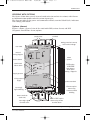
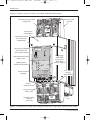
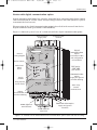
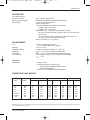
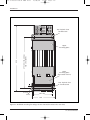
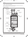
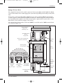
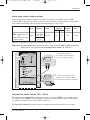
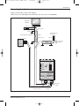
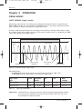
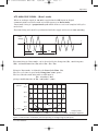
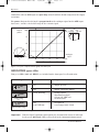
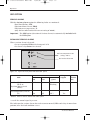
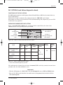
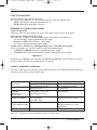
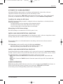
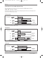
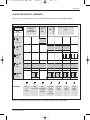
21/05/07
11:54
Page 1
ε
7100S
7100s.Cover ENG iss3.0
Single phase
solid state
contactors
ENG
• DATA MANAGEMENT • CONTROLS • PROCESS AUTOMATION•
User Manual
71S 0.Normes ENG ind 3
16/05/07
17:01
Page i
7100S
SMART CONTROLLERS
SINGLE-PHASE INDUSTRIAL SOLID STATE
CONTACTORS
7000 series
User
Manual
© Copyright Eurotherm Limited 2003
All rights reserved. All reproduction or transmission in any form whatsoever and using any procedure
(electronic or mechanical, including photocopying and recording) without written permission from
Eurotherm is strictly prohibited.
Ref.: HA176386ENG - Issue 3.0 - 05/2007
i
71S 0.Normes ENG ind 3
ii
16/05/07
17:01
Page ii
7100S User Manual
71S 0.Normes ENG ind 3
16/05/07
17:01
Page iii
Contents
CONTENTS
Page
European directives and applicable standards . . . . . . . . . . . .iv
Commissioning flowchart . . . . . . . . . . . . . . . . . . . . . . . . . . . . .vi
Chapter 1
Solid state contactor identification . . . . . . . . .1-1
Chapter 2
Installation . . . . . . . . . . . . . . . . . . . . . . . . . . . . . .2-1
Chapter 3
Operation (Firing, Alarms) . . . . . . . . . . . . . . . .3-1
Chapter 4
Commissioning and Maintenance . . . . . . . . . .4-1
Index . . . . . . . . . . . . . . . . . . . . . . . . . . . . . . . . . . . . . . . . . . . . . . . .5.1
Eurotherm business group addresses . . . . . . . . . . . . . . . . . .6-1
PURPOSE OF MANUAL
This manual (Issue 3.0) describes the Basic Version and all options for 7100S series
solid state contactors with current ratings of up to 250 A.
General information about the digital communication option is presented in the
technical specifications (section 1).
The operation of 7100S units with this option and the operation of the digital
communication are described in the ‘7000 Series. Digital Communication’ manual
(part number HA176664ENG).
7100S User Manual
iii
71S 0.Normes ENG ind 3
16/05/07
17:01
Page iv
Applicable standards
EUROPEAN DIRECTIVES AND APPLICABLE STANDARDS
COMPLIANCE WITH PRODUCT STANDARD
7100S products comply with the terms of product standard EN 60947-4-3
‘Contactors and motor-starters - AC semiconductor controllers and contactors for nonmotor loads’. The number of this standard is indicated on the front panel label.
CE LABELLING
7100S products, installed and used in accordance with their user manual, bear CE labelling
to indicate compliance with the essential requirements of:
• the European Low Voltage Directive 73/23 EEC dated 19 February 1973
amended by 93/68 EEC dated 22 July 1993
• the Electromagnetic Compatibility Directive 89/336/EEC dated 3 March 1969
amended by 92/31/EEC dated 28 April 1992 and 93/68/EEC dated 22 July 1993.
SAFETY
The units have IP20 protection rating as defined by standard IEC 60529.
External wiring must comply with standards IEC 60364-4-43 and IEC 60943.
Copper cables and conductors rated to a temperature of 75°C (167°F) must be used.
ELECTROMAGNETIC COMPATIBILITY (EMC) TEST STANDARDS
7100S products installed and used in accordance with the user manual, are designed for an
industrial environment and must not be used in the home.
IMMUNITY
The EMC immunity test standards required by product standard EN 60947-4-3 are given in
table 1.
Test type
Minimum levels
EMC test standard
Electrostatic discharge
4 kV on contact; 8 kV in air
EN 61000-4-2
Radiated, radio frequency
electromagnetic field
10 V/m 80 MHz ≤ f ≤ 1 GHz;
80% modulation 1 kHz sinusoidal
EN 61000-4-3
Electrical fast transient / burst
2 kV / 5 kHz
EN 61000-4-4
Electrical surge
4 kV line to earth;
2 kV line to line
EN 61000-4-5
Conducted disturbances
140 dBµV; 150 kHz ≤ f ≤ 80 MHz
EN 61000-4-6
Voltage dips, short interruptions
and voltage variation
5 s interruptions
EN 61000-4-11
Table 1 EMC immunity standards compliance
iv
7100S User Manual
71S 0.Normes ENG ind 3
16/05/07
17:01
Page v
Applicable standards
EMISSIONS
The EMC emissions test standards required by product standard EN 60947-4-3 are given in
table 2.
Emission type
Firing mode
EMC test standard
Radiated, radio frequency
All firing
modes
CISPR 11 Class A
Conducted, radio frequency
‘Burst mode’ and ‘Single-cycle’
CISPR 11 Class A
Group 2
‘Phase angle’
(Product compliant if external
series filter fitted)
Table 2 EMC emissions standards compliance
EMC GUIDE
To help you deal with installation-dependent electromagnetic interference effects,
Eurotherm provides an ‘Electromagnetic compatibility’ installation guide
(ref. HA025464) which sets out best current practice regarding EMC.
DECLARATION OF CONFORMITY
A CE declaration of conformity is available on request.
7100S User Manual
v
71S 0.Normes ENG ind 3
16/05/07
17:01
Page vi
Quick commissioning
COMMISSIONING FLOWCHART
Check characteristics of unit
and installation
Power wiring
Auxiliary supply
Input signal wiring
Power up
Check supply presence
vi
Product code
and specifications
correspond
Pages 1-7
to 1-13
Supply protection,
protective earth (PE terminal)
Pages 2-8, 2-9,
4-3
Power terminals
Supply: 1/L1, 3/L2 (1/L1 for ≥ 125A)
Load: 2/T1, 4/T2 (2/T1 for ≥ 125A)
Pages 2-7 to 2-9,
4-3
Fan:
FAN terminal block (rating = 250 A )
Pages 2-9, 4-3
24 Vdc or 24 Vac
(for MOP option) :
Aux2 terminal block
Page 2-12
DC logic signal:
LDC terminal block
AC logic signal:
HAC terminal block
4-20 mA analogue signal:
ATP terminal block
Digital signal (MOP option) :
COM terminal block
Page 2-10
Green ON LED
Apply input signal
Check firing
Green HEAT LED and
load current present
Pages 2-10, 3-4
Set DLF alarm: option
(if conditions met)
CHK/SET push button
Pages 3-9, 3-10,
4-3
Normal operation
ON and HEAT LEDs
Alarmes
signalées
Alarms signalled
GRF, DLF, T° LEDs
Pages 3-5 to 3-7
Maintenance
Pages 4-2, 4-3
7100S User Manual
71S 1.Identification ENG ind3
22/05/07
10:50
Page 1-1
Identification
Chapter 1
SOLID STATE CONTACTOR IDENTIFICATION
Contents
Page
General presentation . . . . . . . . . . . . . . . . . . . . . . . . . . . . . . . . . . . . . . . . .1-2
Basic version . . . . . . . . . . . . . . . . . . . . . . . . . . . . . . . . . . . . . . . . . . .1-2
Versions with options . . . . . . . . . . . . . . . . . . . . . . . . . . . . . . . . . . . .1-3
Technical specifications . . . . . . . . . . . . . . . . . . . . . . . . . . . . . . . . . . . . . . .1-7
Coding . . . . . . . . . . . . . . . . . . . . . . . . . . . . . . . . . . . . . . . . . . . . . . . . . . . . . .1-12
Example code . . . . . . . . . . . . . . . . . . . . . . . . . . . . . . . . . . . . . . . . . . .1-14
Identification label . . . . . . . . . . . . . . . . . . . . . . . . . . . . . . . . . . . . . .1-14
7100S User Manual
1-1
71S 1.Identification ENG ind3
22/05/07
10:50
Page 1-2
Identification
Chapter 1 IDENTIFICATION
GENERAL PRESENTATION
7100S series solid state contactors are used to control the electrical power of single phase
industrial loads. The load controlled may comprise low temperature coefficient resistive
loads or short wave infrared (SWIR) elements.
Current ratings vary from 16 A to 250 A (see coding), at voltages of 100 V to 500 V.
7100S series power thyristor units (rating of up to 100 A) comprise two channels, one
controlled by thyristors and one direct internal channel.
7100S units rated 125 A and above only comprise a single controlled channel.
BASIC VERSION (without options)
Power terminals
(supply side)
ε
User
label
EUROTHERM
7100 S
16A/230 V
1/L1
3/L2
2/T2
4/T2
PE
Internal wiring
diagram
Thyristor firing
request (logic)
Input logic signal
terminal labelling
Input logic signal
terminal block
Nominal current (rating)
and nominal voltage
ON
HEAT
EN 60947-4-3
LDC
Supply present
Protective earth
terminal
0VL LD
11 12
Product standard
Power terminals
(load side)
Figure 1-1 General view of 7100S, Basic version (here with DC logic input, 16 A rating)
1-2
7100S User Manual
71S 1.Identification ENG ind3
22/05/07
10:50
Page 1-3
Identification
VERSIONS WITH OPTIONS
The figures below show general views of 7100S units (100 and 250 A versions) with Alarms
or Communication options and with various input types.
The diagrams indicate the power and command terminals, terminal block labels, indicators
and settings push button.
Options (alarms)
Figure 1-2 shows a general view of the 7100S with GRF (serious alarms) and DLF
(Diagnostic Load Failure alarm) options.
Power terminals
(supply side)
User label
ε EURO THER M
Internal
wiring diagram
Serious alarms
3/L2
2/T1
4/T2
DLF option
CHK/SET
push button:
DLF alarm
setting / diagnosis
CHK
SET
EN 60947-4-3
ALR
HEAT
Firing request
(logic)
Input logic signal
terminal block
Alarm
options
ON
Supply present
Power terminals
(load side)
PE
GRF
DLF
1a 1b
73 74
Product standard
LDC
Input logic
signal labelling
7100 S
Rating (nominal current)
and nominal voltage
100 A / 500 V
1/L1
Partial load
failure alarm
Protective earth
terminal
0VL LD
11 12
Alarms option:
Alarm relay
contact terminal
labelling
GRF or DLF option:
Alarm relay contact
terminal block
Figure 1-2 General view of 7100S with DLF option (here with 100 A rating and DC logic input)
7100S User Manual
1-3
71S 1.Identification ENG ind3
22/05/07
10:50
Page 1-4
Identification
Figure 1-3 shows a general view of a fan-cooled 7100S unit with alarms.
Controlled phase terminal
(supply side)
Protective earth
terminal
1/L1
Not
used
Internal fuse
compartment
2 attachment screws
for internal fuse
compartment
Internal wiring diagram
(internal fuse for
125 to 250 A ratings)
710 0 S
ε EUR OTH ERM
Over-temperature alarm
(250 A only)
250 A / 500 V
PE
1/L1
DLF option:
CHK/SET
push button:
DLF alarm
setting / diagnosis
2/T1
Signalling LEDs
(alarms and operation)
GRF
CHK
SET
DLF
ON
Fuse blown
contact
(code MSFU)
ALR
230
N
L2
21 22
MSF
16 17 18
1a 1b
73 74
EXT
0VL LD
11 12
FAN
LDC
Control terminal
labelling
EN 60947-4-3
HEAT
3a 3b
75 76
Control
terminal block
Fan power supply
(250 A only)
Controlled phase
terminal
(load side)
2/T1
Not
used
Fan
Figure 1-3 General view of 7100S, 250 A rating (here with DLF, DC logic input, 230V fan power supply)
1-4
7100S User Manual
71S 1.Identification ENG ind3
22/05/07
10:50
Page 1-5
Identification
Version with digital communication option
Digital communication (RS485 bus) provides 7100S solid state contactors with digital control
and retransmission of various values and operating parameters (the DLF option is required
to transmit the load current).
The operation of the digital communication option is described in the manual ’7000 Series.
Digital Communication’ (part number HA176664ENG).
Figure 1-4 shows the general view of a 7100S unit with the digital communication option.
Protective earth
terminal
Power terminals
(supply side)
ε EURO THER M
1/L1
3/L2
2/T1
4/T2
Partial load
failure
alarm
ON/
Dxch
Rx
GRF
7
8
CHK
SET
6
DLF
Tx
3
2
ON
HEAT
Aux
B A
91 92
2
ALR
EN 60947-4-3
COM
Firing request
(burst mode)
1a 1b
73 74
GND 24V 0VS
15 19 20
Digital
Communication bus
terminal labelling
RS485 digital bus
terminal block
DLF option:
CHK/SET
push button
4
ON
Supply
present
Digital
communication
option:
Transmission LEDs
and configuration
microswitches
5
Serious alarms
PE
1
Internal
wiring diagram
7100 S
100 A / 500 V
Power terminals
(load side)
Communication
option:
Supply and ground
terminal labelling
Alarm relay
contact
terminal block
Communication option:
Supply and ground
terminals
Figure 1-4 General view of 7100S with DLF and communication options (here with 100 A rating)
7100S User Manual
1-5
71S 1.Identification ENG ind3
22/05/07
10:50
Page 1-6
Identification
1-6
7100S User Manual
71S 1.Identification ENG ind3
22/05/07
10:50
Page 1-7
Identification
TECHNICAL SPECIFICATIONS
USE
POWER
Nominal current
Nominal voltage
Frequency
Dissipated power
Cooling
LOAD
Categories of use
FIRING MODES
Thyristor switching
In accordance with product standard EN 60947-4-3:
Devices for continuous duty:
1. Semiconductor contactor variant 5:
Logic input signal:
• DC (LDC input) or
• AC (HAC input).
2. Thyristor unit variant 4:
4-20 mA analogue input signal (ATP input)
or digital communication option.
Configuration as product code.
16 A to 250 A (at 45°C) depending on product code
(see coding).
100 V to 500 V (+10% and -15%) available depending on
product code.
Use from 47 to 63 Hz (automatic matching)
typical 1.3 W per amp (2 W max., fuses included)
Natural convection (ratings up to 200 A) or
Fan (ratings over 250 A); consumption 10 VA
(115 V or 230 V external power supply).
The categories of use applicable for each unit are indicated
on the identification label.
• AC-51 Non-inductive or low inductance loads, furnace
resistances (resistive load with low temperature
coefficient).
• AC-55b Switching of incandescent lamps, short wave
infrared elements (SWIR).
At thyristor voltage zero crossing.
‘Logic’ mode
DC signal applied to LDC input
AC signal applied to HAC input
‘Burst’ mode
Supply voltage modulated by analogue signal applied to
ATP input
(Analogue to Time Proportional).
Firing base time: approx. 15 cycles
With ‘Digital Communication’ option
Firing base time:
• 1 half-cycle (‘Advanced single-cycle’ mode)
• 1 cycle (‘Single-cycle’ mode)
• 16 or 64 cycles (‘Burst mode’).
7100S User Manual
1-7
71S 1.Identification ENG ind3
22/05/07
10:50
Page 1-8
Identification
CONTROL
Power supply
‘Logic’ firing:
•DC signal
(LDC input)
• AC signal
(HAC input)
Self-powered electronics.
Conducting from 4.5 Vdc to 32 Vdc max, current ≥ 9 mA.
Off < 1.5 V or < 0.1 mA.
Typical response time ≤ 10 ms.
Conducting from 85 to 253 Vac max. Impedance ≈ 7 kΩ at 50 Hz.
Off < 10 Vac.
Typical response time ≤ 60 ms.
If an RC snubber contact protection circuit or control
optotriac is used, the maximum capacitor value is 22 nF
for 240 Vac
‘Burst mode’ firing:
• Analogue signal
(ATP input)
4 - 20 mA (10 Vdc max).
Modulation depending on analogue signal.
• Digital signals
(COM input)
Digital communication option
Modbus® protocol.
CONTROL
Control type
Linearity and Stability
ATP input only:
Open loop, no compensation of supply voltage variations.
Digital communication option:
Supply voltage compensation operates for variations of
up to ±20% of nominal voltage, using V2 control
Better than ±2% of full scale on sinusoidal supply.
SIGNALLING
All versions
Supply present
Thyristor firing request
Alarm option
Communication option
1-8
Green ‘ON’ LED.
Green ‘HEAT’ LED.
Red LED (serious alarms) GRF and / or
Orange LED (DLF alarm).
Alarm relay contact.
Front panel LEDs
Green LED (power supply and exchange status) and
two Orange LEDs (Receive and Transmit data).
Communication bus
Read and write operating parameters
(load current available with DLF option).
Retransmission of all types of alarm.
7100S User Manual
71S 1.Identification ENG ind3
22/05/07
10:50
Page 1-9
Identification
ALARMS (Options)
GRF option
Serious alarms
Signalling
DLF option
Diagnostic alarm
Signalling
Settings
Sensitivity
Extension
Over-temperature alarm
Operation
Signalling
Alarm relay
7100S User Manual
Total load failure (TLF) and thyristor short circuit (THSC)
detection.
When a serious alarm is detected:
• the red ‘GRF’ LED is lit
• the alarm relay contact is activated.
Partial load failure detection and diagnosis.
Important: For SWIR elements the DLF option applies:
• if the elements are powered at nominal voltage and
• in ‘Single-cycle’ mode only (available with digital
communication option or with Eurotherm REMIO/TPO
synchronised interface).
If a partial load failure (PLF fault) is detected:
• the orange ‘DLF’ LED is lit
• the alarm relay contact is activated.
The front panel push button is used for:
• monitoring and diagnosis
• adjusting and resetting the alarm.
Detects the failure of at least one heating element for six
identical elements connected in parallel
(one element in four for SWIR elements).
The DLF option includes Serious alarm monitoring
(GRF option included).
For all fan-cooled units (250 A), the unit stops firing if the
temperature threshold is exceeded regardless of the options
fitted.
Red ‘T°’ LED and Alarm relay contact
(if one of the alarm options is selected).
Fitted if one of the alarm options is selected.
The relay contact (0.25 A/230 Vac or 30 Vdc) is either open on
alarm or closed on alarm depending on the product code.
1-9
71S 1.Identification ENG ind3
22/05/07
10:50
Page 1-10
Identification
DIGITAL COMMUNICATION
Availability
The digital communication option is exclusive with:
• control using the logic or analogue input signal.
Protocol
Compliance
Modbus® RTU.
Communication complies with the specifications given in
‘GOULD MODICON Protocol Reference Guide PI-MBUS-300 rev J’.
Power supply
24 Vac (±20%), 47 to 63 Hz or
24 Vdc (±20%) non-polarised.
Typical consumption 1.5 VA
Protection: external 2 A fuse.
External wiring should comply with standard IEC 60364.
Transmission
Standard RS485, 2 wires.
Speed: 9600 or 19200 baud.
Selected by switch on front panel. The speed is factory set to
correspond to the selected product code.
Termination
The communication bus must have termination resistors fitted
at each end:
• one line impedance matching resistor.
• two RS485 bus polarisation resistors.
Address
Adjustable between 1 and 127 using front panel switches
only. The physical address is factory configured to 32 by default.
Diagnostic
•
•
Control
Parameters and
operating mode
Green LED on front panel indicates power presence, waiting
for frames, communication established.
Two orange LEDs show the status of the communication bus
(transmission or reception).
Supply voltage compensation operates for variations up to ±20%
of nominal voltage, using V2 control
Read and write by digital communication
(see Digital communication manual, part No. HA176664ENG).
Firing base time
Configurable over communication link:
• 1 half-cycle (‘Advanced single-cycle’ mode)
• 1 cycle (‘Single-cycle’ mode)
• 16 or 64 cycles (‘Burst mode’).
The default base time is factory configured to 16 cycles.
1-10
7100S User Manual
71S 1.Identification ENG ind3
22/05/07
10:50
Page 1-11
Identification
PROTECTION
Co-ordination type
for short circuits
Electrical protection
Thyristors
Type 1 (quick-acting fuses).
IP20 without adding additional protection.
Varistors and RC snubbers.
Quick-acting fuses
(except for Short wave infrared elements):
• rating ≤ 100 A: external
• rating ≥ 125 A: internal.
With MSFU code (selection corresponds to code):
• for external fuses, the fuse blown contact is wired directly
on the fuse;
• for internal fuses, the contact (open after fuse blows) is
accessible on the ‘MSF’ terminal block
Replacement fuses: see section 4.
ENVIRONMENT
Use
0 to 45°C at nominal current,
at maximum altitude of 1000 m.
-10°C to +70°C.
Assigned isolation voltage Vi = 500 Vrms
Degree 2 acceptable (defined by IEC 60664).
RH 5% to 95%, non-condensing, non-streaming.
Over-voltage category II (as defined by IEC 60664)
Vimp = 4 kV.
Storage
Isolation voltage
Pollution
Humidity
Over-voltage
Mounting
Mounting
DIMENSIONS AND WEIGHT
Rating
(A)
16
25
40
63
80-100
125-200
250
Height
(mm)
164
164
164
164
226
424
424
• rating ≤ 100 A:
attachment plate(s) fixed to unit:
- on symmetrical EN50022 DIN rail or
- bulkhead mounting.
• rating ≥ 125 A: bulkhead mounting only.
Width (mm)
Basic
Options
35
35
52.5
70
96
144
144
52.5
52.5
52.5
70
96
144
144
Depth (mm)
Basic
110
140
140
160
164
285
285
1 Option 2 Options
135
165
165
185
189
285
285
160
190
190
210
214
372
372
Mass (kg)
Basic
Options
0.42
0.56
0.8
1.3
1.7
5.1
5.6
0.56
0.7
0.9
1.45
1.85
5.6
6.0
Eurotherm’s policy of continuous product improvement and development means that the specifications in this document may
be modified without prior notice.
7100S User Manual
1-11
71S 1.Identification ENG ind3
22/05/07
10:50
Page 1-12
Identification
CODING
7100S Current / Voltage / Filter / Fan / Fuse / Input / Manual / Selected /
options
Ratings and Basic selection
1. Nominal current
Code
6. Input
Code
16 amps
25 amps
40 amps
63 amps
80 amps
100 amps
125 amps
160 amps
200 amps
250 amps
16A
25A
40A
63A
80A
100A
125A
160A
200A
250A
Modbus digital communication
option (without logic or
analogue input)
NONE
2. Nominal voltage
Code
No communication.
Logic firing:
DC logic signal
4.5 Vdc to 32 Vdc
AC logic signal
85 Vac to 253 Vac
‘Burst mode’ firing:
Analogue DC signal
4 mA to 20 mA
127 volts
230 volts
277 volts
500 volts
127V
230V
277V
500V
7. Manual language
French
English
German
3. XXXX
4. Fan
Code
16A to 200A:
no fan
XXXX
250A: fan
• 115 V supply
• 230 V supply
115V
230V
5. High speed fuse
Code
8. Selected options
LDC
HAC
ATP
Code
FRA
ENG
GER
Code
No options
End of code
NONE
Selection of options
YES
Thyristor protection fuse
• without microswitch
• with microswitch
(100 A: external fuse
≥ 125 A: internal fuse)
No fuse or control of
short wave infrared elements
1-12
FUSE
MSFU
NONE
7100S User Manual
71S 1.Identification ENG ind3
22/05/07
10:50
Page 1-13
Identification
Alarm option
Type / Load / Contact /
Communication Option
Protocol / Transmission Speed
Certificate
option
Options (Options selected: YES)
9. Alarm option
Code
Serious Alarms:
Thyristor short-circuit,
Total Load failure,
(over-temperature for ≥ 250 A) GRF
Partial load failure
DLF
and Serious alarms
No alarms
NONE
10. Load type
Code
For DLF option:
• Resistive load with
LTCL
low temperature coefficient
• Short wave infrared elements SWIR
Without DLF option
11. Alarm relay contact
Code
Digital communication
Modbus® protocol
MOP
No communication
NONE
13. Transmission speed
Code
Code MOP.
Transmission speed:
9.6 kbaud
19.2 kbaud
9K6
19K2
Code NONE.
No communication
XXXX
14. Certification option
Code
Without certificate of
‘Compliance with Order’
NONE
With certificate of
‘Compliance with Order’
CFMC
XXXX
Code
GRF or DLF option:
Alarm relay contact
• Closed on alarm
• Open on alarm
NC
NO
Without alarm option
XX
7100S User Manual
12. Communication option
1-13
71S 1.Identification ENG ind3
22/05/07
10:50
Page 1-14
Identification
EXAMPLE CODE
Nominal load current
Supply voltage
Thyristor protection fuse
Firing and input
Manual language
Option
Load used
Alarm relay contact
Digital communication
Certification
100 amps.
230 volts (EMC filter required).
Yes, with microswitch.
‘Burst mode’ with analogue signal.
English.
Serious alarms and ‘Partial load failure’ alarm.
Resistance with low temperature coefficient.
Open on alarm.
No digital communication.
Certificate of ‘Compliance with order’
Corresponding product code:
7100S 100A/230V/FILT/XXXX/MSFU/ATP/ENG/YES/DLF/LTCL/NO/NONE/XXXX/CFMC
IDENTIFICATION LABEL
An identification label, giving full information about the characteristics of the unit and the
product identification code, is affixed to the left hand side of the unit.
Location of
head office
Product
code
Manufacturing code
EUROTHERM Worthing, England
Tel.: +44 1903 268500
7100S code: 100A/230V/FILT/XXXX/MSFU/ATP/ENG/YES/DLF/LTCL/NO/
NONE/XXXX/CFMC
Serial number
Date of manufacture Serial number: FC35048 - 2 - 30 - 08 - 03
Rating
Nominal voltage
Input type
Customer
order number
100 A 230 V @45°C Input 4 -20 mA
PO No.: 11826
Safety instructions: see user manual
Load Type (EN 60947-4-3): AC51
External Fuse
Fuse code: CS173246U160
Position of fuse
(external or internal)
Eurotherm fuse reference
depending on code
(except for SWIR elements)
Made in France
Category of use
in accordance with
product standard EN 60947-4-3
Figure 1-5 Typical identification label (corresponds to example code)
1-14
7100S User Manual
71S 2.Installation ENG ind 3
21/05/07
11:40
Page 2-1
Installation
Chapter 2
INSTALLATION
Contents
Page
Safety during installation . . . . . . . . . . . . . . . . . . . . . . . . . . . . . . . . . . . . . .2-2
Mounting . . . . . . . . . . . . . . . . . . . . . . . . . . . . . . . . . . . . . . . . . . . . . . . . . . . .2-3
Types of mounting . . . . . . . . . . . . . . . . . . . . . . . . . . . . . . . . . . . . . . . .2-3
Attachment plate . . . . . . . . . . . . . . . . . . . . . . . . . . . . . . . . . . . . . . . . . .2-3
Mounting on DIN rails . . . . . . . . . . . . . . . . . . . . . . . . . . . . . . . . . . . . .2-4
Bulkhead mounting . . . . . . . . . . . . . . . . . . . . . . . . . . . . . . . . . . . . . . .2-5
Wiring . . . . . . . . . . . . . . . . . . . . . . . . . . . . . . . . . . . . . . . . . . . . . . . . . . . . . . .2-7
Power connections . . . . . . . . . . . . . . . . . . . . . . . . . . . . . . . . . . . . . . . .2-7
Wiring diagrams . . . . . . . . . . . . . . . . . . . . . . . . . . . . . . . . . . . . . .2-8
16 A to 100 A . . . . . . . . . . . . . . . . . . . . . . . . . . . . . . . . . . . . . . .2-8
125 A to 250 A . . . . . . . . . . . . . . . . . . . . . . . . . . . . . . . . . . . . . .2-9
Control connections . . . . . . . . . . . . . . . . . . . . . . . . . . . . . . . . . . . . . . .2-10
Control signal . . . . . . . . . . . . . . . . . . . . . . . . . . . . . . . . . . . . . . . .2-10
Alarm relay contact (Alarm option) . . . . . . . . . . . . . . . . . . . .2-11
Internal fuse blown contact (125-250 A) . . . . . . . . . . . . . . . . . .2-11
Reference voltage (125-250 A) . . . . . . . . . . . . . . . . . . . . . . . . . . .2-12
Connecting the digital communication . . . . . . . . . . . . . . . . . .2-13
7100S User Manual
2-1
71S 2.Installation ENG ind 3
21/05/07
11:40
Page 2-2
Installation
Chapter 2
installation
SAFETY DURING INSTALLATION (MOUNTING AND WIRING)
Danger!
• 7100S solid state contactors must be installed and wired by qualified staff
authorised to work on low voltage industrial electrical facilities.
• Units must be installed in a fan-cooled cabinet, to ensure that condensation and
pollution are excluded. We recommend fitting fan-cooled cabinets with a fan
failure detection device or a thermal safety cut-out.
The cabinet must be closed and connected to the protective earth according to
IEC 364 or applicable national standards.
• Units must be mounted with the heatsink positioned vertically, and with no
obstructions above or below the unit which could reduce or hamper air flow.
If several units are fitted in the same cabinet, arrange them such that air from
one unit is not drawn in by the unit above.
Leave a gap of at least 10 mm between two adjacent units.
Important!
!
• Nominal currents correspond to use at ambient temperatures of no more than
45°C. Overheating may cause incorrect operation and may even lead to
components being damaged.
Danger!
• It is the user’s responsibility to wire and protect the facility according to best
practice and applicable standards.
A suitable device, ensuring that the unit can be electrically isolated from the
supply, must be installed upline to enable work to be performed safely.
Conductor cross-sections should comply with IEC 943.
Use only copper cables and wires designed for use at up to 75°C.
• Before connecting or disconnecting the unit check that power and control cables
and leads are isolated from voltage sources.
The protective earth must be connected before any other connections are made
and should be the last cable to be disconnected.
The protective earth connection terminal is marked with the symbol
Important!
!
2-2
• To ensure that 7100S solid state contactors comply with Electromagnetic
Compatibility requirements, ensure that the panel or DIN rails to which they are
attached is correctly grounded.
The ground connection, designed to ensure ground continuity, is not in any way
a substitute for the protective earth connection.
7100S User Manual
71S 2.Installation ENG ind 3
21/05/07
11:40
Page 2-3
Installation
MOUNTING
TYPES OF MOUNTING
Two types of mounting are possible:
• DIN rail mounting or
• bulkhead mounting with screws.
Current
rating
DIN rail mounting
Bulkhead mounting
Attachment
plate
DIN rails
Attachment
plate
Screws
One vertical
plate
One EN 50022
symmetric rail
One vertical
plate
2 × M4
80 A and 100 A Two horizontal Two EN50022
plates
symmetric rails
Two horizontal
plates
4 × M4
≥ 125 A
Two plates with
keyhole-type holes
4 × M6
16 A to 63 A
Not suitable
Table 2-1 Attachment details for both mounting types
Ratings 16 A to 100 A
Each attachment plate has:
• two fixed hooks and two mobile hooks for clipping to a DIN rail; the mobile hooks are
moved using a catch and spring (figures 2-1 and 2-2)
• attachment holes for bulkhead mounting (figures 2-3 and 2-4).
For DIN rail mounting (figures 2-1 and 2-2):
• fix one symmetric DIN rail (rating 16 A to 63 A) or two rails (rating 80 A and 100 A), in
accordance with the unit dimensions and safety recommendations
• place the unit against the top rail, engaging the two fixed hooks
• push the unit against the rails
• clip the unit onto the bottom rail using the mobile hooks, ensuring that they are
properly engaged.
To remove the unit:
• move the mobile hooks downwards by pulling on the catch
• unclip the unit from the rail.
Ratings 125 A to 250 A
For bulkhead mounting, two attachment plates are provided, each with two keyhole-type
mounting holes to allow clearance for the heads of the M10 screws (figure 2-5).
7100S User Manual
2-3
71S 2.Installation ENG ind 3
21/05/07
11:40
Page 2-4
Installation
MOUNTING ON DIN RAILS
Attachment plate
Attachment hooks
82
164
DIN EN50022 rail
Mobile attachment hooks
Catch to move mobile
hooks downwards
Figure 2-1 Attaching the 7100S solid state contactor to a DIN rail (16 A to 63 A, rear view)
Upper attachment plate
125
226
Attachment hooks
DIN EN50022
rails
Mobile attachment hooks
Catch to move mobile
hooks downwards
Lower attachment plate
Figure 2-2 Attaching the 7100S solid state contactor to DIN rails (80 A and 100 A, rear view).
2-4
7100S User Manual
71S 2.Installation ENG ind 3
21/05/07
11:40
Page 2-5
Installation
BULKHEAD MOUNTING
For M4 screw
164
156 ± 0.5
Attachment plate
For M4 screw
Figure 2-3 Mounting the unit using an attachment plate for bulkhead mounting (16 A to 63 A, rear view)
For two M4 screws
226
210 ± 0.5
Upper
attachment plate
Lower
attachment plate
For two M4 screws
80 ± 0,5
Figure 2-4 Mounting the unit using an attachment plate for bulkhead mounting (80 A and 100 A, rear view).
7100S User Manual
2-5
71S 2.Installation ENG ind 3
21/05/07
11:40
Page 2-6
Installation
Two 'keyhole' slots
for M6 screws
275 ± 0.5 (125 - 200 A)
325 ± 0.5 (250 A)
424
Upper
mounting plate
Lower
mounting plate
(fan-cooled version)
Two 'keyhole' slots
for M6 screws
11
∅ 12
∅ 6.5
124 ± 0.5
144
Figure 2-5 Bulkhead mounting for ratings 125 A to 250 A (fan-cooled unit, rear view).
2-6
7100S User Manual
71S 2.Installation ENG ind 3
21/05/07
11:40
Page 2-7
Installation
WIRING
POWER CONNECTIONS
The protective earth terminal PE (marked with the earth symbol) must be wired to the
protective earth (see section ‘Safety during installation’).
Ratings 16 A to 100 A
7100S units with current ratings of up to 100 A have:
• one channel controlled by thyristors
• an internal busbar for directly connecting the load to the power supply
(direct channel, not controlled by thyristors).
The wiring diagram for this range of standard current ratings is shown in figure 2-6:
• terminals 1/L1 (controlled channel) and 3/L2 (direct channel) on the unit must be
wired to the supply network
• terminals 2/T1 (controlled channel) and 4/T2 (direct channel) on the unit must be
wired to the load.
Ratings 125 A to 250 A
7100S units with current ratings from 125 A to 250 A have one channel controlled by
thryistors (terminals 1/L1 and 2/T1). The direct phase is wired externally (between the
load and the second phase or neutral, as on figure 2-7).
The second phase (or neutral) used must be connected to the ‘EXT’ terminal block
to provide the reference voltage for control (see figure 2-7).
Wiring details
Rating
A
16
40
80
to
to
to
125
160
200
250
Terminal capacity *
AWG
mm2
25
63
100
2.5 to
6 to
16 to
6
16
35
50 to
70 to
95 to
120
120
120
120
14 to
10 to
6 to
Stripping
length
mm
10
6
2
1/0 to 4/0
2/0 to 4/0
3/0 to 4/0
4/0
Crimp
eyelet
13
13
20
-
Clamping
torque
Nm
∅10 (or ∅12)
1.2
1.8
3.8
16.4 (or 28.8)
M10 nut (17 mm
wrench) to attach
eyelet and terminal.
Table 2-2 Power connection details for ratings from 16 A to 250 A
* For certain flexible cables (up to 35 mm2) a screw connector should be used.
7100S User Manual
2-7
71S 2.Installation ENG ind 3
21/05/07
11:40
Page 2-8
Installation
POWER CONNECTION DIAGRAM
The power connection to 7100S units is between one phase and neutral or between two
phases depending on the nominal voltage for the unit.
Ratings 16 A to 100 A
Supply protection
and cut-out
installed by user
L1
L2 (N)
External
thyristor protection
fuse
Direct channel
terminal
(supply side)
Protective earth
connection
Controlled channel
terminal
(supply side)
ε
Internal power
wiring diagram
EUROTHERM
1/L1
3/L2
2/T1
4/T2
Input signal
terminal
labelling
(depends on input type)
Protective earth
terminal
PE
ON
HEAT
EN 60947-4-3
LDC
Input signal
terminal block
7100S
100 A / 500 V
0VL LD
11 12
Input signal
connection
Controlled channel
terminal
(load side)
Load
Direct channel
terminal
(load side)
Figure 2-6 Power connections and input signal on Basic version (ratings up to 100 A)
2-8
7100S User Manual
71S 2.Installation ENG ind 3
21/05/07
11:40
Page 2-9
Installation
Ratings 125 A to 250 A
The controlled channel of the 7100S is connected between a phase and the load; the direct,
exrenal link connects the second supply phase (or neutral, depending on the voltage used) to the
load.
For the 250 A rating the fan power supply must be connected to the FAN terminal block.
A 115 V supply is connected to terminals 17 and 18 or a 230 V supply to terminals 16 and
18, depending on the product code. This external power supply must be protected by a 2 A
fuse (2 fuses if the auxiliary supply is line to line).
The internal fuse blown contact (with code MSFU) is available on the MSF terminal block
(see details on figure 2-9).
L1
Supply protection
and cut-out
installed by user
Controlled channel
terminal
(supply side)
L2 (N)
1/L1
Internal fuse compartment
(thyristor protection)
Internal power
wiring diagram
Protective
earth
terminal
ε EUROTHERM
7100 S
250 A / 500 V
1/L1
Direct
channel
PE
230
N
16 17 18
EXT
0VL LD
11 12
FAN
LDC
2/T1
L2
21 22
ON
Input signal
terminal
block
(e.g. DC Logic)
Fan power
supply terminal
block
(e.g. 230 V)
2A
230
N
16 17 18
L2
MSF
0VL LD
11 12
EN 60947-4-3
EXT
2A
FAN
+
LDC
HEAT
Second phase
(or neutral)
for reference
Controlled channel
terminal
(load side)
Internal
fuse blown
contact
(MSFU)
3a 3b
75 76
21 22
2A
2/T1
Reference
voltage
Load
Figure 2-7 Power and control connections for 7100S (here 250 A rating, Basic version)
7100S User Manual
2-9
71S 2.Installation ENG ind 3
21/05/07
11:40
Page 2-10
Installation
CONTROL CONNECTIONS
The control terminal blocks are plug-in screw connectors, located
on the underside the unit (see figures 1-1 to 1-5).
Control signal
The control signal input terminals correspond to the selected input type.
Input code and type
Terminal
block
Terminal Terminal
number label
Terminal
Clamping Stripping
capacity
torque
mm
mm2 AWG
Nm
LDC: Logic,
4.5 - 32 Vdc
LDC
11
12
0V
LD
1.5
16
0.5
6 to 7
HAC: Logic,
85 - 253 Vac
HAC
11
12
A1
A2
2.5
14
0.7
6 to 7
ATP: Analogue,
4 - 20 mA DC
ATP
11
12
0V
RI
1.5
16
0.5
6 to 7
Table 2-3 Description of control input terminal block
Input signal
terminal block
11 12
+
DC logic
7100 S
A1 A2
ATP
0V LD
HAC
LDC
ε EUROTHE RM
11 12
or
or
AC logic
Figure 2-8 Front panel labels for the different input types
0V RI
11 12
+
DC analogue
Important!
!
2-10
The DC inputs (LDC and ATP) are polarised.
The ‘+’ of the control signal must be connected to terminal 12
(labelled LD for the LDC input and RI for the ATP input).
7100S User Manual
71S 2.Installation ENG ind 3
21/05/07
11:40
Page 2-11
Installation
Alarm relay contact (alarm option)
If one of the alarm options is fitted, an alarm relay contact is available on the ‘ALR’
terminal block. The type of contact (closed or open on alarm) is determined by the product
code. Contact switching capacity: 0.25 A (maximum 250 Vac or 30 Vdc).
Option Code
Terminal Terminal
block
number
GRF: serious alarms
or
DLF: DLF alarm and
serious alarms
ALR
Terminal
label
Code NC:
71 , 72
Code NO:
73, 74
1a, 1b
Terminal
Clamping
capacity
torque
Nm
mm2 AWG
2.5
14
Stripping
mm
0.7
6 to 7
Table 2-4 Description of Alarm relay contact terminal block
Important: For fan-cooled units (250 A and above) with either the GRF or DLF options the
ALR contact also signals the over-temperature alarm (‘T°’ LED on).
ε EUROTHERM
1/L1
PE
ALR
Internal
fuse
7100 S
250 A / 500 V
1a
1b
Alarm relay contact
71, 72: contact closed on alarm
73, 74: contact open on alarm
73 74
2/T1
GRF
CHK
SET
DLF
EN 60947-4-3
N
1a 1b
3a 3b
75 76
73 74
L2
21 22
MSF
230
16 17 18
EXT
0VL LD
FAN
LDC
ALR
HEAT
11 12
MSF
ON
Internal fuse blown contact
(rating ≥ 125 A and code MSFU)
75, 76: contact closed when fuse blown
3a 3b
77 78
Figure 2-9 Alarm and fuse blown contact connections (here with internal fuse, fan-cooled unit, logic signal)
Internal fuse blown contact (125 - 250 A)
For units with an internal fuse (ratings 125 to 250 A) and code MSFU, a fuse blown contact
is available on the ‘MSF’ terminal block (see figure 2-9). The terminal capacity and torque
are identical to those for the alarm contact (table 2-4).
The normally-closed fuse blown contact is connected when the unit leaves the factory.
7100S User Manual
2-11
71S 2.Installation ENG ind 3
21/05/07
11:40
Page 2-12
Installation
Reference voltage connections (125 - 250 A)
For ratings between 125 and 250 A the non-controlled phase is connected outside the unit.
To make the reference voltage available for the electronic circuits, the power voltage must be
wired to the unit.
This external wiring uses terminal L2 on the ‘EXT’ terminal block (125 to 250 A only).
Terminal L2 must be connected to the second phase (or neutral) of the power supply. This
link must be protected by a 2 A fuse (see figure 2-7, page 2-9).
The second terminal of this terminal block is not used.
Rating
A
16 - 100
125 - 250
Terminal Terminal
block
number
EXT
21, 22
Terminal
label
L2 , -
Table 2-5 Description of reference voltage terminal block
2-12
Terminal
Clamping
capacity
torque
Nm
mm2 AWG
Stripping
mm
-
-
-
-
2.5
14
0.7
6 to 7
7100S User Manual
71S 2.Installation ENG ind 3
21/05/07
11:40
Page 2-13
Connecting the digital communication
Installation
Digital communication option basic diagram.
Please refer to the 7000 Digital Communication user manual ref : HA176664ENG.
Supervisor
(Master)
220 Ω
Bus line A
Masse
Communication bus RS485
24 Vac
or
24 Vdc
Fuse
2A
On the last unit
of the bus
Shield
Bus line B
220 Ω
To the next
interface
Auxiliary
supply
ON/
Dxch
Rx
Tx
8
GRF
5
6
7
CHK
SET
4
DLF
HEAT
1
ON
2
3
ON
EN 60947-4-3
Digital communication
block terminal
Figure 2-10 Digital communication connection
Manuel Utilisateur 7100S
24V 0VS GND
19 20 29
x2
A B
91 92
Au
CO
M
ALR
1a 1b
73 74
Auxiliary
supply
Protective
earth
2-13
71S 2.Installation ENG ind 3
21/05/07
11:40
Page 2-14
Installation
2-14
Manuel Utilisateur 7100S
71S 3.Fonctionnement ENG ind3
16/05/07
16:51
Page 3-1
Operation
Chapter 3
OPERATION
Contents
Page
Firing modes . . . . . . . . . . . . . . . . . . . . . . . . . . . . . . . . . . . . . . . . . . . . . . . . .3-2
Logic signals (‘Logic’ mode) . . . . . . . . . . . . . . . . . . . . . . . . . . . . . . . .3-2
ATP analogue signal (‘Burst’ mode) . . . . . . . . . . . . . . . . . . . . . . . . .3-3
Indicators (green LEDs) . . . . . . . . . . . . . . . . . . . . . . . . . . . . . . . . . . . . . . .3-4
Alarms (Options) . . . . . . . . . . . . . . . . . . . . . . . . . . . . . . . . . . . . . . . . . . . . .3-5
Safety mechanisms . . . . . . . . . . . . . . . . . . . . . . . . . . . . . . . . . . . . . . . .3-5
Alarm strategy . . . . . . . . . . . . . . . . . . . . . . . . . . . . . . . . . . . . . . . . . . . .3-5
Alarms detected . . . . . . . . . . . . . . . . . . . . . . . . . . . . . . . . . . . . . . .3-5
Firing inhibit . . . . . . . . . . . . . . . . . . . . . . . . . . . . . . . . . . . . . . . . .3-5
Signal alarms . . . . . . . . . . . . . . . . . . . . . . . . . . . . . . . . . . . . . . . . .3-5
Memorisation / Reset . . . . . . . . . . . . . . . . . . . . . . . . . . . . . . . . . .3-5
Alarm relay . . . . . . . . . . . . . . . . . . . . . . . . . . . . . . . . . . . . . . . . . .3-5
GRF option . . . . . . . . . . . . . . . . . . . . . . . . . . . . . . . . . . . . . . . . . . . . . . .3-6
Serious alarms . . . . . . . . . . . . . . . . . . . . . . . . . . . . . . . . . . . . . . . .3-6
Signalling serious alarms . . . . . . . . . . . . . . . . . . . . . . . . . . . . . .3-6
DLF option (Load failure diagnostic alarm) . . . . . . . . . . . . . . . . . .3-7
Functions of the DLF option . . . . . . . . . . . . . . . . . . . . . . . . . . .3-7
Signalling alarms with DLF option . . . . . . . . . . . . . . . . . . . . . .3-7
Load type matching . . . . . . . . . . . . . . . . . . . . . . . . . . . . . . . . . . .3-8
Reminder of possible firing modes . . . . . . . . . . . . . . . . . . . . .3-8
Correct operating conditions . . . . . . . . . . . . . . . . . . . . . . . . . . .3-8
Automatic DLF alarm adjustment . . . . . . . . . . . . . . . . . . . . . . .3-9
Partial load failure detection conditions . . . . . . . . . . . . . . . . .3-9
Partial load failuredetection sensitivity . . . . . . . . . . . . . . . . . .3-9
Alarm confirmation . . . . . . . . . . . . . . . . . . . . . . . . . . . . . . . . . .3-9
Functions of DLF alarm push button . . . . . . . . . . . . . . . . . . . .3-10
Alarm diagnostic summary . . . . . . . . . . . . . . . . . . . . . . . . . . . . . . . .3-11
7100S User Manual
3-1
71S 3.Fonctionnement ENG ind3
16/05/07
16:51
Page 3-2
Operation
Chapter 3
OPERATION
FIRING MODES
LOGIC SIGNALS (‘Logic’ mode)
When logic signals (DC or AC voltages depending on the product code) are applied to the
LDC or HAC inputs, the 7100S unit fires in ‘Logic’ mode (i.e. operation equivalent to solid
state contactors). Firing corresponds to supply half-cycles.
In ‘Logic’ mode thyristor firing starts and stops at zero voltage crossing, taking into account
the response time (delay relative to signal). The typical response time is ≤ 10 ms for the LDC
input and ≤ 60 ms for the HAC input.
Logic signal
Supply
voltage
Load voltage
t
Zero-crossing
switching
Response time
Figure 3-1 Thyristor firing in ‘Logic’ mode
Zero-crossing
cut off
Response time
Thyristor firing:
• is enabled when the input signal is greater than or equal to the ‘On’ value.
• is disabled when the input signal is less than the ‘Off’ value.
Logic input
type
Code
Low level DC
LDC
0VL, LD
High level AC
HAC
A1, A2
Table 3-1
Logic input parameters
Terminal
labels
On
Off
Max.
voltage
4.5 Vdc
1.5 Vdc
32 Vdc
85 Vac
10 Vac
253 Vac
Important: 7100S solid state contactors with the digital communication option gradually
vary the power transmitted to the load in ‘Burst mode’ (IHC, FC1, C16, C64)
depending on the digital setpoint.
3-2
7100S User Manual
71S 3.Fonctionnement ENG ind3
16/05/07
16:51
Page 3-3
Operation
ATP ANALOGUE SIGNAL (‘Burst’ mode)
When an analogue signal (4 - 20 mA) is applied to the ATP input (or Digital
communication is used) the 7100S series unit operates in ‘Burst mode’.
‘Burst mode’ firing is a proportional cycle which delivers a series of complete half-cycles
to the load.
Thyristor firing and cut-off is synchronised with the supply and occurs at zero crossing.
Load
voltage
t
TF
TM
TNF
Figure 3-2 Thyristor firing in ‘Burst mode’
Thyristor firing in ‘Burst mode’ can be described by the firing time (TF) , non-firing time
(TNF) and modulation time (TM) where TM = TF + TNF
Firing in ‘Burst mode’ is defined by the Base Cycle Time (TB).
The base cycle time is equal to the firing time at 50% power.
The base time for 7100S units with an ATP input is:
TB = 15 cycles ± 20%
giving a modulation time of TM = 30 cycles s ± 20%.
Modulation TM
period
5.0 s
4.0 s
3.0 s
2.0 s
TB = 0.3 s
(TF = TNF)
1.0 s
0.6 s
0
25%
50%
75%
100%
Output power
(analogue setpoint)
Figure 3-3 ‘Burst mode’ modulation period depending on analogue signal (ATP input)
7100S User Manual
3-3
71S 3.Fonctionnement ENG ind3
16/05/07
16:51
Page 3-4
Operation
7100S units with an ATP input use open loop control and thus do not compensate for supply
variations.
The power dissipated in the load is proportional to the analogue signal on the ATP input
between 4% and 96% of the full range of the 4-20 mA signal.
100%
Output
power
19.4 mA
20 mA
75
50
25
4 mA
4.6 mA
0
4
0
8
25
12
50
Figure 3-4 Input / Output transfer graph for ATP input
16
75
Analogue
input
20 mA
100%
INDICATORS (green LEDs)
Two green LEDs (‘ON’ and ‘HEAT’) are included on the front panel in all 7100S units.
LED labelling
ON
HEAT
LED states
Diagnostic
On
Supply present
Off
Supply cut or fuse blown
On or Flashing
Firing request.
Thyristors firing if:
Green ‘ON’ LED and
no TLF alarm.
Off
(‘ON’ LED on)
No signal or
Over-temperature alarm
'Logic' firing
or
HEAT
'Burst mode' firing
Table 3-2 Indicator LED diagnosis
Important!
3-4
With the digital communication option, the transmission status is indicated
by the green ‘ON/Dxch’ LED, as described in the Communication manual.
7100S User Manual
71S 3.Fonctionnement ENG ind3
16/05/07
16:51
Page 3-5
Operation
ALARMS (Options)
SAFETY MECHANISMS
7100S units have alarms to protect the thyristors and the load against certain types of
abnormal operation and provide the user with information about the type of fault.
Danger!
• Alarms are not under any circumstances a replacement for personnel protection.
• The user is responsible for installing independent safety mechanisms which must
be inspected regularly. Given the value of the equipment controlled by the 7100S,
this is strongly recommended.
Eurotherm can supply various types of suitable alarm detector.
ALARM STRATEGY
• ALARMS DETECTED
The alarms below are optionally available on 7100S series units .
With the ‘GRF’ (‘GRoss Faults’ or serious alarms) option the following faults are detected
and signalled:
• Thyristor short-circuit
• Total load failure
• Thyristor over-temperature (only on fan-cooled units with rating of 250 A).
With the ‘DLF’ option (Diagnostic Load Failure fault) the following faults are monitored:
• Partial load failure (diagnosis of load condition and detection status).
• All serious faults (as with the GRF option).
• FIRING INHIBIT
A single ‘Over-temperature’ alarm (only for rating of 250 A) inhibits thyristor firing
(even if the control signal is present).
• ALARM SIGNALLING
All faults detected are signalled as follows:
• the alarm relay contact is activated
• the corresponding LEDs on the front panel of the 7100S solid state contactor
are lit.
Over-temperature is signalled if one of the alarm options is fitted.
• MEMORISATION / RESET
Alarms are not memorised. The ‘Partial load failure’ alarm may be temporarily inhibited
by pressing the ‘CHK/SET’ push button.
• ALARM RELAY
All alarms change the position of the Alarm relay contact.
Depending on the product code this contact may be:
• open on alarm (code NO) or
• closed on alarm (code NC).
The alarm contact switching capacity is 0.25 A (230 Vac or 32 Vdc).
7100S User Manual
3-5
71S 3.Fonctionnement ENG ind3
16/05/07
16:51
Page 3-6
Operation
GRF OPTION
SERIOUS ALARMS
With the Serious alarms option the following faults are monitored:
• Total Load Failure, TLF
• Thyristor Short Circuit, THSC
• Thyristor over-temperature, T°
(only for fan-cooled units with current rating of 250 A).
Important: The GRF option (detection of Serious alarms) is automatically included with
the DLF option.
SIGNALLING SERIOUS ALARMS
When a serious alarm is detected:
• the corresponding LED on the front panel is lit
• the alarm relay contact is activated.
Red 'over-temperature' LED
(rating = 250 A )
T°
GRF
Red 'Serious faults' LED
ON
HEAT
Figure 3-5 Layout of front panel LEDs with ‘GRF’ option
LED states
‘GRF’
red
‘T°’
red
Total Load Failure
(TLF) or
Thyristor short-circuit
(THSC)
Off
On
On or
Flashing
No
On
Off
Off *
Yes
Over-temperature (≥ 250 A)
(T°)
‘HEAT’
green
Firing
stopped
Fault
Typical
reaction
time
2 s to 5 s
Table3-3 LEDs for serious alarms with ‘GRF’ option
* even if the control signal is present.
The indicators for serious alarms detected return to normal (LEDs and relays in non-alarm
position) after the fault condition ceases.
3-6
7100S User Manual
71S 3.Fonctionnement ENG ind3
16/05/07
16:51
Page 3-7
Operation
DLF OPTION (Load failure diagnostic alarm)
FUNCTIONS OF THE DLF OPTION
The DLF option monitors and diagnoses Partial Load Failures (PLF) and serious faults (as
for the GRF option).
PLF fault detection is automatically adjusted using the ‘CHK/SET’ push button.
This button can also be used to disable DLF alarm monitoring and temporarily prevent PLF
faults from being signalled.
SIGNALLING ALARMS WITH DLF OPTION
When a fault (PLF, TLF, THSC or T°) is detected, this is signalled by the alarm relay
contact and the corresponding front panel LED.
Red
'Serious Faults'
LED
Orange
'Partial Load Failure'
LED
Red 'Over-temperature'
LED (=250 A)
T°
GR F
DLF
CHK
SET
DLF alarm
setting and diagnostic
push button
Figure 3-6 Layout of front panel LEDs with ‘DLF’ option
LED states
‘DLF’
orange
Fault
‘T°’
red
‘GRF’
red
Partial load failure
(PLF)
Total load failure
Off
Off
Flashing
Off
On
Flashing
Off
On
Off
On
Off
Off
(TLF)
Thyristor short-circuit
(THSC)
Over-temp. (T°)
Table 3-4
‘HEAT’
green
On
or
Firing
stopped
No
Typical
reaction
time
1 s to 10 s
Flashing
Off *
Yes
LEDs for faults with DLF’ option
* even if the control signal is present.
The indicators for alarms detected return to normal (LEDs and relay contacts in non-alarm
position) after the fault condition ceases.
Important!
• With the DLF option, the ‘DLF’ LED is used to distinguish between TLF and THSC faults.
• The red ‘T°’ LED is only fitted for fan-cooled units (rating 250 A) fitted with the DLF or
GRF alarm option.
7100S User Manual
3-7
71S 3.Fonctionnement ENG ind3
16/05/07
16:51
Page 3-8
Operation
LOAD TYPE MATCHING
PLF detection is adapted to the load type.
The type of load controlled is selected when ordering, with the product code:
• LTCL (Low Temperature Coefficient Load), or
• SWIR (Short Wave InfraRed elements).
REMINDER OF POSSIBLE FIRING MODES
‘Logic’ firing mode
Solid state contactor firing follows the logic signal applied to the LDC or HAC input.
‘Burst mode’ firing (code C16 or C64)
The 7100S may be operated in ‘Burst mode’ firing controlled by the following:
- 4-20 mA analogue signal applied to the ATP input
- Eurotherm REMIO/TPO interface (LDC input)
- the built-in ‘Digital communication’ option
‘Single-cycle’ (code FC1) or ‘Intelligent half-cycle’ (code IHC) firing mode
These firing modes are available with the following control inputs:
- synchronised REMIO interface (with 24 Vac power supply)
- synchronised ‘Digital communication’ option (with 24 Vac power supply).
Important!
The DLF alarm only operates correctly for short wave infrared elements powered at their
nominal voltage, not for fast medium infrared elements.
CORRECT OPERATING CONDITIONS
The table below lists the conditions (depending on load type) for controlling 7100S solid state
contactors with different input signal types.
Input signal
Code LTCL
Detection of 1 failed element
of 6 elements in parallel
Code SWIR
Detection of 1 failed element
of 4 elements in parallel
PLC
Modulation time ≥ 1.5 s
Not applicable.
Controller
(Eurotherm series
2000 or 3000)
Firing time ≥ 0.15 s and
non-firing time ≥ 0.15 s
Not applicable.
Eurotherm REMIO
No restrictions
(code IHC) only
‘Intelligent half-cycle’ firing
Integrated
digital communication
No restrictions
‘Single-cycle’ (FC1) or
‘Intelligent half-cycle’ (IHC)
firing only
ATP Option
No restrictions
Not applicable.
Table 3-5
3-8
Summary of correct operating conditions for ‘DLF’ alarm
7100S User Manual
71S 3.Fonctionnement ENG ind3
16/05/07
16:51
Page 3-9
Operation
AUTOMATIC DLF ALARM ADJUSTMENT
Adjusting PLF detection involves calculating and storing the value of the reference
impedance from the measured rms current and voltage values.
This can be set using the ‘CHK/SET’ push button on the front panel. The setting should
preferably be adjusted when the heating elements are at their nominal temperature.
Conditions for setting the DLF alarm
The PLF detection setting can only be adjusted (reference impedance recalculated) in the
following conditions:
• rms load voltage greater than 40% of the nominal voltage
• rms load current greater than 30% of the rated current
• no over-temperature or thyristor short-circuit faults.
Memorising the DLF alarm settings
The DLF settings are memorised even if the power is cut.
PARTIAL LOAD FAILURE DETECTION CONDITIONS
PLF monitoring involves comparing the load impedance with a reference impedance stored
during setting in order to detect any increase in load impedance.
The load impedance is calculated from the rms voltage and current values measured
continuously.
PLF detection is only possible under the following conditions:
• rms load voltage greater than 40% of the nominal voltage, and
• rms load current greater than 5% of the rated current.
PARTIAL LOAD FAILURE DETECTION SENSITIVITY
Partial load failure detection sensitivity can be expressed in terms of a maximum number
of load elements connected in parallel for which the unit can detect the failure of one element.
The DLF diagnostic alarm guarantees that failure will be detected for:
• ONE failed element of SIX identical elements connected in parallel (load with code
LTCL)
• ONE failed element of FOUR identical elements connected in parallel (load with code
SWIR).
ALARM CONFIRMATION
PLF fault signalling (‘DLF’ indicator and relay) can be temporarily excluded from alarms, in
order to check that the alarm is genuine, by pressing the ‘CHK/SET’ push button.
If the fault persists, DLF signalling returns to the alarm position.
7100S User Manual
3-9
71S 3.Fonctionnement ENG ind3
16/05/07
16:51
Page 3-10
Operation
FUNCTIONS OF DLF ALARM PUSH BUTTON
The push button on the front panel of the unit with the ‘DLF’ option is labelled
‘CHK / SET’ (‘Checking / Setting’).
Pushing this push button as shown on the timing diagrams below sets and diagnoses the
status of the PLF detection circuit.
Setting request
Push button
CHK
SET
LED
DLF
LED
DLF
0
4-5s
Press until DLF LED starts flashing
t
Setting
performed
Setting
not performed
Figure 3-7a PLF detection setting request
DIAGNOSTIC
Push button
≤3s
CHK
SET
LED
DLF
LED
DLF
LED
DLF
Alarm relay:
Monitoring
active
Monitoring
disabled
Alarm on
Alarm off
DISABLING
LED
t
0
Figure 3-7b PLF monitoring diagnosis
Push button
Press until DLF LED lit
PLF fault
Alarm on
Press until DLF LED stops flashing
CHK
SET
DLF
0
>8s
t
Monitoring
disabled
Figure 3-7c Disabling PLF monitoring
3-10
7100S User Manual
71S 3.Fonctionnement ENG ind3
16/05/07
16:51
Page 3-11
Operation
ALARM DIAGNOSTIC SUMMARY
The table below summarises all status LED information needed to diagnose faults.
OPTIONS
LEDs
(front panel)
With or
without
alarm option
GRF
or
DLF
DLF
GRF
T°
Red
(=250 A)
Red
GRF
DLF
Orange
ON
Green
HEAT
Green
DIAGNOSIS:
Ready
for
firing
Firing
OverNo alarms temperature.
Firing
stopped
Thyristor
short
circuit or
total
load failure
Thyristor
short
circuit
Total
load
failure
Partial
load
failure
Figure 3-8 Diagnosing operation and alarms according to status of front panel LEDs
7100S User Manual
3-11
71S 3.Fonctionnement ENG ind3
16/05/07
16:51
Page 3-12
Operation
3-12
7100S User Manual
71S 4.Mise en route
16/05/07
16:55
Page 4-1
Commissioning
Chapter 4
COMMISSIONING AND MAINTENANCE
Contents
Page
Safety during commissioning and maintenance . . . . . . . . . . . . . . . . . . . . . . . . . .4-2
Commissioning . . . . . . . . . . . . . . . . . . . . . . . . . . . . . . . . . . . . . . . . . . . . . . . . . . . . . . .4-2
Checking the characteristics . . . . . . . . . . . . . . . . . . . . . . . . . . . . . . . . . . . . . . .4-2
Load current . . . . . . . . . . . . . . . . . . . . . . . . . . . . . . . . . . . . . . . . . . . . . . . .4-2
Supply voltage . . . . . . . . . . . . . . . . . . . . . . . . . . . . . . . . . . . . . . . . . . . . . . .4-2
Input signal . . . . . . . . . . . . . . . . . . . . . . . . . . . . . . . . . . . . . . . . . . . . . . . . .4-2
Load type (DLF option) . . . . . . . . . . . . . . . . . . . . . . . . . . . . . . . . . . . . . . .4-2
Checking the wiring . . . . . . . . . . . . . . . . . . . . . . . . . . . . . . . . . . . . . . . . . . . . . .4-3
Cut-off and separation systems . . . . . . . . . . . . . . . . . . . . . . . . . . . . . . . .4-3
Earth, power and control connections . . . . . . . . . . . . . . . . . . . . . . . . .4-3
Power up . . . . . . . . . . . . . . . . . . . . . . . . . . . . . . . . . . . . . . . . . . . . . . . . . . . . . . . .4-3
Power and auxiliary voltages and input signal . . . . . . . . . . . . . . . . . .4-3
PLF detection fault setting (DLF option) . . . . . . . . . . . . . . . . . . . . . . . .4-3
Maintenance . . . . . . . . . . . . . . . . . . . . . . . . . . . . . . . . . . . . . . . . . . . . . . . . . . . . . . . . .4-4
Thyristor protection fuses . . . . . . . . . . . . . . . . . . . . . . . . . . . . . . . . . . . . . . . . . . . . .4-4
External fuses (up to 100 A) . . . . . . . . . . . . . . . . . . . . . . . . . . . . . . . . . . . . . . . .4-5
Internal fuses (125 A and above) . . . . . . . . . . . . . . . . . . . . . . . . . . . . . . . . . . . .4-6
7100S User Manual
4-1
71S 4.Mise en route
16/05/07
16:55
Page 4-2
Commissioning
Chapter 4
COMMISSIONING AND MAINTENANCE
SAFETY DURING COMMISSIONING AND MAINTENANCE
Please read carefully before commissioning the unit
Important!
!
• Eurotherm shall not be held responsible for any damage, injury, losses or expenses
incurred by inappropriate use of the product or failure to comply with this manual.
• Accordingly the user is responsible for checking, before commissioning the unit,
that all the nominal characteristics correspond to the conditions under which it is
to be installed and used.
Danger!
• The product must be commissioned and maintained by qualified personnel,
authorised to work in an industrial low voltage environment. Users must not
attempt to access internal parts. The heatsink temperature may exceed 100°C. The
heatsink remains hot for approx. 15 minutes after the unit is shut down. Avoid
touching the heatsink even briefly while the unit is operating.
COMMISSIONING
CHECKING THE CHARACTERISTICS
!
Before powering up the unit, check that the identification code corresponds to the
code specified on the order and that the characteristics are compatible with the
facility.
Load current
The maximum load current must be less than or equal to the nominal current value
of the solid state contactor, taking account of supply and load variations.
Supply voltage
The nominal voltage value must be greater than or equal to the line-to-line or line-to-neutral
supply voltage (depending on the connection scheme).
!
Never use the unit on a supply with a voltage greater than the nominal value +10% as
this could damage the protection components or even the thryistors.
Input signal
The signal type is factory configured depending on the option ordered. Check that the signal
used corresponds to the input type indicated on the front panel of the unit (LDC, HAC or
ATP).
Load type (DLF option)
For correct operation of the partial load failure detection system, ensures that load type
used corresponds to the product code (LTCL or SWIR).
4-2
7100S User Manual
71S 4.Mise en route
16/05/07
16:55
Page 4-3
Commissioning
CHECKING THE WIRING
Cut-off and isolation systems
It is the user’s responsibility to wire and protect the facility according to best
practice and applicable standards.
Danger!
A suitable device ensuring that the unit can be electrically isolated from the
supply must be installed upline to enable work to be performed safely.
Protective earth, power and control connections
• Before checking the wiring, ensure that the power and control wires are isolated from
power sources.
• Check that the protective earth cable is connected to the earth terminal on the unit.
• Check that the wiring corresponds to the connection diagram (figure 2-6 for ratings of up
to 100 A and figure 2-7 for ratings of 125 A and above).
• for ratings of 125 A or more, check that the reference voltage is connected to terminal L2
on the EXT terminal block (figure 2-7).
• For fan-cooled units (250 A and above) check the fan power supply (voltage, connections
and fuse).
• Check the polarity of DC input signals (code LDC or ATP) (see figure 2-8).
POWER UP
Power and auxiliary voltages and input signal
• Check that there is no input signal then power up the unit.
Check that theere is no current in the load.
• Check the auxiliary voltage for COM option (Aux2 terminal block).
• Apply the logic signal (LDC or HAC inputs) for a short period or the analogue signal
with a low value (ATP input) and check that the load current appears and the ‘HEAT’
LED is lit during firing.
• Apply the necessary input signal.
Adjust the partial load failure detection setting (DLF option).
• Check that the DLF alarm operating conditions are correct (page 3- 8) and that the load
failure detection conditions are met (page 3-9).
• The partial load failure detection settings are adjusted with the push button on the front
panel of units fitted with the DLF option. The procedure and conditions for this setting are
described the ‘DLF option’ section on page 3-9.
7100S User Manual
4-3
71S 4.Mise en route
16/05/07
16:55
Page 4-4
Commissioning
MAINTENANCE
• Every six months, check that the power and protective earth cables are correctly
tightened (see ‘Wiring’ section, page 2-7).
• If the load parameters change, the operation of the PLF detection must be diagnosed (see
‘DLF option’ section).
• If a DLF alarm occurs, check the load wiring and condition of contacts.
Use the push button to confirm the DLF alarm diagnosis (see page 3-10).
• To ensure that the unit is cooled correctly, the heatsink should be cleaned regularly,
depending on how dirty the environment is, as should the fan protection grille for fancooled units rated at 125 A or more.
Danger!
Power down the unit before cleaning and allow 15 minutes for it to cool down.
Thyristor protection fuses
A high speed fuse protects the thryistors in the 7100S unit against excessive current
For current ratings up to 100 A the fuses are external.
For current ratings of 125 A and above the fuses are internal, located in a special
compartment, under a cover held by two captive screws.
Danger!
High-speed fuses do not provide protection for the installation. Upline protection
must be fitted (non-high-speed fuses, circuit breakers).
If the ‘Fuse’ field of the product code is ‘NONE’ (i.e. the user did not order a thyristor
protection fuse or the load comprises short wave infrared elements), the fuse is not
supplied (ratings 16 A to 100 A) or is not installed inside the unit (ratings 125 A and
over).
!
4-4
Important!
For all loads (other than short wave infrared elements), using a thyristor protection
fuse other than the recommended fuses listed in the tables below voids the product
guarantee.
7100S User Manual
71S 4.Mise en route
16/05/07
16:55
Page 4-5
Commissioning
EXTERNAL FUSES (up to 100 A)
An external high speed fuse protects the thyristors in 7100S units with a current rating of
16 A to 100 A.
The product code indicates whether a fuse is included in the unit ordered and the type of fuse.
With the FUSE or MSFU (Micro Switch FUse) codes, a fuse and fuse holder assembly
(corresponding to the current rating) is supplied with the product.
• FUSE code: the fuse does not have a fuse blown striker bar
• MSFU code: the fuse has a striker bar and the fuse holder is fitted with a blown
fuse microswitch to be connected by the customer.
Rating
(A)
16
25
40
63
80
100
Fuse
reference
CH260034
CH260034
CH330054
CS173087U080
CS173087U100
CS173246U160
External fuse and fuse-holder assembly
Reference
Dimensions (mm)
H × W × D
FU1038/16A
81 × 26.5 × 94
FU1038/25A
81 × 26.5 × 94
FU1451/40A
97 × 26.5 × 86
× 90
FU2258/63A
128 × 35
× 90
FU2258/80A
128 × 35
× 107
FU2760/100A
240 × 38
Table 4-1 External fuses without microswitch, recommended for ratings 16 A to 100 A (code FUSE)
Rating
(A)
16
25
40
63
80
100
Fuse
reference
with striker bar
CS176513U032
CS176513U032
CS176513U050
CS176461U080
CS176461U100
CS173246U160
Fuse and fuse holder assembly with microswitch
Reference
Dimensions (mm)
H × W × D
MSFU1451/16A
110 × 26.5 × 94
MSFU1451/25A
110 × 26.5 × 94
MSFU1451/40A
110 × 26.5 × 94
MSFU2258/63A
127.5 × 35 × 96.5
MSFU2258/80A
127.5 × 35 × 96.5
MSFU2760/100A
240 × 53 × 107
Table 4-2 Fuses with microswitch, recommended for ratings 16 A to 100 A (code MSFU)
7100S User Manual
4-5
71S 4.Mise en route
16/05/07
16:55
Page 4-6
Commissioning
INTERNAL FUSES (125 A to 250 A)
7100S units with ratings of 125 A or above are fitted with an internal thryistor protection
fuse.
The product code indicates whether the unit has an internal fuse and whether a fuse blown
contact is fitted.
• With code FUSE the fuse is installed in a special compartment (see figure 2-7).
• With code MSFU the fuse is fitted with a fuse blown microswitch.
Rating (A)
125
160
200
250
Fuse referece (with or without microswitch installed)
CS176762U160
CS176762U315
CS176762U315
CS176762U315
Table 4-3 Internal fuses, recommended for ratings of 125 A and above (code FUSE or MSFU)
4-6
7100S User Manual
71S 5.Index
21/05/07
11:50
Page 5-1
Index
INDEX
A
Alarms
alarm diagnostic summary
alarm relay
alarm strategy
diagnostic alarm (DLF)
DLF settings
DLF specifications
serious alarms (GRF option)
Attachment plate
Page
1-9, 3-5
3-11
2-11, 3-5
3-5
3-7 to 3-10
3-9, 3-10
3-9
3-6
2-3 to 2-6
B
Base time
Burst firing mode
C
Categories of use
CE labelling
Characteristics (checking)
Coding
example
Commissioning
description
summary flowchart
Connections
alarm relay contact
control
reference voltage
power and protective earth
Control
Control terminal block labels
3-3
3-3
1-7
iv
4-2
1-12, 1-13
1-14
4-2, 4-3
vi
2-11
2-10
2-12
2-7 to 2-9
1-8
2-10
D
Diagnostic alarm
Digital communication
Dimensions
DLF push button
DLF settings
Duty ratio
3-11
1-5, 1-10
1-11
3-10
3-9
3-3
E
Electromagnetic compatibility (EMC)
EMC filter
F
Fan
Firing modes
Fuse blown contact
7100S User Manual
iv
v, 5-2
2-10
1-7, 3-2
2-11, 4-5, 4-6
I
Identification label
Identification of 7100S series
Input / Output ratio
Installation
Isolation voltage
Page
1-14
1-2 to 1-5
3-4
2-1
1-11
L
Load faults
Load type
3-6 to 3-8
1-7, 3-8
M
Maintenance
Mounting
4-2, 4-4
2-3 to 2-6
O
Options (alarms)
Over-temperature alarm
P
Presentation
Protective earth
R
Reference voltage
Relay (alarm)
1-3, 3-5
3-5, 3-7
1-2 to 1-5
2-2, 2-5, 2-6
2-12
2-11, 3-5
S
Safety
during maintenance
4-2
safety mechanisms
2-3
wiring and mounting
2-2
Short wave infrared elements
3-8
Signalling
3-4, 3-6, 3-7
Standards and Directives applicable
iv, v
T
Technical specifications
Temperature of use
Thyristor firing
logic (LDC, HAC inputs)
burst mode (ATP input)
Thyristor fuses
W
Wiring
1-7 to 1-11
1-11
3-2
3-2
3-3
4-4 to 4-6
2-7
5-1
71S 5.Index
21/05/07
11:50
Page 5-2
Index
EUROTHERM
For over thirty years Eurotherm Limited have been providing an unparalleled level
of service and expertise to customers in the control of Processes and Power.
From requirement assessment, through to equipment specification and plant commissioning.
Eurotherm Limited is able to offer expertise and equipment in the following areas:
• Input conditioning
• Process and Temperature Indicators
• Single Loop Process and Temperature Controllers with Programming facilities
• Programmable Multi loop Process Controllers
• Solid State Contactors
• Power Controllers
• Paper and Paperless Data Recorders
• Data Acquisition and Management Instrumentation
• Supervisory Systems (SCADA)
• Process Automation Systems
Eurotherm Limited is part of Invensys plc, one of the world’s leading automation and
controls companies.
Eurotherm manufactures at a number of locations in Europe and the USA,
and is a major supplier to the world’s processing and manufacturing industries.
The company is ISO9000 approved and operates TickIT protocols for software management.
Please contact your local Sales Office.
5-2
Manuel Utilisateur 7100S
7100s.Cover ENG iss3.0
21/05/07
11:54
Page 2
EUROTHERM WORLDWIDE SALES AND SERVICE
AUSTRALIA Sydney
Eurotherm Pty. Ltd.
T (+61 2) 9838 0099
F (+61 2) 9838 9288
E [email protected]
AUSTRIA Vienna
Eurotherm GmbH
T (+43 1) 7987601
F (+43 1) 7987605
E [email protected]
BELGIUM & LUXEMBOURG Moha
Eurotherm S.A/N.V.
T (+32) 85 274080
F (+32) 85 274081
E [email protected]
BRAZIL Campinas-SP
Eurotherm Ltda.
T (+5519) 3707 5333
F (+5519) 3707 5345
E [email protected]
DENMARK Copenhagen
Eurotherm Danmark AS
T (+45 70) 234670
F (+45 70) 234660
E [email protected]
FINLAND Abo
Eurotherm Finland
T (+358) 22506030
F (+358) 22503201
E [email protected]
FRANCE Lyon
Eurotherm Automation SA
T (+33 478) 664500
F (+33 478) 352490
E [email protected]
GERMANY Limburg
Eurotherm Deutschland GmbH
T (+49 6431) 2980
F (+49 6431) 298119
E [email protected]
HONG KONG & CHINA
Eurotherm Limited North Point
T (+85 2) 28733826
F (+85 2) 28700148
E [email protected]
Guangzhou Office
T (+86 20) 8755 5099
F (+86 20) 8755 5831
E [email protected]
Beijing Office
T (+86 10) 6567 8506
F (+86 10) 6567 8509
E [email protected]
Shanghai Office
T (+86 21) 6145 1188
F (+86 21) 6145 1187
E [email protected]
INDIA Chennai
Eurotherm India Limited
T (+91 44) 24961129
F (+91 44) 24961831
E [email protected]
IRELAND Dublin
Eurotherm Ireland Limited
T (+353 1) 4691800
F (+353 1) 4691300
E [email protected]
ITALY Como
Eurotherm S.r.l
T (+39 31) 975111
F (+39 31) 977512
E [email protected]
KOREA Seoul
Eurotherm Korea Limited
T (+82 31) 2738507
F (+82 31) 2738508
E [email protected]
NETHERLANDS Alphen a/d Rijn
Eurotherm B.V.
T (+31 172) 411752
F (+31 172) 417260
E [email protected]
Eurotherm is part of Invensys plc
NORWAY Oslo
Eurotherm A/S
T (+47 67) 592170
F (+47 67) 118301
E [email protected]
POLAND Katowice
Invensys Eurotherm Sp z o.o.
T (+48 32) 2185100
F (+48 32) 2177171
E [email protected]
SPAIN Madrid
Eurotherm España SA
T (+34 91) 6616001
F (+34 91) 6619093
E [email protected]
SWEDEN Malmo
Eurotherm AB
T (+46 40) 384500
F (+46 40) 384545
E [email protected]
SWITZERLAND Wollerau
Eurotherm Produkte (Schweiz) AG
T (+41 44) 7871040
F (+41 44) 7871044
E [email protected]
UNITED KINGDOM Worthing
Eurotherm Limited
T (+44 1903) 268500
F (+44 1903) 265982
E [email protected]
www.eurotherm.co.uk
U.S.A. Leesburg VA
Eurotherm Inc.
T (+1 703) 443 0000
F (+1 703) 669 1300
E [email protected]
www.eurotherm.com
ED53
http://www.eurotherm.co.uk
Manufactured by Eurotherm Automation SAS
© Copyright Eurotherm Limited 2002
All rights strictly reserved. No part of this document may be stored
in a retrieval system, or any form or by any means without prior written
permission from Eurotherm Limited.
Every effort has been taken to ensure the accuracy of this specification.
However in order to maintain our technological lead we are continuously
improving our products which could, without notice, result in amendments
or omissions to this specification.
7100s User Manual
Part No : HA 176386 ENG ind 3.0
05/2007