1
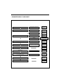
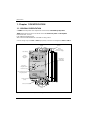
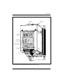
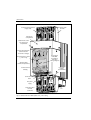
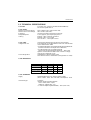
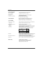
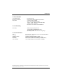
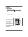
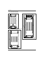
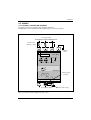
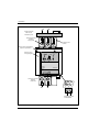
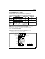
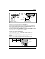
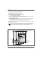
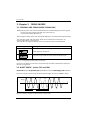
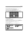
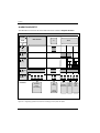
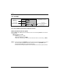
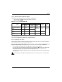
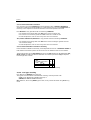
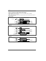
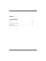
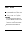
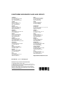
ε
7200A
Power
Thyristor Units
ENG
Two phase
load control
User Manual
7200A ADVANCED CONTROLLERS
THYRISTOR UNITS
CONTROLLING TWO PHASES
OF A THREE-PHASE LOAD
7000 SERIES
USER MANUAL
© Copyright Eurotherm Automation 2004
All rights reserved. All reproduction or transmission in any form whatsoever and using any procedure
(electronic or mechanical, including photocopying and recording) without written permission from
Eurotherm is strictly prohibited
Réf : HA176821 ENG - Issue 2.0 - 02 / 2005
i
COMMISSIONING FLOWCHART
Check characteritics
Characteristics correspond
to product code
Page 1-8
Mounting
DIN Rail
Page 2-3
Bulkhead Mounting
Page 2-4
Power
Page 2-7
Control
Page 2-8,2-9,2-10
Applying the control signal
ANA terminal Block
Page 2-9
Auxiliary Power Supply
If External Power Supply
(for electonics od/and fan)
Page 2-10
Wiring
Chapter 3
Check Firing
ii
Alarms signal
Diagnostic Alarm
Chapter 4
Adjust DLF alarm
(if conditionds met)
Bouton-poussoir CHK/SET
Chapter 4
Maintenance
Chapter 5
Thyristor Protection fuses
Chapter 5
7200A User Manual
Contents
CONTENTS
Page
Commissioning flowchart . . . . . . . . . . . . . . . . . . . . . . . . . . .ii
European Directives and applicable standards . . . . . . .iv
Chapter 1
Identification of power thyristor units . . . . . .1-1
Chapter 2
Installation . . . . . . . . . . . . . . . . . . . . . . . . . . . . .2-1
Chapter 3
Firing modes . . . . . . . . . . . . . . . . . . . . . . . . . . . .3-1
Chapter 4
Alarms . . . . . . . . . . . . . . . . . . . . . . . . . . . . . . . . .4-1
Chapter 5
Maintenance . . . . . . . . . . . . . . . . . . . . . . . . . . . .5-1
Index
. . . . . . . . . . . . . . . . . . . . . . . . . . . . . . . . . . . . . . .6-1
Eurotherm worlwide sales and services
. . . . . . . . . . . .7-1
PURPOSE OF MANUAL
This manual ( Issue 2.0 ) describes the Basic Version and all Options
for 7200A series three-phase power thyristor units.
Eurotherm’s policy of continuous product improvement and developement means that the specifications in this
document may be modified without prior notice.
7200A User Manual
iii
European directives and applicable standards
EUROPEAN DIRECTIVES AND APPLICABLE STANDARDS
COMPLIANCE WITH PRODUCT STANDARD
7200A products comply with the terms of product standard EN 60947-4-3
‘Contactors and motor-starters - AC semiconductor controllers and contactors for non-motor loads’.
CE LABELLING
7200A products installed and used in accordance with the user manual, bear CE labelling on
the basis of compliance with the essential requirements of the European Low Voltage
Directive 73/23 EEC dated 19 February 1973, modified by 93/68/EEC dated 22 July 1993 and
the Electromagnetic Compatibility Directive 89/336/EEC dated 3 May 1989 modified by
92/31/EEC dated 28 April 1992 and 93/68/EEC dated 22 July 1993.
SAFETY
The units have IP20 protection rating as defined by standard IEC 60529.
External wiring must comply with standards IEC 60364-4-43 and IEC 60943.
Copper cables and conductors must be used, rated to a temperature of 75°C (167°F).
ELECTROMAGNETIC COMPATIBILITY (EMC)
7200A products installed and used in accordance with the user manual, are designed for an
industrial environment and must not be used in the home.
IMMUNITY
The EMC immunity test standards required by the standard EN 60947-4-3
‘Contactors and motor-starters - AC semiconductor motor controllers and contactors for
non-motor loads’ are presented in table 1.
Test type
Electrostatic discharge
Radiated, radio frequency
electromagnetic field
Electrical fast transient / burst
Electrical surge
Conducted disturbances
Voltage dips, short interruptions
and voltage variation
Table 1.
Minimum levels
4 kV on contact; 8 kV in air
10 V/m 80 MHz ≤ f ≤ 1 GHz;
80% modulation 1 kHz sinusoidal
2 kV / 5 kHz
4 kV line to earth;
2 kV line to line
140 dBµV; 150 kHz ≤ f ≤ 80 MHz
EMC test standard
EN 61000-4-2
5 s interruptions
EN 61000-4-11
EN 61000-4-3
EN 61000-4-4
EN 61000-4-5
EN 61000-4-6
EMC immunity standards compliance
EMISSIONS
The EMC emissions test standards required by the standard EN 60947-4-3
‘Contactors and motor-starters - AC semiconductor motor controllers and contactors for
non-motor loads’ are presented in table 2.
Emission type
Firing mode
Test standard
Radiated at radio frequencies
All firing
CISPR 11 modes Class A
Conducted at radiofrequencies ‘Burst mode’ and ‘Single-cycle’ CISPR 11 Class A group 2
Table 2.
EMC emissions standards compliance
EMC GUIDE
To help you deal with installation-dependent electromagnetic interference effects,Eurotherm
provides an ‘Electromagnetic compatibility’ installation guide (ref. HA 025464 ENG) which
sets out best current practice regarding EMC.
CE CONFORMITY DECLARATION is available on request.
iv
7200A User Manual
Identification
1. Chapter 1
POWER THYRISTOR UNIT IDENTIFICATION
Contents
Page
1.1. General presentation . . . . . . . . . . . . . . . . . . . . . . . . . . . . . . . . . . . .1-2
1.2. Technical specifications . . . . . . . . . . . . . . . . . . . . . . . . . . . . . . . . .1-5
1.2.1. Use . . . . . . . . . . . . . . . . . . . . . . . . . . . . . . . . . . . . . . . . . . . . . . .1-5
1.2.2. Power . . . . . . . . . . . . . . . . . . . . . . . . . . . . . . . . . . . . . . . . . . . .1-5
1.2.3. Load . . . . . . . . . . . . . . . . . . . . . . . . . . . . . . . . . . . . . . . . . . . . .1-5
1.2.4. Dimensions . . . . . . . . . . . . . . . . . . . . . . . . . . . . . . . . . . . . . . .1-5
1.2.5. Command . . . . . . . . . . . . . . . . . . . . . . . . . . . . . . . . . . . . . . . . .1-5
1.2.6. Firing modes . . . . . . . . . . . . . . . . . . . . . . . . . . . . . . . . . . . . . .1-6
1.2.7. Control . . . . . . . . . . . . . . . . . . . . . . . . . . . . . . . . . . . . . . . . . . .1-6
1.2.8. Indication . . . . . . . . . . . . . . . . . . . . . . . . . . . . . . . . . . . . . . . . .1-6
1.2.9. Alarms . . . . . . . . . . . . . . . . . . . . . . . . . . . . . . . . . . . . . . . . . . .1-6
1.2.10. Protection . . . . . . . . . . . . . . . . . . . . . . . . . . . . . . . . . . . . . . . .1-7
1.2.11. Mounting . . . . . . . . . . . . . . . . . . . . . . . . . . . . . . . . . . . . . . . .1-7
1.2.12. Environment . . . . . . . . . . . . . . . . . . . . . . . . . . . . . . . . . . . . .1-7
1.3. Coding . . . . . . . . . . . . . . . . . . . . . . . . . . . . . . . . . . . . . . . . . . . . . . . .1-8
7200A User Manual
1-1
Identification
1. Chapter 1 IDENTIFICATION
1.1. GENERAL PRESENTATION
A 7200A series thyristor unit comprise of two channel, controlled by thyristors.
7200A series thyristor units are used to control the electrical power of three-phase
industrial loads ; such as :
Low coefficient resistive loads
Short wave infrared elements for units with a rating ≤ 100 A
Current ratings vary from 16 A to 200 A (per phase), at line-to-line voltages from 200 V to 500 V
Power terminals
(supply)
User labelling
Internal
power wiring
diagram
ε
Protective earth
terminal
Ratings
(nominal current
and nominal voltage)
7200A
EUROTHERM
63 A / 500 V
1/L1
3/L2
5/L3
2/T1
4/T2
6/T3
PE
DLF option :
CHK/SET
push button
GRF
CHK
SET
DLF option :
Diagnostic alarm
DLF
Electronics supply
HEAT
ON
ALR
EN 60947-4-3
0VA RI
31 32
1a 1b
73 74
5VA
33
Aux
1
ANA
Zero crossing firing mode :
Firing request LED
230
16 17
N
18
Control terminal
pinouts
Control connector
Power terminals
(load)
Fig 1.1. General view of a 7200A power unit ratings from 16 A to 63 A
1-2
7200A User Manual
Identification
Power terminals
(supply)
ε
Internal
power wiring
diagram
Protective earth
terminal
7200A
EUROTHERM
80 A / 500 V
PE
1/L1
3/L2
5/L3
2/T1
4/T2
6/T3
GRF
DLF option :
Diagnostic alarm
DLF
Electronics supply
HEAT
CHK
SET
ON
EN 60947-4-3
0VA RI
31 32
1a 1b
73 74
5VA
33
Aux
1
ANA
ALR
Zero crossing firing mode :
Firing request LED
230
16 17
N
18
Control terminal
pinouts
Control connector
Power terminals
(load)
Fig 1.2. General view of a 7200A power unit ratings from 80 A to 100 A
7200A User Manual
1-3
Identification
Protective earth
terminal
Controlled phase terminal
(supply side)
3/L2
1/L1
internal fuse
compartment
2 attachment screws
for internal fuse
compartment
Internal wiring diagram
(internal fuse for
125 to 200 A ratings)
ε EUR OTH ERM
Over-temperature Alarm
( ≥ 125 A only)
720 0A
125 A / 500 V
1/L1
3/L1
2/T1
4/T1
PE
DLF Option:
CHK/SET
push-button:
DLF alarm
setting /diagnosis
T°
GRF
Signalling LEDs
(alarms and operation)
CHK
SET
DLF
ON
EN 60947-4-3
0VA RI
31 32
Fuse blown
contact
(code MSFU)
1a 1b
73 74
5VA
33
230
N
16 17 18
MSF
A/F
ANA
Control terminal
labelling
ALR
HEAT
3a 3b
75 76
Control terminal
block
Not
used
FAn power
supply
2/T1
4/T2
Controlled phase
terminal
(load side)
Fan
Fig 1.3. General view of a 7200A power unit ≥ 125 A rating
1-4
7200A User Manual
Identification
1.2. TECHNICAL SPECIFICATIONS
1.2.1 Use
Thyristor unit, variant 4 (see Standard EN 60947-4-3)
for uninterrupted service.
1.2.2. Power
Nominal current per phase
Nominal line to line voltage
Frequency
Dissipated power
Cooling
16 A to 200 A at 45 °C (see product code)
200 V to 500 V (see code).
Use from 47 to 63 Hz (automatic matching)
1,3 W (approx.) per amp and per phase
Ratings ≤ 100 A : Natural convection
Ratings ≥ 125 A : Fan-cooled.
115 V or 230 V ; consumption 10 VA.
1.2.3. Load
Industrial three-phase load, three-wire configuration.
The categories of use applicable for each unit are indicated
on the identification label.
• AC-51 Non-inductive or low inductance loads, furnace resistances.
(resistive load with low temperature coefficient)
• AC-55b Switching of incandescent lamps
(Short wave infrared elements, SWIR) for ≤ 100 A units
Options must be fitted to 7200A units in order to comply
with certain categories of use.
Independant of phase rotation order
Star without neutral, closed delta. (Configuration on order)
Categories of use
Load configuration
1.2.4. Dimensions
Rating
Height
Width
Depth (mm)
Basic
DLF
16 A à 63 A 220 mm 96 mm 214
264
80 A à 100 A 305 mm 144 mm 372
372
125 A à 200 A 495 mm 144 mm 372
372
1.2.5. Command
Supply
Self-powered from line or external power supply
(115 V or 230 V +10%; -15%, see code). Consumption : 10 VA
Command type
Analogue
• Either remote analogue setpoint :
0-5V or 0-10V (100 kΩ input)
0-20mA or 4-20mA (250 Ω i/p)
• or manual setpoint (potentiometer) : 0-5V (2 mA max).
7200A User Manual
1-5
Identification
1.2.6. Firing modes
Zero crossing firing
• ‘Burst mode’, base time : 16 or 64 cycles
• ‘Single-cycle’, base time : 1 cycle
1.2.7. Control
Parameters
Linearity and Stability
1.2.8. Indication
• Standard (on balanced three-phase supply) :
Load voltage squared (V2)
Better than ±2% of full scale
(on balanced three-phase supply)
Electronic supply present Green ‘ON’ LED and
supply fault detection : ‘ON LED flashing’
Thyristor firing request : Green ‘HEAT’ LED
1.2.9. ALARMS
Serious alarms (GRF)
Signalling
Total load failure and thyristor short circuit detection.
Red ‘GRF’ LED and alarm relay contact
Diagnostic alarm (DLF)
Signalling
Settings
Partial Load Falure detection.
Orange ‘DLF LED and alarm relay contact’.
Monitoring diagnosis, alarm adjustment and resetting
using push button on front pannel.
Detects the failure of at least one heating element for
several identical elements, connected in parallel.
Sensitivity
Firing
mode
Extension
Over-temperature alarm
Signalling
Alarm relay
1-6
Load
confuguration
3D 3S
FC1
1/2 1/3
C16, C64
1/3 1/4
The DLF option includes Serious alarm monitoring (GRF)
Partial Load Failure detection for SWIR loads is only
avalable when using FC1 Burst firing mode
For all fan-cooled units (≥ 125 A, available later),
the unit cuts out if the temperature threshold is exceeded.
Red ‘T °’ LED Alarm relay contact with any alarm.
Available with alarm options.
The relay contact (0,25 A/230 Vac; 32 Vdc) is
either open on alarm or closed on alarm
depending on the product code.
7200A User Manual
Identification
1.2.10. Protection
Co-ordination type
Electrical protection
Thyristors
For short circuits.
IP20 without adding additional protection.
Varistor and RC snubber.
Quick-acting three-phase fuses :
• rating ≤ 100 A : external (order separately)
• rating ≥ 125 A : internal.
No fuse for short wave infrared elements
1.2.11. Mounting
Mounting
Attachment plate fixed to unit :
• On symmetrical EN50022 DIN rail or
• bulkhead mounting
(for ratings ≥ 80 A : bulkhead mounting only).
1.2.12. Environment
Use
Storage
Isolation voltage
Pollution
Humidity
Over-Voltage
From 0 to 45 °C at nominal current, max. altitude 1000 m
From -10 °C to 70 °C.
Assigned isolation voltage Vi = 500 V.
Degree 2 acceptable (as defined by IEC 60664).
RH from 5% to 95% non-condensing, non-streaming.
Over-voltage category II (as defined by IEC 60664)
Eurotherm’s policy of continuous product improvement and development means that the specifications in this document
may be modified without prior notice.
7200A User Manual
1-7
Identification
1.3. Codification
Ratings
1. Nominal current per phase
16 amps
25 amps
40 amps
63 amps
80 amps
100 amps
125 amps
160 amps
200 amps
Code
16A
25A
40A
63A
80A
100A
125A
160A
200A
2. Nominal line to line voltage
200 volts
230 volts
277 volts
400 volts
460 volts
480 volts
500 volts
Code
200V
230V
277V
400V
460V
480V
500V
3. Power supply for electronics
Self-powered
External 115 V supply
Code
SELF
115V
External 230 V supply
230V
4. Fan power supply
≤ 100A : No fan
≥ 125A : - 115 V fan and
- 230 V fan and
Code
XXXX
115V
230V
5. Load configuration
Star without neutral
Closed delta
Code
3S
3D
Basic Selection
9. Manual language
Code
French
English
German *
FRA
ENG
GER
10. Selected options
Code
Without options : V2 control and
End of code
NONE
With options:
Selection of options
YES
Control and Alarms options
11. Type 1 Alarms
Code
Partial Load Failure and
Serious Alarms
DLF
No Alarms
NONE
12. Load Type
Code
With DLF Option :
Short Infrared (witn FC1 only)
Low temperature coefficientloads
SWIR
LTCL
Without DLF option or
High temperature coefficient loads
XXXX
13. Alarm relay contact
Code
With alarm otpion : closed on alarm
open on alarm
NC
NO
Without alarm option
XX
Certification et warranty extension
6. Thyristor fuses
Code
14. NONE
Fuses without fuse blown microswitch
Fuses with fuse blown microswitch
FUSE
MSFU
15. Certification
Code
Without fuses (SWIR)
NONE
Without certificate
With certificate
NONE
CFMC
7. Firing mode
Code
‘Burst mode’ :
base time 16 cycles
base time 64 cycles
‘Single-cycle’ : base time 1 cycle
C16
C64
FC1
8. Input
Code
Analogue signal :
current from 0 mA to 20 mA
current from 4 mA to 20 mA
voltage from 0 V to 5 V
voltage from 0 V to 10 V
0mA20
4mA20
0V5
0V10
1-8
16. Warranty extension
Without warranty extension
Warranty extended to 5 years
Code
NONE
WL005
7200A User Manual
Installation
2. Chapter 2
INSTALLATION
Contents
Page
2.1. Safety during installation . . . . . . . . . . . . . . . . . . . . . . . . . . . . . . . .2-2
2.2. Mounting . . . . . . . . . . . . . . . . . . . . . . . . . . . . . . . . . . . . . . . . . . . . . .2-3
2.2.1. Types of mounting . . . . . . . . . . . . . . . . . . . . . . . . . . . . . . . . .2-3
2.2.2. Attachement plates . . . . . . . . . . . . . . . . . . . . . . . . . . . . . . . . .2-3
2.2.3. Mounting on DIN rails . . . . . . . . . . . . . . . . . . . . . . . . . . . . . .2-3
2.2.4. Bulkhead mounting . . . . . . . . . . . . . . . . . . . . . . . . . . . . . . . .2-4
2.3. Wiring . . . . . . . . . . . . . . . . . . . . . . . . . . . . . . . . . . . . . . . . . . . . . . . .2-5
2.3.1. General connection diagram . . . . . . . . . . . . . . . . . . . . . . . . .2-5
2.3.2. Power connections . . . . . . . . . . . . . . . . . . . . . . . . . . . . . . . . .2-7
2.3.2.1. General . . . . . . . . . . . . . . . . . . . . . . . . . . . . . . . . . . . . .2-7
2.3.2.2. Three-phase load configuration diagram . . . . . . . . .2-7
2.3.3. Control connections . . . . . . . . . . . . . . . . . . . . . . . . . . . . . . . .2-8
2.3.3.1. Control terminal blocks . . . . . . . . . . . . . . . . . . . . . . .2-8
2.3.3.2. Control signal . . . . . . . . . . . . . . . . . . . . . . . . . . . . . . . .2-9
2.4. Alarm relay contact . . . . . . . . . . . . . . . . . . . . . . . . . . . . . . . . . . . . .2-9
2.5. External power supply terminal block . . . . . . . . . . . . . . . . . . . . .2-10
2.5.1. Power supply for electronics . . . . . . . . . . . . . . . . . . . . . . . . .2-10
2.5.2. Power supply for the fan . . . . . . . . . . . . . . . . . . . . . . . . . . . .2-10
2.5.3. Power supply for electronics and fan . . . . . . . . . . . . . . . . . .2-11
7200A User Manual
2-1
Installation
2. Chapter 2
INSTALLATION
2.1. SAFETY DURING INSTALLATION (MOUNTING AND WIRING)
Danger!
• 7200A power thyristor units must be installed and wired by qualified staff
authorised to work on low voltage industrial electrical facilities.
• Units must be installed in a fan-cooled cabinet, to ensure that condensation and
pollution are excluded, with a class of at least 2 according to IEC 60664.
We recommend fitting fan-cooled cabinets with a fan failure detection device or
a thermal safety cut-out.
The cabinet must be closed and connected to the protective earth according to
IEC 60364 or applicable national standards.
Important!
!
• Units must be mounted with the heatsink positioned vertically, and with no obstructions above or below the unit which could reduce or hamper air flow.
If several units are fitted in the same cabinet, arrange them such that air from one
unit is not drawn in by the unit above.
The ambient temperature beneath the unit must not exceed 45°C.
Leave a gap of at least 10 mm between adjacent units.
Important!
!
• Nominal currents correspond to use at ambient temperatures of no more than
45°C. Overheating may cause incorrect operation and may even lead to components being damaged.
Danger!
• It is the user’s responsibility to wire and protect the facility according to best
practice and applicable standards.
A suitable device, ensuring that the unit can be electrically isolated from the supply, must be installed upline to enable work to be performed safely.
Conductor cross-sections should comply with IEC 60943.
Only use copper cables and wires rated for use at 75 °C.
• Before connecting or disconnecting the unit check that power and control cables
and leads are isolated from voltage sources.
The protective earth must be connected before any other connections are made
and should be the last cable to be disconnected.
The protective earth connection terminal is marked with the symbol:
To ensure the electrical safety and the earth protection continuity, the front
pannel screws must be screwed in correctly to the coupling torque of 0.5 Nm
!
Important!
• To ensure that 7200A power thyristor units comply with Electromagnetic
Compatibility requirements, ensure that the panel or DIN rail to which they are
attached is correctly grounded.
The ground connection, designed to ensure ground continuity, is not in any way
a substitute for the protective earth connection.
2-2
7200A User Manual
Installation
2.2. MOUNTING
2.2.1. TYPES OF MOUNTING
• DIN rail mounting and bulkhead mounting - 16 A to 63 A only
• Bulkhead mounting with screws ≥ 80 A
DIN rail mounting (≤ 63 A only)
Attachment plate
DIN rail
Two horizontal
Two symmetrical
plates
rails EN 50022
Bulkhead mounting
Attachment plate
Screws
Two horizontal
4 × M4 (≤ 63 A)
plates
4 x M6 (≥ 80 A)
Table 2-1 Attachment details for both mounting types
2.2.2. ATTACHMENT PLATES
Two factory-fitted attachment plates on the rear of the 7200A thyristor units are used:
• to clip the unit to a DIN rail, or
• to screw the unit to a bulkhead.
Each attachment plate has: • attachment holes for bulkhead mounting, and
• two fixed hooks and two mobile hooks for clipping to a DIN rail.
(the mobile hooks are moved using a catch and spring).
2.2.3. MOUNTING ON DIN RAILS
To remove the unit:
• move the mobile hooks downward by
pulling the catch on the bottom
attachment plate
• unclip the unit from the rail.
7200A User Manual
Attachment
hooks
220
125
For DIN rail mounting:
• fix two symmetric DIN rails (for units
rated 16 A to 63 A) in accordance with
the unit dimensions and safety
recommendations.
• bring the unit up against the top rail,
engaging the two fixed hooks on the
top attachment plate
• push the unit against the rail
• clip the unit onto the bottom rail
using the mobile hooks on the bottom
attachment plate, ensuring that they
are properly engaged.
Upper
attachment
plate
EN50022
DIN Rails
Mobile attachment
hooks
Catch to move
hooks downwards
Lower
attachment
plate
Figure 2-1 Rails DIN attaching.
2-3
Installation
2.2.4. BULKHEAD MOUNTING
For 2
M4 screws
96
144
80
426.7
498
399.7
210
220
For 2 M6
screws
For 2
M4 screws
Figure 2-2 Bulkhead mounting - 16 A to 63 A units
144
For 2
M6 screws
275
305
124
124
For 2 M6
screws
Figure 2-4 Bulkhead mounting - ≥ 125 A units
For 2
M6 screws
Figure 2-3 Bulkhead mounting - 80 A to 100 A units
2-4
7200A User Manual
Installation
2.3. WIRING
2.3.1. GENERAL CONNECTION DIAGRAM
The general connection diagram shows the power terminals
(independently of the three-phase load configuration) and control connectors.
To supply network
Protection and cut)out installed by user
Thyristor fuses
(External ≤ 100 A)
ε
EUROTHERM
7200A
Protective
Earth
63 A / 500 V
1/L1
3/L2
5/L3
2/T1
4/T2
6/T3
PE
ON
0VA RI
31 32
EN 60947-4-3
Analogue signal
connector
5VA
33
Aux
1
ANA
HEAT
230
16 17
N
18
To three-phase load :
Auxiliary power supply
Figure 2-5 General connection diagram for units ≤ 100 A
7200A User Manual
2-5
Installation
L1
L2
Supply protection
and cut-out.
Installed by user
Controlled channel
terminal
(supply side)
1/L1
3/L2
Protective earth
terminal
Internal fuse compartment
(thyristor protection)
Internal power
wiring diagram
ε EUROTHERM
7200A
200 A / 500 V
1/L1
3/L2
2/T1
4/T2
PE
ON
5VA
33
230
N
16 17 18
MSF
0VA RI
31 32
EN 60947-4-3
A/F
ANA
HEAT
3a 3b
Controlled channel
terminal
(load side)
2/T1
4/T2
MSF
75 76
3a 3b
75 76
Internal fuse blown
contact(MSFU)
Figure 2-6 General connection diagram for units with rating ≥ 125 A
2-6
7200A User Manual
Installation
2.3.2. POWER CONNECTIONS
2.3.2.1. General (Ratings from 16 A to 200 A)
7200A power thyristor units comprise two channels controlled by thyristors.
Terminals 1/L1, 3/L2 and 5/L3 must be wired to the three-phase supply network.
Terminals 2/T1, 4/T2 and 6/T3 must be wired to the three-phase load.
The protective earth terminal PE (earth symbol) must be wired to the protective earth.
Ratings A
16
40
80
à 25
à 63
à 100
Ratings
A
125
160
200
Terminal Capacity
mm2
AWG
2,5 à 6
13 à 9
6
à 16
9 à 5
16 à 35
5 à 2
Clamping torque
Nm
1,2
1,8
3,8
Stripping length
mm
13
13
20
Terminal Capacity
mm2
AWG
50 à 120
0
70 à 120
00
95 à 120
000
Clamping torque
Nm
Crimp eyelet
16,4 (or 28,8)
M10 nut (17 wrench)
to attach eyelet
and terminal
Table 2-2 Power wiring details for ratings from 16 to 200 A
ø 10 (ou ø 12)
NOTE : Conductor cross-sections should comply with IEC 60943.
Power connections to the thyristor unit depend on the load configuration scheme.
The following two configuration schemes may be used for three-phase loads:
2.3.2.2. Three-phase load coupling
Power connections to the unit depend on the load configuration.
The following two configuration schemes may be used for three-phase loads:
• star without neutral (3 connection wires, code 3S),
• closed delta (3 connection wires, code 3D)
Three-phase supply
Protection and cut-out installed by user
L1
L2
L3
Thyristor fuses
3 power terminals
(supply side)
ε
EUROTHERM
Protective earth
terminal
7200A
63 A / 500 V
EN 60947-4-3
Internal
power wiring
diagram
1/L1
3/L2
5/L3
4/T2
6/T3
2/T1
PE
ON
ANA
HEAT
Analogue input
connector
0VA RI
31 32
5VA
33
3 power terminals
(load side)
OR
Three-phase load
(star without neutral)
Three-phase load
(closed delta)
Figure 2-7 Connecting a three-phase load using star without neutral OR closed delta configuration
7200A User Manual
2-7
Installation
2.3.3. CONTROL CONNECTIONS
Terminal blocks on the underside of the 7200A power thyristor unit are used to connect:
• the control signals (analogue)
• the auxiliary or electronics supply and the neutral
• alarm relay and acknowledgement contacts
The wires used should be stripped for a length of 6 to 7 mm.
2.3.3.1.Control terminal blocks
The control terminal blocks are plug-in screw connectors.
The terminal blocks available depend on the power thyristor unit version and the selected
options in the product code.
The terminal names and numbers are marked on the front panel for available terminal
blocks.
The table below gives details of all terminals and terminal blocks.
Version
Basic or
Options
Options
Alarms
High
Current
≥ 125 A
Terminal
block name
ANA
A/F
(except
SELF)
ALR
MSF
No.
31
32
33
16
17
18
71
72
73
74
75
76
Terminal description
Name
Purpose
0VA
RI
5VA
230
115
0V
1a
1b
2a
2b
3a
3b
0 V for analogue signals
‘+’ for analogue signals
5 V user output
230 V aux. supply
115 V aux. supply
Neutral or second phase
Alarm relay
contact (code NC)
Alarm relay
contact (code NO)
Fuse with
micro-switch contact
Terminal
capacity
mm2 AWG
Torque
1.5
16
0.5
2.5
14
0.7
2.5
14
0.7
2.5
14
0.7
Nm
Table 2-3 Description of control terminal blocks
2-8
7200A User Manual
Installation
2.3.3.2. Control signal
Analogue
control
signal
connector
0VA RI
31 32
5VA
33
b)
ANA
ANA
a)
0V
0VA RI
31 32
5VA
33
0%
0V
10 kΩ
Potentiometer
+ Control
signal
100%
a) external signal, e.g. from
Eurotherm series 2000 controller
+5 V internal
b) manual command from
external potentiometer
Figure 2-8 Control signal connection (self-powered unit, base version)
The analogue control signal terminal block is labelled ANA.IN.
The input available corresponds to the input type selected in the product code (specified
range of voltage or current). The signal must be connected between terminals 32 and 31.
The ‘+’ of the control signal must be connected to terminal 32 (labelled RI).
A typical external signal connection is shown on figure 2-8a.
Figure 2-8b shows how to use the internal 5 V voltage (terminal 33 labelled 5VA) for manual
control with an external 10 kΩ potentiometer. This voltage (5 V Analogue) is intended for
manual control, which is only possible with input code 0V5.
2.4. Alarm relay contact (alarm option)
If one of the alarm options is fitted, an alarm relay contact is available on the
‘ALR’ terminal block (see figure 2-9).
The type of contact (closed or open on alarm) is determined by the product code.
Contact switching capacity: 0.25 A (maximum 250 Vac or 30 Vdc).
Important!
The type of contact (closed or open on alarm) determines the terminal numbers
in accordance with standard EN 60947-4-3.
Contact type
Code Terminal
number
Terminal labelling
(e.g. contact open
on alarm)
ON
HEAT
71 and 72
73 and 74
ALR
NC
NO
AN
A
Closed on alarm
Open on alarm
1a 1b
73 74
0VA RI 5VA
31 32 33
Alarm contact
connector
Alarm relay contact
Figure 2-9 Typical alarm relay contact connections
7200A User Manual
2-9
Installation
2.5. External power supply terminal block
Power supply for electronics and fan (A/F)
• The power supply for the electronics may be either :
• internal (self-powered, code SELF) or
• external, 115 V or 230 V depending on the product code
Only one terminal (16 for 230 V or 17 for 115 V) is available depending on the product code.
• The power supply for the fan :
For units from 125 A and above, the fan must be powered on with an external power
supply115 V or 230 V depending on the product code. The same code A/F is used.
(terminal 16 for 230 V or 17 for 115 V depending on the product code)
It also possible to combine the power supply for electronics and the power supply fo the fan,
115 V or 230 V(both the same).
!
In the case of an external power supply for electronics or when combining with
the fan power supply, it is necessary to have the power supply in phase or phase
opposition with the the voltage between the controlled phases of the unit.
Protection / Cut-off installed by user
L1
L2
Supply Network
L3
ε
EUROTHERM
7200A
63 A / 500 V
EN 60947-4-3
1/L1
3/L2
5/L3
2/T1
4/T2
6/T3
PE
1 A Fuse
ON
230 V
0VA RI 5VA
31 32 33
A/F
AN
A
HEAT
230
16 17
0V
18
Power supply for
electronics and fan
terminal block
Figure 2-10 Wiring example for the external auxiliary power supply for electronics and the fan (code 230V)
2-10
7200A User Manual
Firing modes
3. Chapter 3
FIRING MODES
Contents
Page
3.1. General and firing mode signalling . . . . . . . . . . . . . . . . . . . . . . . .3-2
3.2. Burst mode (codes C16 and C64) . . . . . . . . . . . . . . . . . . . . . . . . . . .3-2
3.3. Single-cycle (code FC1) . . . . . . . . . . . . . . . . . . . . . . . . . . . . . . . . . . .3-4
7200A User Manual
3-1
Firing modes
3. Chapter 3
FIRING MODES
3.1. GENERAL AND FIRING MODE SIGNALLING
7200A power thyristor units can be controlled with one of the following thyristor firing types:
• a series of supply voltage cycles with zero crossing firing
(‘Burst mode’, codes C16, C64, FC1)
The firing type is shown on the unit’s front panel (table 3-1) in accordance with the product code.
Two indicators (green ‘ON’ and ‘HEAT’ LEDs) are included on the front panel in all
versions, either basic or with options.
The indicators correspond to the thyristor firing mode as shown in the table below.
LED labelling
ON
HEAT
Signalling
Power supply for electronics.
Thyristor firing request in ‘Burst mode’ and ‘Single-cycle’
Table 3-1 Firing modes and base LEDs on front panel
During normal operation with zero-crossing switching, the ‘HEAT’ LED flashes to match the
thyristor firing periods.
3.2. BURST MODE (codes C16 and C64)
‘Burst mode’ firing is a proportional cycle which delivers a series of whole supply cycles to the load.
Thyristor firing and cut-off is synchronised with the supply and occurs at zero crossing.
Load
voltage
t
TNC
TC
TM
Figure 3-1 Thyristor firing for one of the phases, in ‘Burst mode’
3-2
7200A User Manual
Firing modes
Thyristor firing in ‘Burst mode’ can be described by the firing time (TC) , non-firing
time (TNF) and modulation time (TM) ; where TM = TC + TNC
The power delivered to the load is defined by the duty ratio η = TC / TM
Firing in ‘Burst mode’ is defined by the Base Cycle Time (TB).
The Base Cycle Time is equal to the number of cycles firing at 50% of the duty ratio
(or 50% of the power supplied to the load): TB = Tc = TNC.
The Base Cycle time is equal to 16 cycles for code C16 and 64 cycles for code C64.
Modulation time
TM
10 TB
8 TB
6 TB
4 TB
TC = TNC = TB
2 TB
TB
0
25 %
50 %
75 %
Duty ratio η
100 %
Figure 3-2 ‘Burst mode’ modulation time depending on setpoint
The control system adjusts the modulation time to retain the same precision for all duty
ratios η (power requested).
3.3. SINGLE-CYCLE (code FC1)
‘Burst mode’ firing with a single firing or non-firing cycle is known as ‘Single-cycle’.
For example, with a setpoint of 50% (corresponding to a duty ratio η = 50%) the modulation
comprises 1 firing cycle and 1 non-firing cycle.
For duty ratios η < 50% the firing time remains unchanged (1 cycle) and
the non-firing time increases.
For duty ratios η > 50% the non-firing time remains unchanged (1 cycle) and
the firing time increases.
25%
power
75%
power
t
TNC
TC
TNC
TC
TNC = 3 TC
TM
TM
50%
power
t
TC = 3 TNC
t
TNC
TC
TM
TNC = TC = TB
Figure 3-5 Typical firing in ‘Single-cycle’ mode for various duty ratios
7200A User Manual
3-3
Firing modes
3-4
7200A User Manual
Alarms
4. Chapter 4
ALARMS
Contents
Page
Alarm diagnostic . . . . . . . . . . . . . . . . . . . . . . . . . . . . . . . . . . . . . . . . . . .4-2
4.1. Safety mechanisms . . . . . . . . . . . . . . . . . . . . . . . . . . . . . . . . . . . . . .4-3
4.2. Alarm strategy . . . . . . . . . . . . . . . . . . . . . . . . . . . . . . . . . . . . . . . . .4-3
4.2.1. Types of alarm . . . . . . . . . . . . . . . . . . . . . . . . . . . . . . . . . . . . .4-2
4.2.2. Alarm actions . . . . . . . . . . . . . . . . . . . . . . . . . . . . . . . . . . . . . .4-2
4.2.2.1. Firing cut-off . . . . . . . . . . . . . . . . . . . . . . . . . . . . . . .4-2
4.2.2.2. Signalling . . . . . . . . . . . . . . . . . . . . . . . . . . . . . . . . .4-2
4.2.2.3. Alarm priority . . . . . . . . . . . . . . . . . . . . . . . . . . . . .4-2
4.2.2.4. Alarm relay . . . . . . . . . . . . . . . . . . . . . . . . . . . . . . . . .4-2
4.2.2.5. Memorisation . . . . . . . . . . . . . . . . . . . . . . . . . . . . . .4-3
4.3. Type 1 alarms . . . . . . . . . . . . . . . . . . . . . . . . . . . . . . . . . . . . . . . . . .4-4
4.3.1. DLF option (Load failure diagnostic alarm) . . . . . . . . . . . .4-4
4.3.1.1. Alarm actions with DLF option . . . . . . . . . . . . . . . . .4-5
4.3.2. PLF diagnostic detection specifications . . . . . . . . . . . . . . .4-5
4.3.2.1. Setting the DLF alarm . . . . . . . . . . . . . . . . . . . . . . . .4-5
4.3.2.2. PLF detection conditions . . . . . . . . . . . . . . . . . . . . . .4-6
4.3.2.3. PLF detection sensitivity . . . . . . . . . . . . . . . . . . . . . .4-6
4.3.2.4. Load type matching . . . . . . . . . . . . . . . . . . . . . . . . . . .4-6
4.3.2.5. Signalling of channel for load fault . . . . . . . . . . . . .4-7
4.3.2.5.1. Disabling alarms for load failure signalling . .4-7
4.3.2.5.2. Functions of DLF alarm push button . . . . . . .4-8
7200A User Manual
4-1
Alarms
ALARM DIAGNOSTIC
The table below summarises all status LED information needed to diagnose the fault.
OPTIONS
Basic Version
LEDs
(Front panel)
T°
DLF
T°
≥ 125 A
Red
GRF
Red
DLF
Orange
ON
green
HEAT
Green
DIAGNOSIS:
No Alarm
Overheating
Firing :
Zero crossing
Thyristor
short-circuit
Total
Load
Failure
Partial
Load
Failure
Firing
STOPPED
Figure 4-1 Diagnosing operation and alarms according to front panel LED status
4-2
7200A User Manual
Alarms
4. Chapter 4
ALARMS (Options)
4.1. SAFETY MECHANISMS
The alarms on the 7200A protect the thyristors and the load against certain types of abnormal
operation and provide the user with information about the type of fault.
• Alarms are not under any circumstances a replacement for personnel protection.
• The user is responsible for installing independent safety mechanisms which must
be inspected regularly. Given the value of the equipment controlled by the 7200A,
Danger this is strongly recommended.
Eurotherm can supply various types of suitable alarm detector.
4.2. ALARM STRATEGY
4.2.1. TYPES OF ALARM
Two types of alarm are available as options :
• monitoring of load and thyristors
4.2.2. ALARM ACTIONS
4.2.2.1. Firing cut-off
When ‘Overheating’ fault is detected (for current ratings ≥ 125 A only)
4.2.2.2. Signalling
All faults detected are signalled by illuminating or flashing the corresponding LEDs.
The LEDs are located on the front panel of the thyristor units beneath the product code.
The LEDs present are determined by the option selected.
4.2.2.3. Alarm priority
Only one alarm is signalled if several faults occur simultaneously. Thermal faults and
thyristor short-circuits take priority over load fault display.
4.2.2.4. Alarm relay
All alarms change the position of the Alarm relay contact. Depending on the product code this
contact may be open on alarm (code NO) or closed on alarm (code NC). The alarm contact
switching capacity is 0.25 A (230 Vac or 32 Vdc).
4.2.2.5. Memorisation
Alarms (except Neutral cut-off) are not memorised. After an alarm has been detected, and
once the fault conditions have cleared, signalling for these alarms (LED and relay) returns to
the non-alarm position.
Thyristor short-circuit and neutral cut-off require repairs.
7200A User Manual
4-3
Alarms
4.3. ALARMS
Red LED :
'Serious faults'
Orange LED :
'Partial Load Failure'
Red LED :
'Overheating' (≥125 A)
T°
GR F
DLF
CHK
SET
DLF alarm
adjustment and diagnostic
push button
Figure 4-2 Layout of front panel LEDs
4.3.1. DLF OPTION (Load failure Diagnostic alarm)
Alarms monitored with DLF option
With the ‘DLF’ option (Diagnostic Load Failure alarm) the following faults are monitored
and diagnosed:
• Partial Load Failure, PLF
• Serious faults
• Total Load Failure, TLF
• Thyristor Short Circuit, THSC
• Thyristor overheating, T° (only for fan-cooled units with current rating ≥ 125 A).
Note: •
Thermal faults are signalled by the ‘T°’ LED if one of the alarm options or one of
the control options (except V2 and OL) is fitted. The unit is protected against
thermal faults whether or not they are signalled.
• Thermal faults are signalled by the alarm relay if one of the alarm options is fitted.
4-4
7200A User Manual
Alarms
4.3.1.1. Alarm actions with DLF option
The detection of a fault (PLF or serious alarm) is signalled by :
• the corresponding LED on the front pannel of the unit
• the alrm relay contact
Note : DLF alarms are not memorised.
Fault
Partial load failure
(PLF)
Total load failure
(TLF)
Thyristor short-circuit
(THSC)
Overheating (T°)
Table 4-1
LED states
‘DLF’
orange
‘T°’
red
‘GRF’
red
Off
Off
Flashing
Off
On
Flashing
Off
On
On
Off
‘HEAT’
green
Firing
stopped
On or
Flashing
No
Off
Off
No
Off
Off
Yes
Typical
reaction
time
1 s to 13 s
LEDs for fault
4.3.2. PLF Diagnostic detection specifications
4.3.3.1. Setting the DLF alarm
Adjusting PLF detection involves calculating and storing the value of the reference impedance
from the measured rms current and voltage values.
This can be set using the push button on the front panel. The PLF detection setting can only be
adjusted automatically (reference impedance recalculated) in the following conditions:
• rms voltage across load greater than 40% of the unit’s nominal voltage
• rms unit’s line currents (going through the unit) are greater than 30% of the unit rated current
• no over-temperature, over-current or thyristor short-circuit faults or type 3 alarms.
• Each time PLF setting is required, the load must be balanced
• In order to guarantee the sansilbility full scale, settings must be done at the load’s nominal
temperature.
!
The PLF detection settings should be adjusted each time the thyristor unit is recalibrated.
7200A User Manual
4-5
Alarms
4.3.2.2. Partial load failure detection
PLF monitoring involves comparing the load impedance with a reference impedance
stored during setting (the load impedance is calculated from the rms values measured continuously). This comparison allows the detection of the load impedance increase.
PLF detection is only possible under the following conditions:
• rms voltage across load greater than 40% of the nominal voltage, and
• rms unit’s line currents are greater than 5% of the unit’s rated current.
• no over-temperature, over-current or thyristor short-circuit faults.
TLF (Total Load Failure) detection is only possible under the following conditions :
• rms voltage across load greater than 40% of the nominal voltage or greater than the
unit nominal voltage.
• no over-temperature, over-current or thyristor short-circuit faults.
4.3.2.3. Partial load failure detection sensitivity
Partial load failure detection sensitivity can be expressed in terms of a maximum number of
load elements connected in parallel for which the unit can detect the failure of one element.
The DLF diagnostic alarm guarantees that failure of One element will be detected for two,
three or four (see table 4-2) identical elements connected in parallel for any three-phase
load configuration scheme.
Firing
mode
Load
configuration
3D 3S
FC1
1/2 1/3
C16, C64
1/3 1/4
Table 4-2 Partial load failure detection sensitivity
4.3.2.4. Load type matching
PLF detection is adapted to the load type.
The type of load controlled is selected when ordering, with the product code:
• LTCL (Low Temperature Coefficient Load), or
• SWIR (Short Wave InfraRed elements)
PLF detection, when using SWIR type of loads, is only authorised when using FC1 firing
mode
4-6
7200A User Manual
Alarms
4.3.2.5. Signalling of channel for load fault
With the ‘DLF’ option the DLF LED flashes in particular ways to indicate the controlled
channel on which load failure has occurred.
Figure 4-3 shows the three types of flashing if a load failure is detected on one of the
channels of the 7200A power thyristor unit.
LED status :
DLF
Orange
LED status :
0,5 s
0,5 s
2s
Load failure on the
first controlled channel
DLF
Load failure on the
0,5 s second controlled channel
Orange
2s
0,5 s
0,5 s
LED status :
DLF
Orange
0,5 s
2s
0,5 s
Failure on the
third channel
0,5 s
Figure 4-3 Signalling of channel for load failure on the ‘DLF’ LED
Important!
• The number of times the ‘DLF’ LED flashes indicates the thyristor channel number
connected to the failed load phase.
• In 3S, three-phase load configuration, the load phase connected to the channel indicated
by the ‘DLF’ LED is failed.
• In 3D three-phase load configuration, the failure is on one (or two) branch(es) of the
delta connected to the channel indicated by the ‘DLF’ LED.
• If several faults occur simultaneously on the 3 pase-load (2 or 3 phases in 3S, 2 or 3
brached in 3D) then the indications follow each other for each channel
4.3.2.5.1. Disabling alarms for load failure signalling
PLF fault signalling (‘DLF’ indicator and relay) can be temporarily excluded from alarms by
pressing the ‘CHK / SET’ (Check / Setting) push button.
If the fault persists, DLF signalling returns to the alarm position.
7200A User Manual
4-7
Alarms
4.3.2.5.2. Functions of DLF alarm push button
The push button on the front panel of the unit with the ‘DLF’ option is labelled
‘CHK / SET’ (Checking / Setting).
Pushing this push button as shown on the diagrams below sets and diagnoses the status of
the PLF detection circuit.
Setting request
Push and hold until DLF LEF flashes
CHK
SET
Push button
4-5s
t
0
LED
DLF
Setting
performed
LED
DLF
Setting
not performed
Figure 4-4a PLF detection setting request
Diagnostic
Press an hold until DLF LED is lit
CHK
SET
Push button
≤3s
t
0
LED
DLF
Monitoring
enabled
LED
DLF
Monitoring
disabled
LED
DLF
Alarm relay :
PLF fault
Alarm ON
Alarm OFF
Alarm ON
Figure 4-4b PLF monitoring diagnosis
Disabling
Push and hold until DLF LED stops flashing
Push button
CHK
SET
>8s
t
0
LED
DLF
Monitoring
disabled
Figure 4-4c Disabling PLF monitoring
4-8
7200A User Manual
Maintenance
Chapter 5
5. MAINTENANCE
Contents
Page
5.1. Safety during maintenance . . . . . . . . . . . . . . . . . . . . . . . . . . . . . . . . . . . . . .5-2
5.2. Maintenance . . . . . . . . . . . . . . . . . . . . . . . . . . . . . . . . . . . . . . . . . . . . . . . . . . .5-2
5.3. Thyristor protection fuses . . . . . . . . . . . . . . . . . . . . . . . . . . . . . . . . . . . . . . .5-3
7200A User Manual
5-1
Maintenance
5. Chapter 5
MAINTENANCE
5.1. SAFETY DURING MAINTENANCE
Please read carefully before commissioning the thyristor unit
Important!
• Eurotherm shall not be held responsible for any damage, injury, losses or expenses
!
caused by inappropriate use of the product or failure to comply with this manual.
• Accordingly the user is responsible for checking, before commissioning the unit,
that all the nominal characteristics correspond to the conditions under which it is
to be installed and used.
Danger!
• The product must be commissioned and maintained by qualified personnel, authorised to work in an industrial low voltage environment. Users must not attempt to
access internal parts. The heatsink temperature may exceed 100°C.
The heatsink remains hot for approx. 15 minutes after the unit is shut down.
Avoid touching the heatsink even briefly while the unit is operating.
5.2. MAINTENANCE
• Every six months, check that the power and protective earth cables are correctly
tightened.
• If the load parameters change, the operation of the PLF detection must be diagnosed
(see ‘DLF option’ section).
• If a DLF alarm occurs, check the load wiring and condition of contacts. Use the
push button to confirm the DLF alarm diagnosis.
• To ensure that the unit is cooled correctly, the heatsink should be cleaned regularly, depending on how dirty the environment is, as should the fan protection grille
for fan-cooled units rated at 125 A or more.
Danger!
The thyristor unit should be cleaned only when powered down and at least
15 minutes after stopping operation.
5-2
7200A User Manual
Maintenance
5.3. THYRISTOR PROTECTION FUSES
The thyristors in the 7200A power thyristor unit are protected against excess currents by
high-speed fuses (for all load types other than short wave infrared elements).
For current ratings ≤ 100 A the fuses are external.
Danger!
High-speed fuses do not provide protection for the installation.
Upline protection must be fitted (non-high-speed fuses, circuit breakers, cut-outs).
The product code specifies whether or not a fuse is present.
With the FUSE or MSFU (Micro Switch FUse) codes, fuses and fuse-holder assembly
(corresponding to the current rating) are supplied with the product.
• for code FUSE, the fuses is not fitted with a striker bar. With this option, 2 lots
(fuse + fuse-holder) are delivered (one per contrilled lines.)
• for code MSFU, the fuses has a striker bar and the fuse-holder is fitted with
a blown fuse microswitch.
If the user does not order a thyristor protection fuse or if a short wave infrared load is used,
no fuse is supplied (code NONE).
Rating
16 A
25 A
40 A
63 A
80 A
100 A
External
fuse part
number
CH260024
CH260034
CH330054
CS173087U080
CS173087U100
CS173246U125
Fuse and fuse-holder assambly
Part Number
Dimensions (mm)
H x L x P
FU1038/16A
81 x 52,5 x 68
FU1038/25A
81 x 52,5 x 68
FU1451/40A
97 x 79,5 x 86
FU2258/63A
97 x 35
x 90
FU2258/80A
97 x 35
x 90
FU2760/100A
240 x 35
x 107
Thyristor I2t
800 A2s
1800 A2s
11000 A2s
25000 A2s
25000 A2s
25000 A2s
Table 5-1 Fuses without microswitch, recommended for rating 16 A to 100 A (code FUSE)
External
16 A
25 A
40 A
63 A
80 A
100 A
fuse part
number with
strike bar
CS176513U020
CS176513U032
CS176513U050
CS176461U080
CS176461U100
CS176246U125
Fuse and fuse-holder assambly with micrswitch
Part Number
Dimensions (mm)
H x L x P
MSFU1451/16A
110 x 79,5 x 94
MSFU1451/25A
110 x 79,5 x 94
MSFU1451/40A
110 x 79,5 x 94
MSFU2258/63A
122,5 x 35 x 96,5
MSFU2258/80A
122,5 x 35 x 96,5
MSFU2760/100A
240 x 50 x 107
Thyristor I2t
800 A2s
1800 A2s
11000 A2s
25000 A2s
25000 A2s
25000 A2s
Table 5-2 Fuses with microswitch, recommended for rating 16 A to 100 A (code MSFU)
Rating
125 A
160 A
200 A
!
Internal fuse
part number
CS176762U160
CS176762U250
CS176762U315
Thyristor I2t
145000 A2s
145000 A2s
145000 A2s
Important!
For all loads (other than short wave infrared elements), using a thyristor protection
fuse other than the recommended fuse voids the product guarantee.
7200A User Manual
5-3
Maintenance
USER NOTES :
5-4
7200A User Manual
Maintenance
INDEX
Page
Page
A
Alarms
Alarm relay contacts
1-6, Chapt. 4
2-8
B
M
Maintenance
Mounting
Chapt 5
2-3, 2-4
P
Bulkhead mounting
2-4
C
CE labelling
Coding
Commissioning
Control connections
Control signal
Control teminal block
iv
1-8
ii
2-4
2-7
2-6
D
DLF
Dimensions
4-5
1-5
E
EMC
iv
PLF
Power connection
Protection
Power
4-5
2-7
1-7
1-5
S
Standards
Safety
Safety during maintenance
Safety during installation
iv
iv
5-2
2-2
T
Technical Specification
Three-phase load connection
Type of mounting
1-5
2-7
2-3
F
U
Firing modes
Fuses
1-6, Chapt. 3
5-3
G
General connection diagram
Use
1-5
W
Chapt 2
wiring
2-5
I
Indication
1-6
L
Load
7200A User Manual
1-5
6-1
Maintenance
EUROTHERM
For over thirty years Eurotherm Limited have been providing an unparalleled level
of service and expertise to customers in the control of Processes and Power.
From requirement assessment, through to equipment specification and plant commissioning.
Eurotherm Limited is able to offer expertise and equipment in the following areas:
• Input conditioning
• Process and Temperature Indicators
• Single Loop Process and Temperature Controllers with Programming facilities
• Programmable Multi loop Process Controllers
• Solid State Contactors
• Power Controllers
• Paper and Paperless Data Recorders
• Data Acquisition and Management Instrumentation
• Supervisory Systems (SCADA)
• Process Automation Systems
Eurotherm Limited is part of the of Invensys plc, one of the world’s leading automation
and controls companies.
Eurotherm manufactures at a number of locations in Europe and the USA,
and is a major supplier to the world’s processing and manufacturing industries.
The company is ISO9000 approved and operates TickIT protocols for software management.
Please contact your local Sales Office.
7-1
7200A User Manual
EUROTHERM WORLDWIDE SALES AND SERVICE
AUSTRALIA
Eurotherm Pty. Ltd.
Tel Sydney (+61 2) 9634 8444
Fax (+61 2) 9634 8555
Web : www.eurotherm.com.au
JAPAN
Densei-Lambda KK Eurotherm.
Tel Tokyo (+81 3) 5714 0620
Fax (+81 3) 5714 0621
Web : www.nemic.co.jp
AUSTRIA
Eurotherm GmbH
Tel Vienna (+43 1) 798 7601
Fax (+43 1) 798 7605
Web : www.eurotherm.at
KOREA
Eurotherm Korea Limited
Tel (+82) 31 286 8507
Fax (+82) 31 287 8508
BELGIUM
Eurotherm S.A/N.V.
Tel Moha (+32 0) 85 274080
Fax (+32 0) 85 274081
WEB: www.eurotherm.co.uk
NETHERLANDS
Eurotherm B.V.
Tel Alphen aan den Rijn (+31 172) 411 752
Fax (+31 172) 417 260
WEB:www.eurotherm.nl
DENMARK
Eurotherm A/S
Tel Frederiksberg (+45 38) 871 622
Fax (+45 38) 872 124
NORWAY
Eurotherm A/S
Tel Lysacer (+47) 67 - 59 21 70
Fax (+47) 67 - 11 83 01
FRANCE
Eurotherm Automation SAS
Tel Lyon (+33) 4 78 66 45 00
Fax (+33) 4 78 35 24 90
WEB: ww.eurotherm.tm.fr
SPAIN
Eurotherm España SA
Tel Madrid (+34 91) 6616001
Fax (+34 91) 6619093
WEB: www.eurotherm.es
GERMANY
Eurotherm Regler GmbH
Tel Limbourg (+49 6431) 2980
Fax (+49 6431) 298119
WEB: www.eurotherm-deutschland.de
SWEDEN
Eurotherm AB
Tel Malmo (+46 40) 384500
Fax (+46 40) 384545
WEB: www.eurotherm.se
HONG KONG
Eurotherm Limited
Tel Hong Kong (+852) 2873 3826
Fax (+852) 2870 0148
SWITZERLAND
Eurotherm Produkte AG
Tel Freienbach(+41 055) 4154400
Fax (+41 055) 4154415
Web : www.eurotherm.ch
INDIA
Eurotherm India Limited
Tel Madras (+9144) 4928129
Fax (+9144) 4928131
UNITED KINGDOM
Eurotherm Limited.
Tel. Worthing (+44 1903) 695888
Fax(+44 1903) 695666
WEB:www.eurotherm.co.uk
IRELAND
Eurotherm Ireland Limited
Tel Naas (+353 45) 879937
Fax (+353 45) 875123
U.S.A.
Eurotherm Controls Inc.
Tel Leesburg, (+1703) 443-0000
Fax (+1703) 669-1300
WEB: www.eurotherm.com
ITALY
Eurotherm SpA
Tel Guanzate (+39 31) 975111
Fax (+39 31) 977512
WEB: www.eurotherm.it
http://www.eurotherm.co.uk
Eurotherm is part of Invensys plc
Manufactured by Eurotherm Automation SAS
© Copyright Eurotherm Limited 2002
All rights strictly reserved. No part of this document may be stored
in a retrieval system, or any form or by any means without prior written
permission from Eurotherm Limited.
Every effort has been taken to ensure the accuracy of this specification.
However in order to maintain our technological lead we are continuously
improving our products which could, without notice, result in amendments
or omissions to this specification.
User Manual 7200A
Réf : HA 176821 ENG