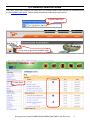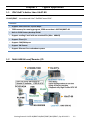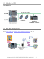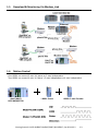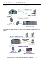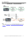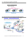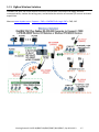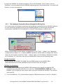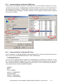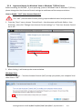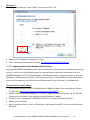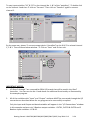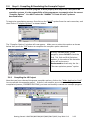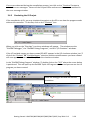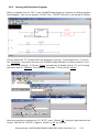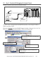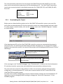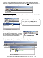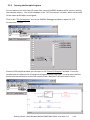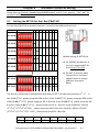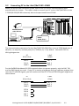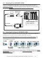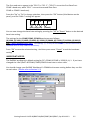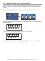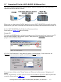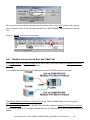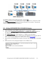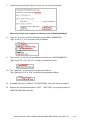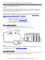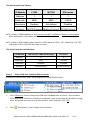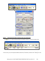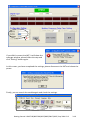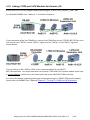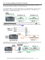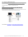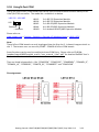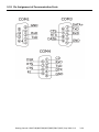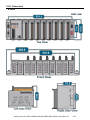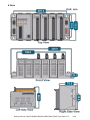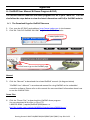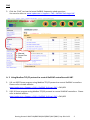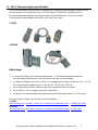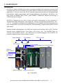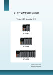
1
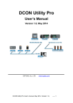
Getting Started: I-8437-80/8837-80/ 8437/8837/8417/8817 “I-8xx7” is the abbreviation of “I-8437-80/8837-80/8437/8837/8417/8817”, and the I-8x37 is the Ethernet PAC. ICP DAS CO., LTD. would like to congratulate you own your purchase of our ISaGRAF PACs I-8437-80/8837-80/8437/8837/8417/8817. The ease to integration of the controller system and the power of the IEC 61131-3 ISaGRAF software program combine to make a powerful, yet inexpensive industrial process control system. ISaGRAF PAC Series of ICP DAS includes : Please visit the website: www.icpdas.com > Product > Solutions > Soft PLC, ISaGRAF & Soft-GRAF HMI > ISaGRAF μPAC: iPAC: WinPAC: ViewPAC: XPAC: μPAC-7186EG/PEG, μPAC-5xx7 Series, I-7188EG, I-7188XG, iP-8xx7 Series, I-8xx7 Series, WP-8xx7 Series, WP-5xx7 Series VP-2xW7/4xx7 Series, VP-2117 XP-8xx7-CE6 Series, XP-8xx7-Atom-CE6 Series Legal Liability ICP DAS CO. , LTD. assumes no liability for any and all damages that may be incurred by the user as a consequence of this product. ICP DAS CO. , LTD. reserves the right to change this manual at any time without notice. ICP DAS CO. , LTD. constantly strives to provide our customers with the most reliable and accurate information possible regarding our products. However, ICP DAS CO. , LTD. assumes no responsibility for its use, or for any infringements of patents or other rights of third parties resulting from its use. Trademark & Copyright Notice The names of products are used for identification purposes only, and are the registered trademarks of their respective owners or companies. Technical Service Please contact local agent or email problem-report to [email protected]. New information can be found at www.icpdas.com. FAQ : www.icpdas.com > Support > FAQ > ISaGRAF Soft-Logic PAC Written by Chun Tsai, Spike Huang & Janice Hong, R&D dept. , ICP DAS Copyright © April 2002, by ICP DAS CO. , LTD. All Rights Reserved. Getting Started: I-8437-80/8837-80/8437/8837/8417/8817, Sep 2014 V3.2 1 Table of Contents Getting Started: I-8437-80/8837-80/ 8437/8837/8417/8817 ..................................... 1 Legal Liability ........................................................................................................................... 1 Trademark & Copyright Notice ............................................................................................... 1 Technical Service ..................................................................................................................... 1 Table of Contents....................................................................................................... 2 Reference Guide ........................................................................................................ 4 I/O Modules Selection Guide ..................................................................................... 5 Specifications: I-8437-80/8837-80/8437/8837/I-8417/8817....................................... 6 Chapter 1 Typical Application .............................................................................. 1-1 1.1 iPAC-8x47 is better than I-8x37-80 .............................................................................. 1-1 1.2 Multi-HMI & Local/Remote I/O ................................................................................... 1-1 1.3 Redundant Bus7000 ..................................................................................................... 1-2 1.4 SMS: Short Message Service ........................................................................................ 1-2 1.5 Download & Monitoring Via Modem_Link .................................................................. 1-3 1.6 Motion Control............................................................................................................. 1-3 1.7 Modbus Converter of I-7000 & I-87K I/O .................................................................... 1-4 1.8 Modbus Master ............................................................................................................ 1-5 1.9 Data Exchange through Ethernet & RS-485 ................................................................. 1-6 1.10 Active Control Data and I/O Acquisition Data Reporting System ................................ 1-6 1.11 ZigBee Wireless Solution.............................................................................................. 1-7 Chapter 2 Software Programming ....................................................................... 2-1 2.1 Step 1 - Installing the ISaGRAF Software ..................................................................... 2-1 2.1.1 The Hardware Protection Device (Dongle & USB Key-Pro) ..................................... 2-2 2.1.2 Important Notice for Window 2000 Users .............................................................. 2-3 2.1.3 Important Notice for Window NT Users .................................................................. 2-3 2.1.4 Important Notice for Windows Vista or Windows 7 (32-bit) Users......................... 2-4 2.1.5 Important Notice for Windows (64-bit) Users ......................................................... 2-5 2.1.6 Important Setting for Using Variable Arrays ............................................................ 2-6 2.2 Step 2 - Installing the ICP DAS Utilities for ISaGRAF .................................................... 2-7 2.3 Step 3 - Writing a Simple ISaGRAF Program ................................................................ 2-8 2.3.1 Open ISaGRAF-Project Management ....................................................................... 2-9 2.3.2 Creating An ISaGRAF User’s Group .......................................................................... 2-9 2.3.3 Creating a New ISaGRAF Project ............................................................................ 2-10 2.3.4 Declaring the ISaGRAF Project Variables ............................................................... 2-11 2.3.5 Create and Edit the ST - “ST1” Program ................................................................. 2-15 2.3.6 Create the LD - “LD1” Program............................................................................... 2-16 Getting Started: I-8437-80/8837-80/8437/8837/8417/8817, Sep 2014 V3.2 2 2.3.7 Edit the “LD1” Program .......................................................................................... 2-17 2.3.8 Connecting the I/O ................................................................................................. 2-23 2.4 Step 4 - Compiling & Simulating the Example Project ............................................... 2-25 2.4.1 Compiling the LD Project........................................................................................ 2-25 2.4.2 Simulating the LD Project ....................................................................................... 2-26 2.4.3 Running the Simulation Program ........................................................................... 2-27 2.5 Step 5 - Download & Debugging the Example Project .............................................. 2-29 2.5.1 Downloading the Project ....................................................................................... 2-30 2.5.2 Running the Example Program .............................................................................. 2-32 Chapter 3 Hardware System & Setting ................................................................. 3-1 3.1 Setting the NET-ID for the I-8xx7/8x37-80 .................................................................. 3-1 3.2 Connecting PC to the I-8xx7/8x37-80’s COM1 ............................................................ 3-2 3.3 Connecting PC to I-8417/8817’s COM2 ....................................................................... 3-3 3.4 Connecting PC to Several I-8417/8817’s COM2 .......................................................... 3-3 3.5 How to change Modbus RTU Baud Rate & Setup COM3 as Modbus Slave Port ......... 3-4 3.6 Deleting an ISaGRAF Project from the Controller........................................................ 3-6 3.7 Connecting PC to the I-8437-80/8837-80 Ethernet Port ............................................. 3-7 3.8 Modbus Connection to the I-8xx7/8x37-80 ................................................................. 3-8 3.9 Setting I-8437-80/8837-80’s IP & MASK & Gateway ................................................... 3-9 3.10 Setting COM1 as None-Modbus-Slave Port ............................................................... 3-11 3.11 Update I-8xx7/8x37-80’s Hardware Driver ................................................................ 3-12 3.12 Backup & Restore an ISaGRAF Project ....................................................................... 3-14 3.13 Pin assignment Of the Fbus ....................................................................................... 3-15 3.14 Setting I-7000 and I-87K Remote I/O by DCON Utility .............................................. 3-16 3.15 Linking I-7000 and I-87K Modules for Remote I/O .................................................... 3-20 3.16 Creating a Modbus Link with the Controller.............................................................. 3-21 3.17 Linking To an MMI Interface Device .......................................................................... 3-22 3.18 Using N-Port COM ...................................................................................................... 3-23 3.19 Pin Assignment of Communication Ports .................................................................. 3-24 3.20 Dimension .................................................................................................................. 3-25 Appendix ................................................................................................................... 1 A : ISaGRAF User Manual & Demo Program & FAQ .................................................................... 1 A. 1 The Download Page for ISaGRAF Resource ............................................................... 1 A. 2 Using Modbus TCP/IP protocol to control ISaGRAF controllers with VB? .................. 2 B : 10-ch Thermocouple Input Module ....................................................................................... 3 I-7018Z ..................................................................................................................................... 3 I-87018Z ................................................................................................................................... 3 C : RU-87P1/2/4/8 ....................................................................................................................... 4 Getting Started: I-8437-80/8837-80/8437/8837/8417/8817, Sep 2014 V3.2 3 Reference Guide ISaGRAF Resource on the Internet: Newly updated ISaGRAF IO libraries, drivers, demo, and manuals can be found at www.icpdas.com > Product > Solutions > Soft PLC, ISaGRAF & Soft-GRAF HMI > ISaGRAF ISaGRAF User’s Manual: CD-ROM: \napdos\isagraf\8000\english_manu\ user_manual_i_8xx7.pdf ISaGRAF (Chinese) User’s Manual: CD-ROM: \napdos\isagraf\8000\chinese_manu\chinese_user_manual_i_8xx7.pdf Web: ISaGRAF Web > Download – Manual Hardware Manual: Please refer to CD-ROM: \NAPDOS\8000\8000manual.pdf ftp://ftp. icpdas. com. tw/pub/cd/8000cd/napdos/8000/ Related Products: Industrial Ethernet Switch: NS-205/NS-208, RS-405/RS-408 www.icpdas.com > Product > Solutions > Industrial Ethernet Switch & Fber Switch > Unmanaged Ethernet Switches RS-232 to RS-422/485 Converter : I-7520R www.icpdas.com > Product> Solutions > Industrial Communication > Converter Power Supply : DP-665/660, KA-52F www.icpdas.com > Product > Solutions > Accessories > Power Supply High Profile I-8K/87K Series I/O Modules www.icpdas.com > Product > Solutions > Remote I/O Modules/Units > I-8K & I-87K FAQ: www.icpdas.com > Support > FAQ > ISaGRAF Soft-Logic PAC or ISaGRAF Web > Download – FAQ Getting Started: I-8437-80/8837-80/8437/8837/8417/8817, Sep 2014 V3.2 4 I/O Modules Selection Guide The I-8xx7 series PAC supports the I-8K/I-87K I/O modules and RS-485 remote I/O modules listed in the ISaGRAF Data Sheet. Please follow the below steps to get the new list. 1. www.icpdas.com 2. Click here to go to the ISaGRAF page 3. Data Sheet Getting Started: I-8437-80/8837-80/8437/8837/8417/8817, Sep 2014 V3.2 5 Specifications: I-8437-80/8837-80/8437/8837/I-8417/8817 Note: I-8x37 has phased out; please select compatible I-8x37-80. Models I-8417 I-8817 I-8437-80 I-8837-80 System Software OS MiniOS7 (DOS-like embedded operating system) Development Software ISaGRAF Ver. 3 IEC 61131-3 standard Languages LD, ST, FBD, SFC, IL & FC Max. Code Size 64 KB Scan Time Normal program: 5 ~ 100 ms Complex or Large program: 25 ~ 500 ms (or more) Normal program: 2 ~ 25 ms Complex or Large program: 10 ~ 125 ms (or more) CPU 80188, 40 MHz 80186, 80 MHz SRAM 512 KB Flash 512 KB EEPROM 2 KB NVRAM 31 bytes (battery backup, data valid up to 10 years) RTC (Real Time Clock) Provide second, minute, hour, date, day of week, month, year Watchdog Timer Yes (0.8 second) DIP Switch Yes (8 bits) ISaGRAF Software CPU Module Communication Ports Ethernet - RJ45 x 1, 10 Base-T COM1 RS-232 (TxD, RxD, GND) COM2 RS-485 (Data+, Data-) with internal self-tuner ASIC COM3 RS-232/RS-485 (RS-232: TxD, RxD, RTS, CTS, GND ; RS-485: Data+, Data-) COM4 RS-232: (Full modem signals) (TxD, RxD, RTS, CTS, DSR, DTR, CD, RI, GND) - SMMI LED Display Yes, 5-Digit Programmable LED Indicators 3 Push Buttons 4 I/O Expansion Slots 4 8 4 8 Slot Number Note: For I-8K and I-87K Modules Only Getting Started: I-8437-80/8837-80/8437/8837/8417/8817, Sep 2014 V3.2 6 Models I-8417 I-8817 I-8437-80 I-8837-80 Mechanical Dimensions (W x L x H) 230 mm x 110 mm x 75.5 mm: I-8417, I-8437-80 354 mm x 110 mm x 75.5 mm: I-8817, I-8837-80 Environmental Operating Temperature -25 ~ +75 °C Storage Temperature -30 ~ +85 °C Ambient Relative Humidity 5 ~ 95% RH (non-condensing) Power Input Range +10 ~ +30 VDC Protection Power reverse polarity protection Capacity 20 W Consumption 3.9 W 5.1 W 3.9 W 5.1 W Protocols (Note that certain protocols require optional devices) Modbus RTU/ASCII Master A max. of 2 ports: COM1 or COM3 or COM4 or COM5 (*). (To connect to other Modbus Slave devices.) A max. of 2 ports. (For connecting ISaGRAF, PC/HMI/OPC Server and HMI panels.) Modbus RTU Slave I-8x17: COM1/2 I-8x37-80: COM1/3 Modbus TCP/IP Slave - Max. 4 connections. (For connecting ISaGRAF & PC/HMI) User-defined Protocol Custom protocols can be applied at COM1, COM3, COM4 & COM5 ~ COM20 (*) by serial communication function blocks. Remote I/O One of COM3 or COM4 supports I-7000 I/O modules, I-87K base + I-87K Serial I/O boards, or RU-87Pn + I-87K High Profile I/O boards as remote I/O. A max. of 64 I-7000/87K remote I/O modules can connect to one PAC. Fbus Built-in COM3 Port to exchange data between ICP DAS's ISaGRAF PACs. Ebus (for I-8x37-80) - SMS: Short Message Service One of COM4 or COM5 (*) can link to a GSM Modem to support SMS. The user can request data/control the controller via a cellular phone. The controller can also send data and alarms to the user’s cellular phone. Optional GSM Modem: GTM-201-RS232 (850/900/1800/1900 GSM/GPRS External Modem) or other GSM/GPRS Modem. Modem Link Supports PC to remotely download & monitor the controller through a normal modem. MMICON/LCD One of COM3 or COM4 supports ICP DAS's MMICON. The is featured with a 240x 64 dot LCD and a 4 x 4 Keyboard. User can use it to display picture, string, integer, float, and input a character, string, integer and float. Redundant Bus7000 Two ISaGRAF PACs can link to remote I-7000 & I-87K I/O modules at the same time. Only one controller is active to control these Remote I/Os. If one is dead, the other one will take over the control of Remote I/O. (FAQ-084) Used to exchange data between ICP DAS ISaGRAF Ethernet PACs via the Ethernet port. Getting Started: I-8437-80/8837-80/8437/8837/8417/8817, Sep 2014 V3.2 7 Optional I/O Functions (Refer to the ISaGRAF PAC I/O Selection Guide for I/O Module list) PWM Output Pulse Width Modulation Output 8-ch max. for one controller. 500 HZ max. for Off = 1 & On = 1 ms Output square wave: Off: 1 ~ 32767 ms, On: 1 ~ 32767 ms Optional DO boards: I-8037, 8041, 8042, 8054, 8055, 8056, 8057,8060, 8063, 8064, 8065, 8066, 8068, 8069. (Relay Output boards cannot generate fast square wave ) Counters Parallel DI Counter 8-ch. max. for 1 controller. Counter value: 32-bit. 500 HZ max. Min. pulse width > 1 ms Optional DI boards: I-8040, 8042, 8051, 8052, 8053, 8054, 8055, 8058, 8063, 8077 Serial DI Counter Counter input: 100 Hz max. Counter value: 0 ~ 65535 (16-bit) Optional serial I-87k DI boards: I-87040, 87051, 87052, 87053, 87054, 87055, 87058, 87063 Remote DI Counter All remote I-7000 & I-87K DI modules support counters. 100Hz max. value: 0 ~ 65535 High Speed Counter I-87082: 100 kHz max. 32-bit, I-8080:450 kHz max. 32-bit Motion Motion Control Can integrate with one I-8091 (2-axis) or two I-8091 (4-axis) to do motion control. Ethernet communication is not available when doing motion control. SRAM Expansion Battery Backup SRAM With a S256/S512 (plug in the socket of the back-plane), data can also be stored in the S256/S512. PC can load these data via COM1 (or COM2 of I-8417/8817, or Ethernet Port of I-8437-80/8837-80). PC can also download pre-defined data to the S256/S512. Optional: S256: 256 KB, S512: 512 KB. *Note: The COM5 ~ COM20 ports are located in the expansion boards if they are installed in slots 0 ~ 7 of I-8xx7-80. * ISaGRAF FAQ: www.icpdas.com > Support > FAQ > ISaGRAF Soft-Logic PAC * ICP DAS recommends using NS-205/NS-208 or RS-405/408 (Ring Switch) Industrial Ethernet Switches. Getting Started: I-8437-80/8837-80/8437/8837/8417/8817, Sep 2014 V3.2 8 Chapter 1 1.1 Typical Application iPAC-8x47 is better than I-8x37-80 iP-8447/8847 - the advanced I-8xx7 ISaGRAF based iPAC. Features: • Support Dual Ethernet 10/100 Mbps • 768K memory for running program, 256K more than I-8437-80/8837-80 • Built-in 512K Battery backup SRAM • Support sending E-mail with an attached file (Max. 488 KB) • Support FRnet I/O • Support CAN/CANopen • Support VW Sensor • Support Ethernet Port redundant system 1.2 Multi-HMI & Local/Remote I/O Getting Started: I-8437-80/8837-80/8437/8837/8417/8817, Sep 2014 V3.2 1-1 1.3 Redundant Bus7000 I-8437-80/8837-80: 1.4 SMS: Short Message Service More at www.icpdas.com > Support > FAQ > ISaGRAF Soft-Logic PAC > FAQ-111 Getting Started: I-8437-80/8837-80/8437/8837/8417/8817, Sep 2014 V3.2 1-2 1.5 Download & Monitoring Via Modem_Link 1.6 Motion Control One I-8091 can control 2-axis: X-Y plane, or 2 axes independent Two I-8091 can control 4-axis: X-Y plane + 2 axes independent or 4 axes independent I-8417/8817/ 8437-80/8837-80 I-8091: 2 axes I-8090: 3 axes Encoder Getting Started: I-8437-80/8837-80/8437/8837/8417/8817, Sep 2014 V3.2 1-3 1.7 Modbus Converter of I-7000 & I-87K I/O I-8417/8817 can be a Modbus RTU serial converter of I-7000 & I-87K series I/O modules. I-8437-80/8837-80 can be a Modbus RTU serial & TCP/IP converter of I-7000 & I-87K series I/O modules. Getting Started: I-8437-80/8837-80/8437/8837/8417/8817, Sep 2014 V3.2 1-4 1.8 Modbus Master Up to 2 COM Ports (COM1, COM3, COM4 and COM5 in multi serial port board) can support Modbus RTU Master or ASCII Master Protocol to connect to other Modbus Slave devices. NOTE: COM5 ~ COM20 is optional from the I-8112/8114/8142/8144/8142i expansion board. Please visit to www.icpdas.com > Product > Solutions > Remote I/O Modules/Units > I-8K & I-87K Getting Started: I-8437-80/8837-80/8437/8837/8417/8817, Sep 2014 V3.2 1-5 1.9 Data Exchange through Ethernet & RS-485 Controller to Controller Data Exchange Ethernet : I-8437-80/8837-80 RS485 : I-8xx7/8x37-80 1.10 Active Control Data and I/O Acquisition Data Reporting System More at www.icpdas.com > Support > FAQ > ISaGRAF Soft-Logic PAC > FAQ-065 Getting Started: I-8437-80/8837-80/8437/8837/8417/8817, Sep 2014 V3.2 1-6 1.11 ZigBee Wireless Solution ISaGRAF PAC plus ZB-2550P and ZB-2551P RS-232/RS-485 Converters can apply wireless communication, reduce the wiring cost, and achieve the mission of remote I/O control and data acquisition. More at www.icpdas.com > Support > FAQ > ISaGRAF Soft-Logic PAC > FAQ-110 Getting Started: I-8437-80/8837-80/8437/8837/8417/8817, Sep 2014 V3.2 1-7 Chapter 2 Software Programming Please refer to CD-ROM: \napdos\isagraf\8000\english_manu\ “user_manual_i_8xx7. pdf” for detailed ISaGRAF User’s Manual. 2.1 Step 1 - Installing the ISaGRAF Software The user has to install two kinds of software before he can program on the ISaGRAF controller system. They are A. ISaGRAF Workbench B. ICP DAS Utilities for ISaGRAF User has to purchase at least one pcs. of ISaGRAF workbench Version 3 (ISaGRAF-256) to install on his PC to edit, download, monitor & debug the controller system. Item (B) is free and it is burned inside the CD-ROM which is delivered with the I-8xx7/8x37-80. Operating system Requirements: One of the following computer operating systems must be installed on the target computer system before you can install the ISaGRAF Workbench software program. Windows 95 / Windows 98 / Windows 2000 Windows NT Version 3.51 or Windows NT Version 4.0 Windows XP or Vista or Windows 7 (Please refer to www.icpdas.com > Support > FAQ > ISaGRAF Soft-Logic PAC > FAQ-117) Steps to Installing the ISaGRAF Workbench: If your operating system is Windows Vista or Windows 7 (32-bit), please refer to 2.1.4. If your operating system is Windows 7 (64-bit), please refer to 2.1.5. Insert the ISaGRAF Workbench CD into your CD-ROM drive. If your computer does not have the auto-start feature active, use the Windows Explorer and go to the CD-ROM drive where the Workbench CD is installed, then double-click on the “install.bat” file listed on the ISaGRAF CD. If the “install.bat” file is not found on your ISaGRAF CD, then double-click on the “ISaGRAF.exe” Select the language. file to start the installation process. Recommend to use "English" because this manual uses English version. Getting Started: I-8437-80/8837-80/8437/8837/8417/8817, Sep 2014 V3.2 2-1 To begin the ISaGRAF 3.x software program, click on the Windows “Start” button, then on “Programs”, and you should see the ISaGRAF program group as illustrated below. You could click “Projects” to start the program. 2.1.1 The Hardware Protection Device (Dongle & USB Key-Pro) You must install the hardware protection device (dongle) provided with the ISaGRAF software on your computers parallel port to for the ISaGRAF program to achieve fully authorized functionality. (ISaGRAF-32-E & ISaGRAF-32-C DO NOT need dongle or USB Key-Pro.) 1. 2. While using ISaGRAF and the dongle is plugged well, if the “Help” – “About” says “Maximum number of IO variables: 32”, it means ISaGRAF workbench cannot find the dongle well. Please reset your PC and then check the “Help” – “About” again. If it still displays “Maximum number of IO variables: 32”, the driver may not be installed well. Please do the following steps. Dongle Protection: Please execute the ISaGRAF CD_ROM \Sentinel5382\setup.exe for ISaGRAF-80 or \Sentinel\setup.exe for other ISaGRAF version and then reset the PC again. USB Key-Pro Protection: 1. To make your PC recognize the ISaGRAF USB protection-key, please un-plug the USB protection-key from your USB port first, then run “\Sentinel\SSD5411-32bit.exe” in the ISaGRAF 3.55 CD-ROM (or later version) after you have installed the ISaGRAF. Then please reset your PC. 2. To run ISaGRAF Ver. 3.5x, please always plug the USB protection-key in the PC’s USB port. Getting Started: I-8437-80/8837-80/8437/8837/8417/8817, Sep 2014 V3.2 2-2 2.1.2 Important Notice for Window 2000 Users If you close some ISaGRAF windows, it holds about 20 ~ 40 seconds (No response). This may caused by the procedure “CTFMON.EXE” of Windows 2000. First click on “Ctrl & Alt & Del” at the same time to stop the “CTFMON.EXE” process, and then you may create a short cut for the “ISaGRAF project manager”. And then check on “run in separate memory space” option in the shortcut property. 2. 2.1.3 1. Important Notice for Window NT Users If your computer is using the Windows NT operating system, you will need to add one line to the “isa.ini” file in the ISaGRAF Workbench “EXE” subdirectory. C:\ISAWIN\EXE\isa.ini You can use any ASCII based text editor (such as Notepad or UltraEdit32) to open the “isa.ini” file. Locate the [WS001] header in the “isa.ini” initialization file (it should be at the top of the file). Anywhere within the [WS001] header portion of the “isa.ini” initialization file, add the entry shown below within the [WS001] header: [WS001] NT=1 Isa=C: \ISAWIN IsaExe=C: \ISAWIN\EXE Group=Samples IsaApl=c: \isawin\smp IsaTmp=C: \ISAWIN\TMP Getting Started: I-8437-80/8837-80/8437/8837/8417/8817, Sep 2014 V3.2 2-3 2.1.4 Important Notice for Windows Vista or Windows 7 (32-bit) Users Before installing the ISaGRAF ; If your operating system is Windows Vista or Windows 7 (32-bit) , please change the User Account Control settings to avoid some of the setup restrictions. How to disable “UAC” (User Account Control) ? The “UAC” (User Account Control) setting requires administrator-level permission. 1. From the “Start” menu, choose “Control Panel > User Accounts and Family Safety > User Accounts”, then click “Change User Account Control settings” or “Turn User Account Control on or off”. 2. After clicking, it will show up the screen as below. Windows Vista: Uncheck the option – “Use User Account Control (UAC) to help you protect your computer”and then click on “OK”. Getting Started: I-8437-80/8837-80/8437/8837/8417/8817, Sep 2014 V3.2 2-4 Windows 7: Move the slider down to “Never Notify” and then click on “OK”. 3. Reboot your computer to apply the change. 4. After rebooting, please refer to section 2.1 Installing the ISaGRAF Software. 2.1.5 Important Notice for Windows (64-bit) Users Because the ISaGRAF Workbench can only be installed on a 32-bit version of Windows operating system, users can use the following ways to create a proper installation environment for the ISaGRAF Workbench 3.55. If using Windows XP Mode that can be installed on 64-bit version of Windows 7 Professional, Enterprise, and Ultimate editions. If using VMware Workstation/Player that can be installed on any 64-bit version of Windows OS (e.g., Windows 7 or Windows 8). Using Virtual PC and XP Mode: 1. Download Windows Virtual PC and Windows XP Mode installers from the Windows Virtual 2. 3. 4. 5. PC Web site (http://go.microsoft.com/fwlink/?LinkID=160479) Double-click on "WindowsXPMode_nn-NN.exe” (where nn-NN is the locale, e.g. en-US) and follow the instructions in the wizard to install Windows XP Mode. Double-click on "Windows6.1-KB958559-x64.msu” to install Windows Virtual PC. Reboot your computer. After rebooting, click on "Star > All Programs > Windows Virtual PC” and then click Windows XP Mode. Getting Started: I-8437-80/8837-80/8437/8837/8417/8817, Sep 2014 V3.2 2-5 6. Follow the instructions in the wizard to complete Windows XP Mode Setup and Configuration. Record the password that is provided during the Setup because it is required to log on to your virtual machine. 7. Now, go back to Section 2.1 to install the ISaGRAF. Using VMware Workstation/Player: 1. Download and install VMware Workstation 10 (trail version) on VMware website. https://my.vmware.com/web/vmware/info/slug/desktop_end_user_computing/vmware_workstation/10_0 2. Create a virtual machine running Windows XP (32-bit, SP3). 3. Install ISaGRAF Workbench 3.55 on a virtual machine. 4. Install ISaGRAF I/O Library on a virtual machine. 5. The related settings for a virtual machine. 6. Install USB dongle driver on a virtual machine. More at www.icpdas.com > Support > FAQ > ISaGRAF Soft-Logic PAC > FAQ-174 2.1.6 Important Setting for Using Variable Arrays Please add two more lines on the top of the c:\isawin\exe\isa.ini file to enable the usage of variable arrays. [DEBUG] Arrays=1 Getting Started: I-8437-80/8837-80/8437/8837/8417/8817, Sep 2014 V3.2 2-6 2.2 Step 2 - Installing the ICP DAS Utilities for ISaGRAF The “ICP DAS Utilities for ISaGRAF” consists of 3 major items. I/O libraries (For all ISaGRAF PAC) Modem_Link utility Auto-scan I/O utility Note: Make sure you have already installed the ISaGRAF Workbench program, IF NOT, please refer to Ch 2. 1 Step 1 before continuing. There is a CD-ROM supplied with each of the I-8xx7/8x37-80 controllers with the “ICP DAS Utilities for ISaGRAF”. Please insert the CD-ROM into your CD-ROM drive. Then run CD-ROM: \napdos\isagraf\setup. exe. Follow the steps to install it. Note: If “ICP DAS Utilities for ISaGRAF” is not in your CD-ROM, please refer to the website www.icpdas.com > Product > Solutions > Soft PLC, ISaGRAF & Soft-GRAF HMI > ISaGRAF > Driver to download “io_lib.zip” (please save the file in path C:\ to ensure the completed access). Getting Started: I-8437-80/8837-80/8437/8837/8417/8817, Sep 2014 V3.2 2-7 2.3 Step 3 - Writing a Simple ISaGRAF Program We are going to use ISaGRAF to write a simple ISaGRAF example program and then download it to the I-8xx7/8x37-80 controller to make it work. If you haven’t installed “ISaGRAF” & “ICP DAS Utilities for ISaGRAF”, please go back to 2. 1:Step 1 & 2. 2:Step 2. This example contains 2 programs. One is written in Structured Text (ST) and one in Ladder Logic (LD) language. Name of project group - “Test” Project name – “example1” One ST program – “ST1” One LD program – “LD1” Variables declaration: Name Type Attribute INIT Boolean Internal Initial value at “TRUE”. TRUE means 1st scan cycle OUT01 Boolean Output Output 1 OUT02 Boolean Output Output 2 OUT03 Boolean Output Output 3 K1 Boolean Input Push button 1 K2 Boolean Input Push button 2 T1 Timer Internal Description Time period of blinking ST program – “ST1” outline: IF INIT THEN (* Do init steps here *) INIT:= False; T1:= T#1500ms; END_IF; Getting Started: I-8437-80/8837-80/8437/8837/8417/8817, Sep 2014 V3.2 2-8 Ladder Logic Program Outline: 2.3.1 Open ISaGRAF-Project Management Click on the Windows [Start] [Programs] [ ISaGRAF 3. 4 ] [ Projects ] as shown below. 2.3.2 Creating An ISaGRAF User’s Group Click on the [Select Program Group] [New Group], then type in the name for the new user's group you wish to create, and last click on “OK”. 1. Getting Started: I-8437-80/8837-80/8437/8837/8417/8817, Sep 2014 V3.2 2-9 After click “OK”, the group name will show as below, please click “Select” to enter this group. 4. Click OK, the group name will show here 4 . 3 . 2.3.3 5 . 2 . Creating a New ISaGRAF Project To start a new ISaGRAF project, click on the “Create New Project” icon and then enter the name for the new project, you can then enter additional information for your project by clicking on the [Edit] > [Set Comment Text] as illustrated below. 1. 2 . 3 4 . Getting Started: I-8437-80/8837-80/8437/8837/8417/8817, Sep 2014 V3.2 2-10 You will now see the name of the new project in the “Project Management” window. Double click on the name of the new project to open the new project. Double click on the project name to get into the project window. 2.3.4 Declaring the ISaGRAF Project Variables Before you can start creating an ISaGRAF program, you must first declare the variables that will be used in the ISaGRAF program. Declaring Boolean: 1. To begin this process, first click on the “Dictionary” icon 2. Click on the “Boolean” tab to declare the Boolean variables that will be used in our example program. 3. Double click on the colored area below the “Boolean” tab, and a “Boolean Variable” window will open. 1 . 2 . 3 . (Please refer to ch2. 3 Variables declaration) 4. 5. 6. In this example, enter “INIT” as the variable name. Enter “Flag to indicate first scan cycle or not” as the comment. The type of “Attributes” in this example program – ”INIT” will be an “Internal”. Getting Started: I-8437-80/8837-80/8437/8837/8417/8817, Sep 2014 V3.2 2-11 7. 8. Checked the “set to true at init” item, we need to set the initial value of “INIT“ as “TRUE” when the project is running. Then press the “Store” button to save it. 4 . 5 . 6 . 8 . 7 . The new Boolean variable has now been declared. The other information areas that are provided for the programmer to fully explain how the variable will be handled. Note: You MUST make sure that the variable you have declared has the desired Attribute assigned. If you decide that you want to change a project variable’s attribute, just double click on the variable name and you can reassign the attribute for the variable Quick Declaration: There are three outputs used in this example program named “OUT01, OUT02, and OUT03”. ISaGRAF provides a quick and easy way to declare like variables that are sequentially ordered. To begin this process, 1. 2. 3. 4. Click on the “Quick Declaration” icon. Enter in the output number that you will start within the “Numbering” from and “To” field (this example uses from 1 to 3). Enter the “Symbol” name for the output variables being declared. Lastly, set the attribute to “Output and then press “OK”. Getting Started: I-8437-80/8837-80/8437/8837/8417/8817, Sep 2014 V3.2 2-12 1. 5. 2. 3. 4. All three outputs will be immediately added to the “Global Boolean” window. Please click “Save” button to save them. Use the same method as former to create another 2 variables – “K1” & “K2” however with “input” attribution. Getting Started: I-8437-80/8837-80/8437/8837/8417/8817, Sep 2014 V3.2 2-13 Declaring Timer To declare the timer (T1) variable used in this example program, click on the “Timers” tab in the setup screen and double click on the colored area. 1 . 2 . Enter the Name as “T1”, set the “Attributes” to “Internal”, the “Initial Value” to “T#1s”, and then click on the “Store” button. 3 . 4 . 5 . 6 . Then please click on “X” to close the “dictionary” window. 7 Getting Started: I-8437-80/8837-80/8437/8837/8417/8817, Sep 2014 V3.2 2-14 2.3.5 Create and Edit the ST - “ST1” Program In this project we need an ST program to handle the “INIT” variable. 1. Click on “Create new program” in the window. 2. Given the Name as “ST1”, Comment as “Handle INIT variable”, Language as “ST: Structured Text”, & Style as “Begin: Main program”. Then click on “OK”. 1. 2. Now we have one program inside this project. ISaGRAF will run every program one time in each PLC scan cycle. Programs in the “begin” area will run first, then the “Sequential” area, and last the “End” area. An ISaGRAF cycle run in the way as the below scheme. Scan all inputs Process ‘begin’ area ISaGRAF Cycle Process ‘Sequential’ area Process ‘End’ area Refresh all outputs Getting Started: I-8437-80/8837-80/8437/8837/8417/8817, Sep 2014 V3.2 2-15 Double click on “ST1” program to edit it. Click on “save” and then exit when you finish it. Note: Any character inside between (* and *) is the comment. 1 . 2 . IF INIT THEN (* Do init steps here *) INIT := False; T1 := T#1500ms; END_IF; Codes written here run only one time in the first scan cycle. They are usually some initial setting codes. 程式段只在第 1 個 Scan 週期時執行一遍. 2.3.6 Create the LD - “LD1” Program 之後的 Scan 週期都不會執行到此程式段. Click on the “Create New Program” icon and the “New Program” window will appear. Enter the “Name” as “LD1”. Next, click on the “Language” scroll button and select “Quick LD: Ladder Diagram” and make sure the “Style” is set to “End: Main Program”. You can add any desired text to the “Comment” section for the LD program, but it isn’t required. Now we have two programs inside this project. Please double click on the “LD1” to get into it. Getting Started: I-8437-80/8837-80/8437/8837/8417/8817, Sep 2014 V3.2 2-16 2.3.7 Edit the “LD1” Program When you double click on the “LD1” name the “Quick LD Program” window will appear. To start programming our LD program, click on “Edit” from the main menu bar, and then click on “Insert Rung”. “Insert Rung” means to insert a basic LD rung just above the current position. Or, you may just simply click on the “F2 (Contact on the Left)” icon, and the following will appear within the Quick LD Program window. We are going to write the first line of the LD1 program. Move the cursor to the first “contact” and then click on “cut” to delete it. Move the cursor to the first contact and then click on “cut” to delete it Getting Started: I-8437-80/8837-80/8437/8837/8417/8817, Sep 2014 V3.2 2-17 Click on the “F6 (Block on the left)” icon and you will create a block on the left of the “coil”. Now we are going to assign the associated variable & constant to each item. Double click anywhere inside the block and the “Function Block” assignment window appears. Double click on anywhere inside the block Select the “BLINK” type function block and press “OK”. To learn how the “BLINK” function operates you can click on the “Info” button for a detailed explanation of its functionality. 2. Click on “Info” to get detailed explanation. 1. Getting Started: I-8437-80/8837-80/8437/8837/8417/8817, Sep 2014 V3.2 2-18 Now move your cursor to the left of the parameter “CYCLE” of the “BLINK” block. Double click on it, select “Timer” and then double click on variable name - “T1” 1 . 2. 3. Move your cursor to the “coil”. Double click on it, select “Boolean” and then double click on variable name – “OUT01”. 1. Getting Started: I-8437-80/8837-80/8437/8837/8417/8817, Sep 2014 V3.2 2-19 2. 3. Click on “coil” icon to create one another coil below the “OUT01”, and then assign a Boolean name – “OUT02” to it. 1. Then we have the below window. To insert the second LD rung, move the cursor to be under the first rung, then click on “Edit” – “Insert rung”. Getting Started: I-8437-80/8837-80/8437/8837/8417/8817, Sep 2014 V3.2 2-20 1. 2. Using the same way as former to assign name “K1” and “OUT03” to the correct position. To assign proper type to the “contact” & “coil”, move the cursor to “K1” and then slowly click on “Coil/contact type” icon several times to get the correct type. In this example, K1 has type of “P” while OUT03 has type of “S”. Getting Started: I-8437-80/8837-80/8437/8837/8417/8817, Sep 2014 V3.2 2-21 2. 1. By the same way to create the third rung as below. Note that K2 has type of “P”; OUT03 has type of “R”. The LD1 program is finished now, click on the “Save” icon and then exit. 2. 1. Getting Started: I-8437-80/8837-80/8437/8837/8417/8817, Sep 2014 V3.2 2-22 2.3.8 Connecting the I/O We have defined variables name of “OUT01”, “OUT02” & “OUT03” as “output” attribution, while “K1” & “K2” as “input” attribution in step 2. 3. 4. These “input” & “output” variable should be map to physical I/O in the controller before they can work. To do that, click on “I/O connection” to get into the I/O connection window. Double click on the No. 8 slot & then check on the “Boards” & double click on the “push4key: 4 button on panel of 8xx7”. 1. Click on “Note” to get explanation of this I/O device. 3. 2. Then we have this window. Getting Started: I-8437-80/8837-80/8437/8837/8417/8817, Sep 2014 V3.2 2-23 To map input variables “K1” & “K2” to the channel No. 1 & 2 of the “push4key”, double click on the channel 1 and then click on “Connect”. Then click on “Connect” again to connect channel 2. 1. 2. By the same way, please connect output device “show3led” to slot 9 & its related channel 1, 2 & 3. Then we have below window. Click on “Save” and then exit. 4. 3. 2. 1. IMPORTANT NOTICE: 1. I/O Slots 0 through 7 are reserved for REAL I/O boards that will be used in the I-8xx7 controller. You can use slot No. 8 and above for additional functionality as illustrated by the example program. 2. All of the variables with “Input” and “Output” attribute MUST be connected through the I/O connection as described above for any program to be successfully compiled. Only the Input and Output attributed variables will appear in the “I/O Connections” window. In this example we have only 3 Boolean output variables - OUT01, OUT02 & OUT03 and 2 Boolean input variables – K1 & K2. Getting Started: I-8437-80/8837-80/8437/8837/8417/8817, Sep 2014 V3.2 2-24 2.4 Step 4 - Compiling & Simulating the Example Project ★ For ANY AND EVERY ISaGRAF program to work properly with any of the I-8xx7/8x37-80 controller systems, it is the responsibility of the programmer to properly select the correct “Compiler Options”. You MUST select the “ISA86M: TIC Code for Intel” option as described below. To begin the compilation process, first click on the “MAKE” option from the main menu bar, and then click on “Compiler Options” as shown below. The “Compiler Options” window will now appear. Make sure to select the options as shown below then press the “OK” button to complete the compiler option selections. If using “Variable Array” in the program, please DO NOT check the 2nd , 7th , 8th and 9 th Optimizer options, or the value of the Variable array will be incorrect. Recommend to check only the 1st – “Run two optimizer passes” option. 2.4.1 Compiling the LD Project Now that you have selected the proper compiler options, click on the “Make Application Code” icon to compile the example project. If there is no compiler errors detected during the compilation process, CONGRATULATIONS, you have successfully created our example program. Getting Started: I-8437-80/8837-80/8437/8837/8417/8817, Sep 2014 V3.2 2-25 If errors are detected during the compilation process, just click on the “Continue” button to review the error messages. Return to the Project Editor and correct the errors as outlined in the error message window. 2.4.2 Simulating the LD Project If the compilation is Ok, you may simulate the project on the PC to see how the program works without the controller. To do that, click on the “Simulate” icon. When you click on the “Simulate” icon three windows will appear. The windows are the “ISaGRAF Debugger”, the “ISaGRAF Debug Programs”, and the “I/O Simulator” windows. If the I/O variable names you have created DO NOT appears in the I/O simulator window, just click on the “Options” “Variable Names” selection and the variable names you have created will now appear next to each of the I/O’s in the simulator window. In the “ISaGRAF Debug Program” window, double click on the “LD1” where the cursor below is positioned. This will open up the ISaGRAF Quick LD Program window and you can see the LD program you have created. Close the debugger window will exit the simulation. 1. 2. Getting Started: I-8437-80/8837-80/8437/8837/8417/8817, Sep 2014 V3.2 2-26 2.4.3 Running the Simulation Program When you double click on “LD1” in the “ISaGRAF Debug Programs” window, the follow window should appear. You can see outputs “OUT01” thru. “OUT03” will blink in the period of 1500ms. You can adjust the “T1” variable while the program is running. To accomplish this, click on the “Dictionary” icon which will open the “ISaGRAF Global Variables” window as shown in the first two pictures below. Click on “Timer” tab and then double click on “T1” to change the timer value to “T#500ms” (this means 0. 5 second). Then click on “Write”. 1. 2. 3. 4. 5. Now we are going to simulate the “K1” & “K2” input. Click on “K1” using the right button of the mouse. You will see “OUT03” is lighted. Please try “K2” by yourself. Getting Started: I-8437-80/8837-80/8437/8837/8417/8817, Sep 2014 V3.2 2-27 Click on “K1” using the right button of the mouse To exit simulation, please close the debugger window. Close debugger will end simulation. Getting Started: I-8437-80/8837-80/8437/8837/8417/8817, Sep 2014 V3.2 2-28 2.5 Step 5 - Download & Debugging the Example Project To begin this process, please install the hardware as below. i-8XX7 POWER SUPPLY +10V~30VDC RS-232 Cable COM1 19200, 8 N, 1 HOST COMPUTER The RS-232 cable is coming with the I-8xx7/8x37-80 controller; it is for linking PC’s COM1 or COM2 to controller’s COM1. Click on the “Link Setup” icon in the “ISaGRAF Programs” window. When you click on the “Link Setup” icon, the following window will appear. Please set the proper value. 1. 2. NET-ID of the I-8x17/8x37-80. Please refer to Section 3.1. 3. Comm.’s port of your PC 5. 4. Click it to set Comm.’s other parameter Comm.’s parameter, default is 19200, N, 8, 1, No flow control Getting Started: I-8437-80/8837-80/8437/8837/8417/8817, Sep 2014 V3.2 2-29 The communication parameters for the target I-8xx7/8x37-80 controller MUST be set to the same serial communication parameters for the development PC. For I-8x17/8x37 controllers (serial port communications), the default parameters for COM1 (RS-232) and COM2 (RS-485) Ports are: Baud rate: Parity: Format: Flow control: 2.5.1 19200 none 8 bits, 1 stop none Downloading the Project Before you can download the project to the I-8xx7/8x37-80 controller system, you must first verify that your development PC and the controller system are communicating with each other. To verify proper communication, click on the “Debug” icon in the “ISaGRAF Programs” window as shown below. If the development PC and the I-8xx7/8x37-80 controller system are communicating properly with each other, the following window displayed below will appear (or if a program is already loaded in the controller system, the name of the project will be displayed with the word “Active” following it. Your project name in the ISaGRAF software on the PC. Current running project name inside the controller. If the message in the “ISaGRAF Debugger” says “Disconnected”, it means that the development PC and the controller system have not established communications with each other. The most common causes for this problem is either the serial port cable not being properly configured, or the development PC’s serial port communications DO NOT match that of the I-8xx7/8x37-80 controller system. You may have to either change the serial port communication settings for the development PC (which may require changing a BIOS setting) or change the “Serial Link Parameters” in the ISaGRAF program. Getting Started: I-8437-80/8837-80/8437/8837/8417/8817, Sep 2014 V3.2 2-30 If there is a project already loaded in the controller system you will need to stop that project before you can download the example project. Click on the “STOP” icon as illustrated above to halt any applications that may be running. Starting the Downloading Process From the “ISaGRAF Debugger” window click on the “Download” icon, then click on “ISA86M: TIC Code for Intel” from the “Download” window as shown below. If “ISA86M: TIC code for Intel” is not found here, Please refer to ch 2.4 : Step 4 to check the option & compile the project again. The example project will now start downloading to the I-8xx7/8x37-80 controller system. A progress bar will appear in the “ISaGRAF Debugger” window showing the project downloading progress. When the example project has successfully completed the downloading process to the I-8xx7/8x37-80 controller system the following two windows will appear. Getting Started: I-8437-80/8837-80/8437/8837/8417/8817, Sep 2014 V3.2 2-31 2.5.2 Running the Example Program You can observe the real time I/O status from several ISaGRAF windows while you are running the example project. One of the windows is the “I/O Connections” window, which shows each of the inputs and outputs as assigned. Click on the “I/O Connections” icon in the ISaGRAF Debugger window to open the “I/O Connections” screen. Another VERY helpful window you can open is the “Quick LD Program” window. From this window you can observe the LD program being executed in real time. You may push the first button and second button on the front panel of the I-8xx7/8x37-80 controller to test it. Getting Started: I-8437-80/8837-80/8437/8837/8417/8817, Sep 2014 V3.2 2-32 Though there are numerous steps involved in creating and downloading an ISaGRAF program, each step is quick and easy to accomplish, and the end result is a powerful and flexible control development environment for the I-8xx7/8x37-80 controller systems. PRACTICE, PRACTICE, PRACTICE! Now that you have successfully created and ran your first ISaGRAF program with the I-8xx7/8x37-80 controller system, you should practice creating more elaborate and powerful programs. Like any other computer development environment, practice and experimentation is the key to understanding and success, GOOD LUCK! Getting Started: I-8437-80/8837-80/8437/8837/8417/8817, Sep 2014 V3.2 2-33 Chapter 3 Hardware System & Setting Please refer to CD-ROM: \napdos\isagraf\8000\english_manu\ “user_manual_i_8xx7. pdf” for detailed ISaGRAF User’s Manual. 3.1 Setting the NET-ID for the I-8xx7/8x37-80 For the I-8xx7/8x37-80 to properly operate, it must first be addressed correctly. Hex. DIP Switch 1 2 3 4 5 6 7 8 NET-ID=00 NET-ID=01 ON NET-ID=02 ON NET-ID=03 ON ON NET-ID=04 Default setting NET-ID=01 ★ For ISaGRAF workbench , it can only recognize NET-ID from 01 to FF (1~255). ON NET-ID=FE ON ON ON ON ON ON ON NET-ID=FF ON ON ON ON ON ON ON ON ★ The NET-ID of every Main Control Unit in the same network must be unique (different from each other). The Net-ID is expressed as Hexadecimal (Hex) and the DIP 1 to 8 were expressed as 20 ~ 27,If Net-ID=01 (20=1),please setup the DIP1 to ON. If Net-ID=02 (21=2),please setup the DIP2 to ON. If Net-ID=03 (20+21=3),please setup the DIP 1、2 to ON. If Net-ID=04 (22=4),please setup the DIP 3 to ON. If Net-ID=05 (20+22=5),please setup the DIP 1、3 to ON. If Net-ID=FE(16)= 254(10) (21+22+23+24+25+26+27=254),please setup the DIP 2 ~ 8 to ON. If Net-ID= FF(16)= 255(10) (20+21+22+23+24+25+26+27=255),please setup the DIP 1 ~ 8 to ON. DIP 1 0 2 =1 2 3 4 1 2 3 2 =2 2 =4 2 =8 5 4 2 =16 6 5 2 =32 7 6 2 =64 8 7 2 =128 Getting Started: I-8437-80/8837-80/8437/8837/8417/8817, Sep 2014 V3.2 3-1 3.2 Connecting PC to the I-8xx7/8x37-80’s COM1 When you receive your controller system, there is one (1) RS-232 communications cable provided with the system. The cable is used to connect your PC to the I-8xx7/8x37-80 or to an I-7520R (RS-232/RS-485 converter) that can be purchased from ICP DAS. i-8XX7 POWER SUPPLY +10 V~30 VDC RS-232 Cable COM1 19200, 8 N, 1 HOST COMPUTER The communication parameters for the I-8xx7/8x37-80 COM1 Port is set to 19200 baud rate, 8 data bits, no stop bits, and one parity bit (“19200, 8, N, 1”) by default. Normal RS-232 Pin Wiring Assignments PC 9-Pin D-Sub RxD 2 TxD 3 GND 5 I-8xx7 COM1 TxD 2 RxD 3 GND 5 For the ISaGRAF Workbench RS-232 communications to operate properly, only the RxD, TxD, and the GND signals are used. If your PC is running a hardware device or software program that uses the CTS and DSR signals, you will need to wire the RTS-CTS and DTR-DSR signals together as shown below. PC 9-Pin D-Sub RxD 2 TxD 3 GND 5 I-8xx7 COM1 TxD 2 RxD 3 GND 5 DTR 4 DSR 6 RTS 7 CTS 8 Getting Started: I-8437-80/8837-80/8437/8837/8417/8817, Sep 2014 V3.2 3-2 3.3 Connecting PC to I-8417/8817’s COM2 If your PC is connecting to an I-8417/8817's COM2 Port (RS-485), the maximum distance between the I-7520R (the RS-232/RS-485 converter) and the I-8417/8817 controller is up to 1,200 meters (4,000 feet). The distance between these two is dependent on the baud rate; the rule to follow is the lower you set the baud rate, the longer the distance can be. POWER SUPPLY +10V~+30VDC i-8X17 V+ GND HOST COMPUTER RS-232 Cable GND COM2 of I-8417/8817 Default 19200, 8, N, 1 V+ DATADATA+ I-7520R 3.4 Connecting PC to Several I-8417/8817’s COM2 An additional feature of using the COM2 Port of the I-8417/8817 is that you can configure an RS-485 network from one PC to link to numerous I-8417/8817 controllers. The PC can download ISaGRAF applications to each controller on the RS-485 network. The maximum number of controllers that can be networked via the RS-485 network is 255 (Not recommended to use so many). To create an RS-485 network you must first insure that each I-8417/8817 controller has a unique NET-ID address, and each of the controllers link the “DATA+” to the “DATA+” signal and the “DATA-” to the “DATA-” signal. Getting Started: I-8437-80/8837-80/8437/8837/8417/8817, Sep 2014 V3.2 3-3 Lastly, you must plug ONE of the I-8417/8817's JP-1 and JP-2 on the power board to position 1 to 2, (resistance applied to the network). The other I-8417/8817's JP-1 and JP-2 plugs should be left at the default setting of connecting 2 to 3 (no resistance). It is recommended to add two terminal resistors (try 220, then 110, and then 330 if the RS-485 communication is not stable) on the nearest I-8x17 and farthest I-8x17 for long distance RS-485 connection. 3.5 How to change Modbus RTU Baud Rate & Setup COM3 as Modbus Slave Port The ports which support Modbus Slave & their default setting: I-8417/8817: COM1 (RS-232 is 19200) and COM2 (RS-485 is 19200) I-8x37/8x77: COM1 (RS-232 is 19200) and COM3 (RS-485/RS-232 is “-” , Default: None- Modbus Slave) The baud rate can be set between 300、600、1200、2400、4800、9600、19200、38400、57600、 115200 bps (bit per second). To change the baud rate setting on the COM1 & I-8417/8817’s COM2 Port, first power off the controller. Then press in and hold in the first two buttons on the front panel of the controller and then power back up the controller system as shown below. Getting Started: I-8437-80/8837-80/8437/8837/8417/8817, Sep 2014 V3.2 3-4 The first read out to appear is the “SEL 0” or “SEL 1”. (“SEL 0” is to set the first Slave Port: COM1’s baud rate, while “SEL 1” is to set the second Slave Port: COM2 or COM3’s baud rate). Press the “Up” or “Dn” to change selection, then press the “OK” button (third button on the panel), and the “BAU x” setting will appear. B A U (Dn) (Up) (Ok) 4 (Cancel) You can now change the baud rate setting by pressing the “UP” or “Down” button to the desired baud rate setting. The settings for the COM1/COM2 /COM3 baud rate are as follows: (0) 1200, (1) 2400, (2) 4800, (3) 9600, (4) 19200, (5) 38400, (6) 57600, (7) 115200, (8) 300 (9) 600 (-) None-Modbus Slave Port. The setting “(-)” is only for the COM3! ( You can select one of the baud rates to setup COM3 as Slave Port). Press “OK” to save the selected setting. And then press some “Cancel” to exit the hardware setting. IMPORTANT NOTICE: The ISaGRAF workbench’s default setting for PC’s COM1 & COM2 is 19200, 8, N, 1. If you have changed the I-8xx7/8x37-80 COM1/COM2/COM3’s baud rate to other value. You should change your ISaGRAF Workbench’s COMM to the same setting before they can link to each other. (Please refer to Section 2. 5) Getting Started: I-8437-80/8837-80/8437/8837/8417/8817, Sep 2014 V3.2 3-5 3.6 Deleting an ISaGRAF Project from the Controller There may be occasions when you will need to delete the ISaGRAF project from the controller system. To begin this, you follow the same control start up routine as changing the baud rate. You first press and hold the first two buttons on the front panel of the controller and then power back up the I-8xx7/8x37-80 controller to gain the ability to change the parameters. When the first display appears, press the “Up” or “Down” button until “SEL 2” (Select 2) appears in the LED readout. S E L 2 (Up) (Dn) (Ok) (Cancel) Press the “Up” or “Down” buttons until “dEL” appears in the LED readout. d E L y (Up) (Dn) (Ok) (Cancel) Press the “Up” or “Down” buttons until “y” appears in the LED readout then press the “OK” button. This will delete the currently installed ISaGRAF project from the controller system. After that press some “Cancel” to exit the hardware setting. Getting Started: I-8437-80/8837-80/8437/8837/8417/8817, Sep 2014 V3.2 3-6 3.7 Connecting PC to the I-8437-80/8837-80 Ethernet Port The I-8437-80/8837-80 controller systems feature a built in Ethernet Port. The COM2 Port is replaced from an RS-485 to Ethernet. Before you can download an ISaGRAF application to the I-8437-80/8837-80 controller using the Ethernet Port, you must first setup the Ethernet Port to properly communicate with the host PC. On the I-8437-80/8837-80, Set IP, Mask and Gateway address: Please refer to section 3. 9 to do this setting. On your PC: First open an ISaGRAF project and select a program you wish to communicate between your PC and the I-8437-80/8837-80 controller system. Next, select the “Link Setup” button on the project screen as shown below. A “PC-PLC Link Parameters” dialog box will appear as shown below. From here select the “Ethernet” communications option and click on the “Setup” button. 1. 2. Once you have clicked on the “Setup” button, an “Ethernet Link Parameters” dialog box will appear. Set the “Port Number” to “502” and enter in the Internet address (IP) of the I-8437-80/8837-80 controller, Please refer to section 3. 9 Getting Started: I-8437-80/8837-80/8437/8837/8417/8817, Sep 2014 V3.2 3-7 Once you have entered the appropriate information, click on the “OK” button, and now you have configured your PC to communicate with the I-8437-80/8837-80 through the Ethernet Port. Click on “Debug” to link to the controller. 3.8 Modbus Connection to the I-8xx7/8x37-80 The COM1: RS-232 & COM2: RS-485 of the I-8417/8817 controller supports Modbus RTU Slave protocol by default. They can be linked by (1) ISaGRAF Workbench or by (2) HMI devices or by (3) SCADA software as below. The COM1: RS-232 & COM3: RS-232/RS-485 of the I-8437-80/8837-80 controller supports Modbus RTU Slave protocol by default. The Ethernet Port of the I-8437-80/8837-80 controller supports Modbus TCP/IP Slave protocol. They can be linked by (1) ISaGRAF Workbench or by (2) HMI devices or by (3) SCADA software as below. Getting Started: I-8437-80/8837-80/8437/8837/8417/8817, Sep 2014 V3.2 3-8 The Modbus TCP/IP protocol’s Ethernet Port No. is fixed as 502. Up to 4 PCs can link to one I-8437-80/8837-80 throughout Ethernet Port. Another PC or HMI can link to COM1: RS-232 Port (Modbus RTU Slave protocol) of the controller. Therefore the maximum number of clients can be linked is 5. 3.9 1. 2. 3. 4. 5. 6. Setting I-8437-80/8837-80’s IP & MASK & Gateway Create a file folder named “8000” in your hard drive. For example, “c:\8000”. Copy CD-ROM: \Napdos\ISaGRAF\8000\Driver\. . . . \7188xw. exe, 7188xw. ini from the CD_ROM into your “8000” folder. Run “\8000\7188xw. exe” in your hard drive. A “7188xw” screen will appear. Link from COM1 or COM2 of PC to COM1 of the I-8437-80/8837-80 controller by a RS-232 cable. (If you use other COM Port (ex. COM5), please refer to ch3. 11 step4) Power off the I-8437-80/8837-80 controller, connect pin “INIT” to “INIT COM”, then power it up. If the connection is Ok, messages will appear on the 7188xw screen. Getting Started: I-8437-80/8837-80/8437/8837/8417/8817, Sep 2014 V3.2 3-9 7. Use DOS command (ipconfig) to search out the setup of network. Please according as your computer to following setup (IP/MASK/GATEWAY) 8. Type “ip” to see the current IP address of the I-8437-80/8837-80. Type “ip 10. 0. 0. xxx” to setup a new IP address 9. Type “mask” to see the current address mask of the I-8437-80/8837-80. Type “mask 255. 255. 255. 0” to setup a new address mask. 10. Type “gateway” to see the current gateway address. Type “gateway 10. 0. 0. 254” to setup a new gateway address. 11. Press ALT_X to exit “7188xw”, or COM1/COM2 of the PC will be occupied. 12. Remove the connection between “INIT” - “INIT COM”; recycle the power of I-8437-80/8837-80 controller. Getting Started: I-8437-80/8837-80/8437/8837/8417/8817, Sep 2014 V3.2 3-10 3.10 Setting COM1 as None-Modbus-Slave Port COM1 of the I-8xx7/8x37-80 supports Modbus RTU Slave protocol by default. User may change it to a None-Modbus-Slave Port for other usage. For example, user may write his own defined protocol on COM1 or use COM1 as a Modbus Master Port. 1. 2. 3. 4. 5. 6. 7. 8. Create a file folder named “8000” in your hard drive. For example,”c:\8000”. Copy CD-ROM: \Napdos\ISaGRAF\8000\Driver\. . . \7188xw. exe, 7188xw. ini from the CD_ROM into your “8000” folder. Run “\8000\7188xw. exe” in your hard drive. A “7188xw” screen will appear. Link from COM1 or COM2 of PC to COM1 of the I-8xx7 by a RS-232 cable. If you use other COM Port (ex. COM5), please refer to ch3. 11 step4. Power off the I-8xx7/8x37-80, connect pin “INIT” to “INIT COM”, then power it up. If the connection is Ok, “I-8000>“ messages will appear on the 7188xw screen. Type “isa *f=1” to free COM1 (set COM1 as none-Modbus-Slave Port) 9. Press ALT+X to exit “7188xw”, or COM1/COM2 of the PC will be occupied. 10. Remove the connection between “INIT” - “INIT COM”; recycle the power of the controller. IMPORTANT NOTICE: If user wants COM1 to be back to a Modbus RTU Slave Port again, follow the same step 1 to 6 & then type “isa *f=0”. If the command doesn’t support, please refer to the next section to update the hardware driver. Getting Started: I-8437-80/8837-80/8437/8837/8417/8817, Sep 2014 V3.2 3-11 3.11 Update I-8xx7/8x37-80’s Hardware Driver Our newly released driver can also be obtained from the below website: www.icpdas.com > Product > Solutions > Soft PLC, ISaGRAF & Soft-GRAF HMI > ISaGRAF > Driver (Please extract the zip file) To Know The Current Driver Version (We use driver 3. 16 as an example) 1. 2. Create a file folder named “8000” in your hard drive. For example, “c:\8000”. Copy Napdos\ISaGRAF\8000\Driver\40m\3. 16\Napdos\ISaGRAF\8000\Driver\40m\3. 16\ 7188xw. exe, 7188xw. f4, 7188xw. ini, 8k050408. img, autoexec. bat, isa. exe, isa_data. exe from the CD_ROM into your “8000” folder. 3. Run “\8000\7188xw. exe” in your hard drive. A “7188xw” screen will appear (Press F1 for help). Link COM1 or COM2 of your PC to COM1 of the controller through a RS-232 cable. If you use other COM Port (ex. COM5), please modify the first line of “7188xw. ini”. 4. 5. 6. Power off I-8X417/8X37, connect pin “INIT” to “INIT COM” and then power it up. If the connection is Ok, “I-8000>“ messages will appear on the 7188xw screen. 7. 8. Type “ver” to see the current OS version & date. Type “isa *p=“ to see the current driver version No. & setting of the controller. To Upgrade an ISaGRAF Embedded Driver 1. 2. Power off the controller, connect pin “INIT” to “INIT COM” and then power it up. Press “F4” to auto download the following files and reboot system. (isa_data. exe, autoexec. bat, isa. exe, 8k050408. img) Getting Started: I-8437-80/8837-80/8437/8837/8417/8817, Sep 2014 V3.2 3-12 Wait about 60 sec. to update ISaGRAF system & DO NOT REMOVE THE POWER 3. Type “dir” to make sure “autoexec. bat” and “isa. exe” are well burned 4. 5. Press ALT+X to exit “7188xw”. Remove the connection between “INIT” - “INIT COM”; recycle the power of the controller. Getting Started: I-8437-80/8837-80/8437/8837/8417/8817, Sep 2014 V3.2 3-13 3.12 Backup & Restore an ISaGRAF Project For archiving purposes you can “Back Up” and “Restore” an ISaGRAF project. For example, you may want someone to test your program or email to service@icpdas. com for ICP DAS’s ISaGRAF service. Backing Up an ISaGRAF Project Open the “ISaGRAF Project Management” window, select “Tools” from the menu bar, click on “Archive”, and then click on “Projects”. An “Archive Projects” window will open which allows you to designate where you want to save the ISaGRAF project to. Click on the name of the ISaGRAF project you want to backup, and then click on the “Backup” button. You can compress the size of the file you have backed up by clicking on the “Compress” checkbox BEFORE you click on the “Backup” button. 1. 3. 2. You will now find the backed up ISaGRAF project file in the “Archive” location you have designated. In the example above, the name of the backed up file is “simpleld. pia”. Getting Started: I-8437-80/8837-80/8437/8837/8417/8817, Sep 2014 V3.2 3-14 Restoring an ISaGRAF Project To restore an ISaGRAF project from a backed up file, use the same method as above to access the “Archive Projects” window, click on the name of the backed up file from the “Archive” window, then click on the “Restore” button. The ISaGRAF project will now be restored to the sub-directory you designated. 1. 2. You can now open, edit and download the restored ISaGRAF project file. 3.13 Pin assignment Of the Fbus Please refer to CD-ROM: \napdos\isagraf\8000\english_manu\ “user_manual_i_8xx7. pdf “ For detailed ISaGRAF User’s Manual. The Fbus is listed in Chapter 7. Getting Started: I-8437-80/8837-80/8437/8837/8417/8817, Sep 2014 V3.2 3-15 3.14 Setting I-7000 and I-87K Remote I/O by DCON Utility I-8xx7/8x37-80 controller system can link up to 64 pcs ICP DAS's Remote I/O modules - “I-7000” and “I-87K” series Remote I/O modules. TO DO: Before linking I-7000 and I-87K modules for Remote I/O, you must use DCON Utility to pre-set each I-7000 and I-87K remote module to have a unique address (NET-ID), and set them to the same baud rate as the I-8xx7 controller system. The DCON Utility is a toolkit that helps user to search the network, easily to configure and test the I/O modules. For DCON Utility program and manual please reach towww.icpdas.com > Product > Solutions > Software > Utilities > DCON Utility. NOTE: 1. 2. 3. 4. Step 1: 1. 2. Make sure the hardware connection is correct. Configure I/O modules with I-87Kn or RU-87Pn. Search and configure the modules one by one. Connect the INIT* to GND and Power on the module. Hardware connection The power supply must be DC power between +10 ~ +30 V. Wiring diagram for connecting to I-87K4: (one module for each time) NOTE: For I-87K4 I/O module, you have to prepare an I-7520R (RS-232 to RS-485) converter. For other wiring diagram please refer to “DCON Utility User’s Manual“. Step 2: Initialize I/O module If the module is a new one, factory have set a default settings for user’s convenient. If you don’t know the configuration of the module, please initialize the I/O module. Getting Started: I-8437-80/8837-80/8437/8837/8417/8817, Sep 2014 V3.2 3-16 The default state from factory: I/O Module I-7000 M-7000 87K series Address 1 1 1 Baud rate 9600 9600 115200 Checksum Disabled Not defined Disabled Protocol DCON Protocol Modbus Protocol DCON Protocol ★ To initialize I-7000 module is to wire connect the INIT* to GND and Power on the module. After initialization, the module will become initial state. ★ To initialize I-87K module, please switch the DIP switch of I-87Kn. (Ex. Switch Dip-2 to “ON” and restart I-87Kn, the Slot2 will setup to initial. The initial state after initialization: Step 3: I/O Module 7000 series (I-7000 and M-7000) 87K series Address 0 0 Baud rate 9600 115200 Checksum Disabled Disabled Protocol DCON Protocol DCON Protocol Select COM Port and Baud Rate to search Execute the DCON Utility from “Start>programs>ICPDAS>DCON Utility>“. 1. Click “COM Port” menu to select the COM Port and Baud Rate to search. You can select multi-Baud Rate, Protocol or Checksum conditions if you do not know the module’s setting, but it will spend more time to scan the network. After selection, click “OK”. 2. Click “Start Search” icon to begin search module. Getting Started: I-8437-80/8837-80/8437/8837/8417/8817, Sep 2014 V3.2 3-17 1 2 . Step 4: Click Click Searched module ID and give the new configuration when it is searched and double click module number to enter the setup screen. 1 2 In the screen, you can setup the Address, Baud rate, Checksum, and then click “Setting” to save. Getting Started: I-8437-80/8837-80/8437/8837/8417/8817, Sep 2014 V3.2 3-18 3 4 if you didn’t connect the INIT, It will show the message window, please follow the step and click “Setting” button again. In this screen, you have completed the settings, please disconnect the INIT and reboot the power. Finally, you can search the module again and check the settings. Getting Started: I-8437-80/8837-80/8437/8837/8417/8817, Sep 2014 V3.2 3-19 3.15 Linking I-7000 and I-87K Modules for Remote I/O Please refer to CD-ROM: \napdos\isagraf\8000\english_manu\ “user_manual_i_8xx7. pdf” For detailed ISaGRAF User’s Manual. It is listed in Chapter 6. If you choose to utilize the COM4 Port, connect the COM4 Port to the I-7520R's RS-232 Port, and also connect the “DATA+” to the “DATA+” signal, and the “DATA-” to the “DATA-” signal as shown below. You can link up to 64 I-7000 or I-87K series remote modules to one I-8x17/ 8x37-80 controller. You must remember to set each I-7000 and I-87K remote module must have a unique address, and be set to the same baud rate as the I-8xx7/8x37-80 controller. For more information regarding setting up and programming an I-7000/I-87K remote module, please refer to ISaGRAF User’s Manual Chapter 6 - “Linking To I-7000 and I-87K Modules”. Getting Started: I-8437-80/8837-80/8437/8837/8417/8817, Sep 2014 V3.2 3-20 3.16 Creating a Modbus Link with the Controller Please refer to CD-ROM: \napdos\isagraf\8000\english_manu\ “user_manual_i_8xx7. pdf” For detailed ISaGRAF User’s Manual. It is listed in Chapter 8. If the COM3:RS-485 Port is used for Modbus Master, one I-8x17/8x37-80 can connect to many other devices. Each device on the link must have a unique NET ID (1 ~ 255) address, and communicate at same baud rate settings. If COM1/COM3/COM4 : RS-232 is used, you can only link one I-8x17/8437-80 to one other Modbus device. To use the COM1 as Modbus Master Port, please disable the default Modbus RTU Slave setting in it. Please refer to section 3. 10. If the COM4 Port of the controller is used to connect to one I-7520R (RS-232/RS-485 converter), then the controller can network to numerous Modbus devices. Getting Started: I-8437-80/8837-80/8437/8837/8417/8817, Sep 2014 V3.2 3-21 3.17 Linking To an MMI Interface Device Please refer to CD-ROM: \napdos\isagraf\8000\english_manu\ “user_manual_i_8xx7. pdf” For detailed ISaGRAF User’s Manual. It is listed in Section 4. 4 & CD-ROM: \napdos\others\touch\manual\” touch200_link_to_i8xx7_7188eg_7188xg. pdf” & touch500_link_to_i8xx7_7188eg_7188xg. pdf If you are using any of the “Touch” series of MMI devices to connect to a controller, you can only interface the devices to the COM1 Port on the I-8xx7/8x37-80 controller. Touch LCD Monitor: www.icpdas.com > Product > Solutions > HMI & Touch Monitor Getting Started: I-8437-80/8837-80/8437/8837/8417/8817, Sep 2014 V3.2 3-22 3.18 Using N-Port COM There are some N-Port COM boards that can be used to extend communication ability of the I-8xx7/8x37-80 controller. The model No. available is as below. 1:RS-232 4:RS-485 I-81 Channels i: Isolated I-8112: I-8114: I-8142: I-8144: I-8142i: 2-ch RS-232 Expansion Module 4-ch RS-232 Expansion Module 2-ch RS-422/485 Expansion Module 4-ch RS-422/485 Expansion Module 2-ch Isolated RS-422/485 Expansion Module Please refer to: www.icpdas.com > Product > Solutions > Remote I/O Modules/Units > I-8K & I-87K Note: These N-Port COM boards can only be plugged into slot 0 to slot 3. It doesn’t support slot 4 to slot 7. That means user can use only COM5 ~ COM20 of N-Port COM boards. Some functions can be used to read/write these COM Ports. Please refer to CD-ROM: \napdos\isagraf\8000\english_manu\ “user_manual_i_8xx7. pdf” for detailed ISaGRAF User’s Manual. They are listed in Appendix A. 4 for “COMOPEN”, “COMCLOSE”, “COMREADY”, “COMARY_R”, “COMARY_W”, “COMREAD”, “COMSTR_W”, “COMWRITE” and “COMCLEAR”. Pin assignment: Getting Started: I-8437-80/8837-80/8437/8837/8417/8817, Sep 2014 V3.2 3-23 3.19 Pin Assignment of Communication Ports Getting Started: I-8437-80/8837-80/8437/8837/8417/8817, Sep 2014 V3.2 3-24 3.20 Dimension 8 Slots: Getting Started: I-8437-80/8837-80/8437/8837/8417/8817, Sep 2014 V3.2 3-25 4 Slots: Getting Started: I-8437-80/8837-80/8437/8837/8417/8817, Sep 2014 V3.2 3-26 Appendix A : ISaGRAF User Manual & Demo Program & FAQ The related ISaGRAF manuals and demo programs are all in your I-8000 CD. You can also follow the steps below to view the latest information and FAQ in ISaGRAF website. A. 1 The Download Page for ISaGRAF Resource 1. First, type the ICP DAS’s web address http://www.icpdas.com in the browser. 2. Click the “Soft PLC ISaGRAF Soft HMI” to go to the ISaGRAF website. 1. www.icpdas.com 2. Click here to go to the ISaGRAF page Manual: 3. Click the “Manual” to download the related ISaGRAF manual. (As diagram below) “ISaGRAF User’s Manual” is an advanced manual for using ISaGRAF as the embedded controller software. Please refer to this manual for more and detail information about how to use the ISaGRAF PACs. Demo Files: 4. Click the “Demo Files” to download the ISaGRAF demo program. You can download all the files in CD or FTP: I-8000 CD-ROM: \napdos\ISaGRAF\8000\demo or ftp://ftp. icpdas. com. tw/pub/cd/8000cd/napdos/isagraf/8000/demo/ Getting Started: I-8437-80/8837-80/8437/8837/8417/8817, Sep 2014 V3.2 1 FAQ 5. Click the “FAQ” to view the latest ISaGRAF frequently asked questions. You can also refer to: www.icpdas.com > Support > FAQ > ISaGRAF Soft-Logic PAC 3. Manual 4. Demo Files 5. FAQ A. 2 Using Modbus TCP/IP protocol to control ISaGRAF controllers with VB? 1. VB. net 2005 Demo program using Modbus TCP/IP protocol to control ISaGRAF controllers. Please refer to below website: www.icpdas.com > Support > FAQ > ISaGRAF Soft-Logic PAC > FAQ-051 2. VB 6. 0 Demo program using Modbus TCP/IP protocol to control ISaGRAF controllers. Please refer to below website: www.icpdas.com > Support > FAQ > ISaGRAF Soft-Logic PAC > FAQ-052 Getting Started: I-8437-80/8837-80/8437/8837/8417/8817, Sep 2014 V3.2 2 B : 10-ch Thermocouple Input Module 10-ch Thermocouple input module is a brand new designed module different from the 8-ch normal module in the industrial area. ICP DAS supply I-7018Z and I-87018Z of 10-ch Thermocouple Input Module and they all meet the RoHS Standard. They are the best Thermocouple Input Module choices for iPAC-8xx7 and I-8xx7. I-7018Z I-87018Z Advantages 1. It is special designed for thermocouple inputs. The innovative design makes the thermocouple measurement more accurate than the previous design. 2. It supports voltage and current inputs. The voltage input ranges can be ±15 mV ~ ± 2. 5 V. The current input ranges can be 4 ~ 20 mA, 0 ~ 20 mA, and ± 20 mA. 3. Up to 10 analog inputs of different types can connected to one module. 4. Up to 240 Vrms over voltage protection is provided. 5. It features per-channel open wire detection for thermocouple and 4 ~ 20 mA inputs For more details, please visit the web site listed below: I-7018Z: www.icpdas.com > Product > Solutions > Remote I/O Modules/Units > I-7000 & M-7000 I-87018Z: www.icpdas.com > Product > Solutions > Remote I/O Modules/Units > I-8K & I-87K Getting Started: I-8437-80/8837-80/8437/8837/8417/8817, Sep 2014 V3.2 3 C : RU-87P1/2/4/8 Introduction RU-87Pn (n: means 1/2/4/8 slots) series is a remote intelligent I/O expansion unit that used to expand I-87K series I/O modules over the RS-485 for industrial monitoring and controlling applications. There are more than 30 I/O modules supported with the unit, including analog input/output, digital input/output, and counter/frequency I/O modules. RU-87Pn is the best choice for ISaGRAF PACs (I-8xx7, PAC-7186EG, I-7188EG/XG, W-8xx7) connecting to I-87K Remote I/O modules. RU-87Pn is designed to be used in harsh and noisy environment, so the hardware is manufactured with wide power input range (10 ~ 30 VDC) and operating temperature (-25 ~ +75 °C). It simplifies installation and maintenance of I/O modules with hot swappable and auto configuration, fault and error detection, dual watchdog, programmable power on and safe values. Various software development kits (SDK) and demos are provided, such as DLL, ActiveX, Labview driver, Indusoft driver, Linux driver, OPC Server, etc. The ISaGRAF PACs can connect to the RU-87Pn directly. The I-87K series I/O modules plugged in the RU-87Pn can be easily integrated into variant software system. Power Module 87Pn power CPU Module CPU power I-87K I/O Slots System ready Auto Configuration Enable/Disable Address Rotary Switch Slot 0 Slot 1 Slot 2 Slot 3 Configuring Dip Switch Power connector Slots LED indicators Fig. 1 RU-87P4 Getting Started: I-8437-80/8837-80/8437/8837/8417/8817, Sep 2014 V3.2 4 Features Hot Swap The RU-87Pn doesn’t need to shut down its power to replace or plug I-87K I/O modules. Therefore, the whole system can keep operating without any interruption. Auto-Configuration Configurations of I-87K I/O modules can be pre configured and stored in the nonvolatile memory of the RU-87Pn. When the RU-87Pn is power on or an I-87K I/O module is plug in, the RU-87Pn automatically check and restore these configurations to each I-87K I/O modules on it. Easy Duplicate System Using the DCON Utility, you can easily make a backup of the I-87K module configurations and write to another RU-87Pn. This design can easily and quickly duplicate many RU-87Pn. Easy Maintenance and Diagnostic The basic configurations (includes station number, baud rate) are set by the Rotary and DIP switch. The operator can use only one screwdriver to set the RU-87Pn. And there are several LED status indicators to show whether I-87K modules are configured and work properly. If one I-87K module is damaged, the operator just need to get one good I-87K module with the same item number to replace the damaged one. And then check the LED indicators to know whether the replacement is performed correctly. The switch and LED design makes it easy for maintenance. There is no PC and Notebook needed. Fully Software Support The variant development kits and free charge software utility: DCON Utility: for configuration OPC Servers EZ Data Logger Support Variant Software Develop Toolkits Free DLL, ActiveX, Labview driver, Indusoft driver, DasyLab driver, Linux driver ISaGRAF PACs can connect to the RU-87Pn directly Getting Started: I-8437-80/8837-80/8437/8837/8417/8817, Sep 2014 V3.2 5