1
ezDISPLAY 2.0
Serial Graphic LCD Module With Touchscreen
LAKE FOREST, CALIFORNIA
WWW.MULTILABS.NET
(949) 458-7625
ezDISPLAY 2.0 User Manual
)))))))))))))))))))))))))))))))))))))))
FEATURES
•
•
•
•
•
•
•
•
•
•
•
•
•
•
Easy to use 2 wire 9600 baud TTL level serial interface
No external components needed
160 by 80 resolution
Integral touchscreen for user feedback
Graphic and text commands
True bitmap with no character cells, text can be placed anywhere on the screen
Integral controller breaks down all LCD and touchscreen functions to simple commands
Memory to save four screens
Floating character for visual user feedback
Built-in ASCII character set font that can be changed by the user
Memory for 32 user-defined characters
Characters can be placed in landscape or portrait
Capabilities to download screens created on a computer
LED Backlight
DESCRIPTION
The ezDISPLAY 2.0 is a serial LCD module with an integral touchscreen. The LCD has a
resolution of 160 by 80 pixels and can display both graphics and text. The touchscreen is a
resistive type screen such as the types used on PDAs and the like. This allows the ezDISPLAY
2.0 to track the position of the touchscreen down to the pixel. The integral controller breaks
down the complex decoding operation of the touchscreen and returns a simple X and Y position.
The LCD is also provided with an LED backlight that can be turned on and off with a simple
command.
The ezDISPLAY 2.0 comes with a complete built-in ASCII character set and a generous amount
of memory to create 32 user-defined characters. All user-defined characters are stored in nonvolatile memory so they are not lost when power is removed. Memory is also provided to store
up to 4 screens that can be re-loaded at any time. Again, these saved screens are stored in nonvolatile memory. Characters and graphics can be inter-mixed on the screen and characters can
be placed in landscape or portrait along with other options. The ezDISPLAY 2.0 even has a
command that allows downloads of screens from other sources such as those drawn on a
computer.
The ezDISPLAY 2.0 comes with a floating character that makes a great companion to the
touchscreen. The floating character can be displayed and moved around anywhere on the screen
without destroying any of the image on the LCD. This adds another level of character display to
the ezDISPLAY 2.0. The floating character can either be controlled by the end-use controller or
it can be “latched” to the touchscreen so it automatically follows the movement of the user stylus
or finger.
The ezDISPLAY 2.0 comes with four mounting holes for secure placement. A 4-pin header is
used to supply power and access the serial data lines.
)))))))))))))))))))))))))))))))))))))))
Page 2
Copyright © Multilabs – 2006 All rights reserved
ezDISPLAY 2.0 User Manual
)))))))))))))))))))))))))))))))))))))))
SPECIFICATIONS
Absolute Maximum Ratings
Note: These are stress ratings only. Stresses above those listed below may cause permanent damage and/or affect
device reliability. The operational ratings should be used to determine applicable ranges of operation.
Storage Temperature
Operating Temperature
Supply Voltage (Vcc)
Voltages on Tx and Rx Pins
Characterisitic
Supply Voltage
Supply Current (Backlight Off)
Supply Current (Backlight On)
-30°C to 80°C
0°C to 70°C
5VDC
-0.6VDC to (Vcc +0.6VDC)
Symbol
Vcc
Icc
Icc
Min
4.5
-
Typ
5.0
13
132
Max
5.5
-
Unit
V
mA
mA
OPERATION BASICS
Care of Touchscreen
Before we get started here are some handling and operational guidelines that should be observed
for the touchscreen. Failure to follow these guidelines may cause permanent damage to the
touchscreen:
1. Prevent any liquids from coming into contact with the touchscreen. The upper electrode
film and lower electrode glass are fixed with adhesive and have vent holes between them.
Liquids may penetrate easily due to its structure. A housing designed to prevent
penetration would be required if used in a damp or moist environment.
2. Do not stack or place anything on top of the touchscreen. This may scratch the surface or
cause a deformation to occur.
3. Wipe off any dirt on the touchscreen with a dried flexible cloth. Moist cloths and
cleaning solutions should be avoided (see item 1).
4. Use a finger, polyacetal pen (a stylus such as those used on PDAs), or other smooth
objects on the touchscreen. The surface of the touchscreen may be damaged if a ballpoint pen, metal pieces, sharp objects, rough objects, etc. are used.
5. Do not expose the touchscreen to direct sunlight for long periods of time. Polyester film
is used on the touchscreen and exposure to direct sunlight for long periods of time may
cause discoloration.
Connections
The SIP pins are marked on the unit to indicate the proper connections. The connections are as
follows when looking at them from left to right:
Pin 1 – +5VDC Input supply
Pin 2 – TTL Serial data from the ezDISPLAY 2.0 module (Tx)
Pin 3 – TTL Serial data to the ezDISPLAY 2.0 module (Rx)
Pin 4 – Supply ground
)))))))))))))))))))))))))))))))))))))))
Page 3
Copyright © Multilabs – 2006 All rights reserved
ezDISPLAY 2.0 User Manual
)))))))))))))))))))))))))))))))))))))))
Built-in Character Set
The ezDISPLAY 2.0 module comes with a standard ASCII character set of 96 characters. These
characters follow the standard ASCII codes values from 32 to 127. Below is a table of the
characters and their codes. For the bitmapped images of each character please visit our website
at www.multilabs.net:
Character
Code
Character
Code
Character
Code
Character
Code
Space 32
8 56
P 80
h 104
! 33
9 57
Q 81
i 105
“ 34
: 58
R 82
j 106
# 35
; 59
S 83
k 107
$ 36
< 60
T 84
l 108
% 37
= 61
U 85
m 109
& 38
> 62
V 86
n 110
‘ 39
? 63
W 87
o 111
( 40
@ 64
X 88
p 112
) 41
A 65
Y 89
q 113
* 42
B 66
Z 90
r 114
+ 43
C 67
[ 91
s 115
, 44
D 68
\ 92
t 116
- 45
E 69
] 93
u 117
. 46
F 70
^ 94
v 118
/ 47
G 71
_ 95
w 119
0 48
H 72
` 96
x 120
1 49
I 73
a 97
y 121
2 50
J 74
b 98
z 122
3 51
K 75
c 99
{ 123
4 52
L 76
d 100
| 124
5 53
M 77
e 101
} 125
6 54
N 78
f 102
~ 126
7 55
O 79
g 103
e 127
*All code values are in decimal
LCD Screen Layout
The ezDISPLAY 2.0 is setup as a true bitmap with no character cells or restrictions where
anything can be placed. This means that all the drawing and text commands require an X,Y
coordinate to tell the ezDISPLAY 2.0 where to draw. The resolution of the ezDISPLAY 2.0 is
160 by 80 and is setup as follows:
)))))))))))))))))))))))))))))))))))))))
Page 4
Copyright © Multilabs – 2006 All rights reserved
ezDISPLAY 2.0 User Manual
)))))))))))))))))))))))))))))))))))))))
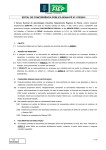
Figure 1
Figure 1 shows the furthermost pixel locations. The upper most left-hand pixel has a coordinate
of 1,1 and the lower most right-hand pixel has a coordinate of 160,80. The X direction goes
across the screen and has a value of 1 to 160 starting from the left-hand side. The Y direction
goes from the top to the bottom of the screen and has a value of 1 to 80 starting at the top.
Touchscreen Calibration
All resistive touchscreens need to go through a “calibration” when they are fitted to an LCD.
This process ensures that the touchscreen data is decoded correctly for a proper screen mapping.
The ideal is to have the touchscreen decoded so that it matches the LCD screen pixel for pixel.
Your ezDISPLAY 2.0 comes pre-calibrated from the factory and more than likely another
calibration will not be needed. However, if you find that the data from the touchscreen is grossly
out-of-range then you can re-calibrate the touchscreen at any time. This is discussed in more
detail in the “Commands” section of this manual. A good test to perform to check for calibration
accuracy is to latch the floating character to the touchscreen. How to do this is also discussed in
the “Commands” section of this manual. Once this is done use a fine-tipped stylus and move it
around the entire touchscreen. The upper left-hand pixel of the floating character should closely
follow where the stylus is touching.
There are many factors that can affect the calibration of the touchscreen. Some common ones
are voltage supplied and temperature. For example, if the touchscreen is calibrated with a
+5VDC supply at room temperature (about 25°C) and then used in a very warm room (40°C) the
calibration will be off since the properties of the touchscreen will have changed with such a great
temperature rise. Also, if the supply voltage is under or above the voltage it was calibrated at
this will affect calibration as well. If the touchscreen was calibrated at +5VDC and then the
ezDISPLAY 2.0 is operated at +4.8VDC then the calibration will be off. For a good calibration
)))))))))))))))))))))))))))))))))))))))
Page 5
Copyright © Multilabs – 2006 All rights reserved
ezDISPLAY 2.0 User Manual
)))))))))))))))))))))))))))))))))))))))
the floating character should be within ±1 or 2 pixels of the stylus. Again, for the most part, if
the ezDISPLAY 2.0 is used in normal room temperatures and a well regulated +5VDC supply is
used then recalibration should never be needed. If the ezDISPLAY 2.0 is going to be used in a
different type of environment then it should be re-calibrated within that environment.
IMPORTANT – It is also recommended that a fine-point stylus be used for calibration.
Using a device with a broad point or a finger will result in an inaccurate calibration.
Communications Protocol
Communications are done through the TTL level Tx and Rx asynchronous data lines. The
protocol is 9600 baud with 8 data bits, 1 stop bit, and no parity. The amount of data sent to the
ezDISPLAY 2.0 is dependant on the command. Data is sent to the ezDISPLAY 2.0 one byte
right after another with no delay. Once the proper amount of data has been received by the
ezDISPLAY 2.0 it will be analyzed and executed and either an ACK (decimal value of 6) or
NAK (decimal value of 21) will be returned. The only exception to this is when the command
for reading the touchscreen is sent. Instead of an ACK being sent the ezDISPLAY 2.0 will send
two bytes of data. Refer to the “Commands” section in this manual for information on the data
that is sent. The ezDISPLAY 2.0 will NAK a command if one of the values is out or range or a
command code is not recognized. For the amount of time it takes for the ezDISPLAY 2.0 to
send a NAK see the “Timing” section in this manual. If the command code is recognized and all
the values are within range then the command will be executed and an ACK will be sent once
completed. Again, for the amount of time it takes for the ezDISPLAY 2.0 to send an ACK see
the “Timing” section in this manual. Another command should not be sent to the ezDISPLAY
2.0 until the ACK is received. Sending another command before the ACK is received might
result in unexpected or incorrect operation.
Timing
When the last byte of a command is sent to the ezDISPLAY 2.0 an ACK or NAK will be
returned as discussed in the “Communications Protocol” section. The only exception to this is
when the command for reading the touchscreen is sent. Instead of an ACK being sent the
ezDISPLAY 2.0 will send two bytes of data. Refer to the “Commands” section in this manual
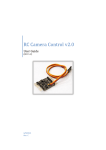
for information on the data that is sent. The following is a timing diagram (Figure 2) followed
by the timing values of the ezDISPLAY 2.0. Figure 1 is valid for all timing values except for
startup which is typically 91mS.
Figure 2
)))))))))))))))))))))))))))))))))))))))
Page 6
Copyright © Multilabs – 2006 All rights reserved
ezDISPLAY 2.0 User Manual
)))))))))))))))))))))))))))))))))))))))
Values for Tdly Sends an NAK (Received either an invalid command code or a value is out of range):
Typically 1gS
Received last byte of Add Character command until an ACK is sent:
Typically 42.3mS
Received last byte of Character Placement command until an ACK is sent:
Typically 6.8mS
Received last byte of Download Screen data until an ACK is sent:
Typically 1gS
Received last byte of Erase Area command until an ACK is sent:
Erase Area
Minimum 258gS & Maximum 875mS
Whole Screen
Typically 27mS
Received last byte of Floating Character command until an ACK is sent:
User Control
Typically 7.9mS
Follow Touchscreen (Latch to Touchscreen)
50gS
Received last byte of Get Touchscreen Data command until the first byte is sent:
Typically 558gS
Receive last byte of Line command until an ACK is sent:
Minimum 150gS & Maximum 10.8mS
Receive last byte of Pixel command until ACK is sent:
Typically 126gS
Received last byte of Retrieve Screen command until ACK is sent:
Typically 388mS
Received last byte of Save Screen command until ACK is sent:
Typically 9S
Received last byte of Touchscreen Calibration command until ACK is sent:
No set time is defined since it is based on the user
Received last byte of Backlight command until ACK is sent:
10gS
)))))))))))))))))))))))))))))))))))))))
Page 7
Copyright © Multilabs – 2006 All rights reserved
ezDISPLAY 2.0 User Manual
)))))))))))))))))))))))))))))))))))))))
Contrast Adjustment
At the front of the module on the left-hand side there is a small knob labeled “CONTRAST”.
This allows you to adjust the contrast of the LCD screen to best suit your operating conditions.
Rotate the knob clockwise and counter-clockwise until the pixels that are on are clear and the
pixels that are off are not visible.
)))))))))))))))))))))))))))))))))))))))
Page 8
Copyright © Multilabs – 2006 All rights reserved
ezDISPLAY 2.0 User Manual
)))))))))))))))))))))))))))))))))))))))
OPERATION COMMANDS
Add Character
This command allows you to define your own custom characters. The character memory map is
setup to allow 128 total characters. Characters 0 through 31 are undefined and 32 through 127
are pre-defined from the factory to a standard ASCII character. Even though this command will
allow you to define custom characters from 0 to 31 you can also change characters 32 through
127. This allows you to define custom fonts or replace ASCII characters that will not be used
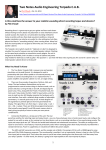
with custom characters. In any case each character is 8 by 8 pixels:
Figure 3
To create a customer character you first draw the image that you want in the 8 by 8 matrix. Once
you have what you want you have to determine a value for each of the eight rows. At the bottom
of each column there is a number starting at 128 under the left-most column. These numbers
represent the value of each pixel that is turned on in that row. To get the byte value for a row
you add up all the values for each pixel that is turned on. For example:
)))))))))))))))))))))))))))))))))))))))
Page 9
Copyright © Multilabs – 2006 All rights reserved
ezDISPLAY 2.0 User Manual
)))))))))))))))))))))))))))))))))))))))
Figure 4
This custom character would be defined by the follow values: 60, 66, 165, 129, 165, 153, 66,
and 60. Data is sent to the ezDISPLAY 2.0 from the top row to the bottom row.
Syntax: code, character #, byte 0, byte 1, byte 2, byte 3, byte 4, byte 5, byte 6, byte 7
• Code is the character that tells the ezDISPLAY 2.0 that this is an Add Character
command. This code is an “A” (decimal value of 65).
• Character # is a value from 0 to 127 that tells the ezDISPLAY 2.0 which character to
define.
• Bytes 0 – 7 are the eight bytes that make up the character bitmap. They are sent to the
ezDISPLAY 2.0 from the top byte to the bottom byte.
)))))))))))))))))))))))))))))))))))))))
Page 10
Copyright © Multilabs – 2006 All rights reserved
ezDISPLAY 2.0 User Manual
)))))))))))))))))))))))))))))))))))))))
Backlight
This command allows you to turn the LED backlight on and off.
Syntax: code, mode
• Code is the character that tells the ezDISPLAY 2.0 that this is a Backlight command.
This code is a “B” (decimal value of 66).
• Mode tells the ezDISPLAY 2.0 what to do with the backlight:
0 – Off
1 – On
)))))))))))))))))))))))))))))))))))))))
Page 11
Copyright © Multilabs – 2006 All rights reserved
ezDISPLAY 2.0 User Manual
)))))))))))))))))))))))))))))))))))))))
Character Placement
This command places a character (either built-in or user-defined) on the screen. The character
can be placed in a variety of different ways depending on your needs. The first option is the
character can be placed in either landscape or portrait. Figure 5 shows an “A” in landscape and
figure 6 shows an “A” in portrait.
Figure 5
Figure 6
Whether in landscape or portrait a character can be placed in regular mode as shown in the
previous figures or in reverse mode as shown in Figure 7.
)))))))))))))))))))))))))))))))))))))))
Page 12
Copyright © Multilabs – 2006 All rights reserved
ezDISPLAY 2.0 User Manual
)))))))))))))))))))))))))))))))))))))))
Figure 7
A character can also be placed as an opaque or as a transparent. When a character is placed as an
opaque all the pixels are drawn. The pixels that are off are turned off and the pixels that are on
are turned on. When drawn this way a character will completely overwrite whatever it is placed
over. When a character is placed as a transparent then the pixels that are off are not drawn. Only
the pixels that are on are drawn. This allows you to place a character over a background and the
background will be visible through the off pixels of the character. Regardless of the options all
characters are placed as a true bitmap. The ezDISPLAY 2.0 has no character cells, any character
can be placed anywhere on the screen. When placing a character you give the ezDISPLAY 2.0
an X and Y coordinate. This coordinate is the starting position of where the character will be
drawn. This coordinate represents the upper left-hand pixel of the character being placed
whether landscape or portrait.
Syntax: code, mode, character #, x, y
• Code is the character that tells the ezDISPLAY 2.0 that this is a Character Placement
command. This code is a “C” (decimal value of 67).
• Mode tells the ezDISPLAY 2.0 how to place the character. There are eight modes:
0 – Landscape, Regular, Opaque
1 – Landscape, Regular, Transparent
2 – Landscape, Reverse, Opaque
3 – Landscape, Reverse, Transparent
4 – Portrait, Regular, Opaque
5 – Portrait, Regular, Transparent
6 – Portrait, Reverse, Opaque
7 – Portrait, Reverse, Transparent
• Character # is a value from 0 to 127 that tells the ezDISPLAY 2.0 which character to
display.
• X is a value from 1 to 160 that indicates the starting x position on the screen.
• Y is a value from 1 to 80 that indicates the starting y position on the screen.
)))))))))))))))))))))))))))))))))))))))
Page 13
Copyright © Multilabs – 2006 All rights reserved
ezDISPLAY 2.0 User Manual
)))))))))))))))))))))))))))))))))))))))
Download Screen
This command allows the ezDISPLAY 2.0 to except screen data from an outside source. The
screen data is in the form of a continuous stream of 1600 bytes. The bitmap of the ezDISPLAY
2.0 is laid out as 80 rows of 20 bytes as shown in Figure 8:
Figure 8
Byte 0 of row 1 represents the upper most left-hand byte of the screen and is the starting position
for the data stream. The first byte of the data stream is placed there and the second byte is placed
at byte 1 of row 1. The bytes are continually placed next to each other down the row. When
byte 19 of row 1 has been placed then the next byte is placed in position byte 0 of row 2. Row 2
is filled left to right and then row 3 all the way until Byte 19 of Row 80 which is the 1600th and
last byte of the data stream. The screen is drawn as the data is received so anything current on
the screen will be erased. This command will also automatically turn off the floating character if
it is on.
Syntax: code, bytes 0 - 1599
• Code is the character that tells the ezDISPLAY 2.0 that this is a Download Screen
command. This code is a “D” (decimal value of 68).
• Bytes 0 - 1599 are the bytes that make up the screen data. They are sent to the
ezDISPLAY 2.0 from the upper left-hand byte to the lower right-hand byte.
)))))))))))))))))))))))))))))))))))))))
Page 14
Copyright © Multilabs – 2006 All rights reserved
ezDISPLAY 2.0 User Manual
)))))))))))))))))))))))))))))))))))))))
Erase Area
This command is used to either erase a portion or the entire screen. When an area is erased all
the pixels in that area are turned off. In the case of erasing the entire screen the whole screen is
cleared. When the entire screen is erased the ezDISPLAY 2.0 will automatically turn off the
floating character if it is on. The floating character is not affected for an area erasure. The area
to be erased is defined by two coordinates that make up a square/rectangular area. The upper
left-hand corner of the area is defined as X1,Y1 and the lower right-hand corner is defined as
X2,Y2.
Area
Syntax: code, mode, x1, y1, x2, y2
• Code is the character that tells the ezDISPLAY 2.0 that this is an Erase Area command.
This code is an “E” (decimal value of 69).
• Mode is 0 and tells the ezDISPLAY 2.0 just to erase an area and not the whole screen.
• X1 is a value from 1 to 160 that indicates the starting x position on the screen.
• Y1 is a value from 1 to 80 that indicates the starting y position on the screen.
• X2 is a value from 1 to 160 that indicates the ending x position on the screen
• Y2 is a value from 1 to 80 that indicates the ending y position on the screen.
Whole Screen
Syntax: code, mode
• Code is the character that tells the ezDISPLAY 2.0 that this is an Erase Area command.
This code is an “E” (decimal value of 69).
• Mode is 1 and tells the ezDISPLAY 2.0 to erase the whole screen.
)))))))))))))))))))))))))))))))))))))))
Page 15
Copyright © Multilabs – 2006 All rights reserved
ezDISPLAY 2.0 User Manual
)))))))))))))))))))))))))))))))))))))))
Floating Character
This command enables you to draw a character that will “float” over the other characters and
graphics on the screen without erasing or disturbing them. This character is special in that it can
be changed on-the-fly with a single command. To move this character or change its appearance
it is not necessary to clear it first, the ezDISPLAY 2.0 takes care of this for you. Just send the
new information and the floating character will be removed from its old position and drawn in
the new position automatically.
The floating character has another special feature. It can either be controlled by the user or it can
be “latched” to the touchscreen and automatically controlled by the ezDISPLAY 2.0. When a
floating character is latched to the touchscreen it will become visible when the touchscreen is
pressed and removed when the screen in not being pressed. While the touchscreen in being
pressed the floating character position is automatically updated without any intervention. The
floating character will follow the stylus/finger around the screen. This makes a great visual
indicator without any work on your part.
Regardless of the mode, user controller or “latched”, the floating character will automatically be
turned off when any of the following commands are executed: Erase Area (only when the whole
screen in erased, an area erasure does not affect the floating character), Retrieve Screen,
Download Screen, and Touchscreen Calibration. After these commands are executed the
floating character will have to be turned back on if needed.
User Controlled
Syntax: code, mode, character #, x, y
• Code is the character that tells the ezDISPLAY 2.0 that this is a Floating Character
command. This code is an “F” (decimal value of 70).
• Mode tells the ezDISPLAY 2.0 how to work with the character:
0 – Off
1 – On and under user control
• Character # is a value from 0 to 127 that tells the ezDISPLAY 2.0 which character to
use.
• X is a value from 1 to 160 that indicates the starting x position on the screen.
• Y is a value from 1 to 80 that indicates the starting y position on the screen.
“Latched” to Touchscreen
Syntax: code, mode, character #
• Code is the character that tells the ezDISPLAY 2.0 that this is a Floating Character
command. This code is an “F” (decimal value of 70).
• Mode tells the ezDISPLAY 2.0 how to work with the character:
2 – Off
3 – On and under touchscreen control
• Character # is a value from 0 to 127 that tells the ezDISPLAY 2.0 which character to
use.
)))))))))))))))))))))))))))))))))))))))
Page 16
Copyright © Multilabs – 2006 All rights reserved
ezDISPLAY 2.0 User Manual
)))))))))))))))))))))))))))))))))))))))
Get Touchscreen Data
Executing this command makes the ezDISPLAY 2.0 transmit the current X and Y touch position
of the touchscreen. The touchscreen is automatically read approximately 10 times a second.
Each time the ezDISPLAY 2.0 performs a touchscreen read the X and Y coordinate of the
current touch position is stored in memory. There is no buffer so the data is erased and updated
on each automatic read. The data is stored as a pixel position value. The X coordinate will have
a value of 1 to 160 and the Y coordinate will have a value of 1 to 80. The accuracy of this data
depends on the object pressing the touchscreen. For example, a fine-point stylus will be more
accurate then a finger press. When a finger presses the touchscreen the touchscreen read will
read toward the center of mass. This varies depending on the finger used, the force of the press,
how the finger is placed on the touchscreen, ect. The accuracy you need depends on your
application. For example, if drawing virtual buttons on the screen for a user to press then they
should be made big enough to accompany a wide range of finger sizes and press forces.
When this command is executed you will receive two bytes from the ezDISPLAY 2.0. The first
is the X coordinate (value of 1 to 160) and then the Y coordinate (value of 1 to 80). If you
receive a 0,0 this indicates that the touchscreen is not currently being pressed.
Syntax: code
• Code is the character that tells the ezDISPLAY 2.0 that this is a Get Touchscreen Data
command. This code is a “G” (decimal value of 71).
)))))))))))))))))))))))))))))))))))))))
Page 17
Copyright © Multilabs – 2006 All rights reserved
ezDISPLAY 2.0 User Manual
)))))))))))))))))))))))))))))))))))))))
Line
This command allows you to draw straight lines either horizontally or vertically. When drawing
horizontally both the Y1 and Y2 values must match. When drawing vertically both the X1 and
X2 values must match. Lines can be drawn both on (visible) and off for erasing a line.
Syntax: code, mode, x1, y1, x2, y2
• Code is the character that tells the ezDISPLAY 2.0 that this is a Line command. This
code is an “L” (decimal value of 76).
• Mode tells the ezDISPLAY 2.0 how to draw the line:
0 – Off
1 – On
• X1 is a value from 1 to 160 that indicates the starting x position on the screen.
• Y1 is a value from 1 to 80 that indicates the starting y position on the screen.
• X2 is a value from 1 to 160 that indicates the ending x position on the screen
• Y2 is a value from 1 to 80 that indicates the ending y position on the screen.
)))))))))))))))))))))))))))))))))))))))
Page 18
Copyright © Multilabs – 2006 All rights reserved
ezDISPLAY 2.0 User Manual
)))))))))))))))))))))))))))))))))))))))
Pixel
This command allows you to control individual pixels on the screen. A pixel can either be
turned on or off.
Syntax: code, mode, x, y
• Code is the character that tells the ezDISPLAY 2.0 that this is a Pixel command. This
code is a “P” (decimal value of 80).
• Mode tells the ezDISPLAY 2.0 how to draw the pixel:
0 – Off
1 – On
• X is a value from 1 to 160 that indicates the x coordinate on the screen.
• Y is a value from 1 to 80 that indicates the y coordinate on the screen.
)))))))))))))))))))))))))))))))))))))))
Page 19
Copyright © Multilabs – 2006 All rights reserved
ezDISPLAY 2.0 User Manual
)))))))))))))))))))))))))))))))))))))))
Retrieve Screen
This command allows you to load one of the four saved screens in the non-volatile memory to
the LCD screen. When this command is executed the entire screen is redrawn and all data on the
current screen will be lost. This command will also automatically turn off the floating character
if it is on.
Syntax: code, screen #
• Code is the character that tells the ezDISPLAY 2.0 that this is a Retrieve Screen
command. This code is an “R” (decimal value of 82).
• Screen # tells the ezDISPLAY 2.0 which screen to load and can be a value of 0 to 3.
)))))))))))))))))))))))))))))))))))))))
Page 20
Copyright © Multilabs – 2006 All rights reserved
ezDISPLAY 2.0 User Manual
)))))))))))))))))))))))))))))))))))))))
Save Screen
This command allows you to save the current LCD screen to one of the four screen pages in the
non-volatile memory.
Syntax: code, screen #
• Code is the character that tells the ezDISPLAY 2.0 that this is a Save Screen command.
This code is an “S” (decimal value of 83).
• Screen # tells the ezDISPLAY 2.0 which screen page to save to and can be a value of 0
to 3.
)))))))))))))))))))))))))))))))))))))))
Page 21
Copyright © Multilabs – 2006 All rights reserved
ezDISPLAY 2.0 User Manual
)))))))))))))))))))))))))))))))))))))))
Touchscreen Calibration
The touchscreen comes pre-calibrated from the factory so you will probably never need this
command. However, if you find the reported touchscreen positions grossly inaccurate or the
ezDISPLAY 2.0 is going to be used in an extreme environment you can use this command to recalibrate the touchscreen. The calibration data is stored in non-volatile memory and is
automatically loaded when power is applied.
When you send the command to the ezDISPLAY 2.0 to enter calibration mode the entire screen
is cleared, the floating character is turned off (if on), and the automatic touchscreen readings are
suspended. Since the screen is cleared during this command all screen data will be lost. It
should be saved to one of the screen memory pages if you need to get it back. IMPORTANT –
It is recommended that a fine-point stylus be used for calibration. Using a device with a
broad point or a finger will result in an inaccurate calibration.
Once the screen is cleared a single pixel will be turned on in the upper left-hand corner as shown
in the following figure:
Figure 9
Press down on this point with your stylus. The pixel will be cleared and when you lift your
stylus off of the touchscreen a pixel in the lower right-hand corner will be drawn:
)))))))))))))))))))))))))))))))))))))))
Page 22
Copyright © Multilabs – 2006 All rights reserved
ezDISPLAY 2.0 User Manual
)))))))))))))))))))))))))))))))))))))))
Figure 10
Press down on this point with your stylus. The pixel will be cleared and the ezDISPLAY 2.0 will
calculate the calibration values. If successful the ezDISPLAY 2.0 will send an ACK (decimal
value of 6). If the calibration could not be done then the ezDISPLAY 2.0 will send a NAK
(decimal value of 21). If this is the case then resend the calibration command and do it again.
Once done, a good test to perform to check for calibration accuracy is to latch the floating
character to the touchscreen. How to do this is also discussed in the “Commands” section of this
manual. Once this is done use a fine-tipped stylus and move it around the entire touchscreen.
The upper left-hand pixel of the floating character should closely follow where the stylus is
touching.
Syntax: code
• Code is the character that tells the ezDISPLAY 2.0 that this is a Touchscreen Calibration
command. This code is a “T” (decimal value of 84).
)))))))))))))))))))))))))))))))))))))))
Page 23
Copyright © Multilabs – 2006 All rights reserved
ezDISPLAY 2.0 User Manual
)))))))))))))))))))))))))))))))))))))))
Limited Warranty
Multilabs warrants to the original consumer purchaser of this product that, for a period of 90
days from the date of purchase, this product will be free from defects in material and
workmanship and will perform in substantial conformity to the description of the product in this
Owner's Manual. This warranty shall not apply to defects or errors caused by misuse or neglect.
If the product is found to be defective in material or workmanship or if the product does not
perform as warranted above during the warranty period, Multilabs will repair it, replace it, or
refund the purchase price. The repair, replacement, or refund that is provided for above shall be
the full extent of Multilabs's liability with respect to this product. For repair or replacement
during the warranty period, contact Multilabs customer service by phone at (949) 458-7625 or
email at [email protected] to receive a return authorization number and return instructions.
Limitations
THE ABOVE WARRANTY IS IN LIEU OF AND MULTILABS DISCLAIMS ALL OTHER
WARRANTIES, WHETHER ORAL OR WRITTEN, EXPRESS OR IMPLIED, INCLUDING
ANY WARRANTY OF MERCHANTABILITY OR FITNESS FOR A PARTICULAR
PURPOSE.
ANY IMPLIED WARRANTY, INCLUDING ANY WARRANTY OF
MERCHANTABILITY OR FITNESS FOR A PARTICULAR PURPOSE, WHICH MAY NOT
BE DISCLAIMED OR SUPPLANTED AS PROVIDED ABOVE SHALL BE LIMITED TO
THE 90 DAYS OF THE EXPRESS WARRANTY ABOVE. NO OTHER REPRESENTATION
OR CLAIM OF ANY NATURE BY ANY PERSON SHALL BE BINDING UPON
MULTILABS OR MODIFY THE TERMS OF THE ABOVE WARRANTY AND
DISCLAIMER. IN NO EVENT SHALL MULTILABS BE LIABLE FOR SPECIAL,
INCIDENTAL, CONSEQUENTIAL OR OTHER DAMAGES RESULTING FROM THE
POSSESSION OR USE OF THIS PRODUCT, INCLUDING WITHOUT LIMITATION
DAMAGE TO PROPERTY AND, TO THE EXTENT PERMITTED BY LAW, PERSONAL
INJURY, EVEN IF MULTILABS KNEW OR SHOULD HAVE KNOWN OF THE
POSSIBILITY OF SUCH DAMAGES.
Some states do not allow limitations on how long an implied warranty lasts and/or the exclusion
or limitation of damages, in which case the above limitations and/or exclusions may not apply to
you. You may also have other legal rights, which may vary from state to state.
)))))))))))))))))))))))))))))))))))))))
Page 24
Copyright © Multilabs – 2006 All rights reserved


![PDF [1] - Dep SAE Soudage, Automatismes et Electronique location](http://vs1.manualzilla.com/store/data/005888267_1-8c649f384f0a877ffbc023ff9f75566c-150x150.png)