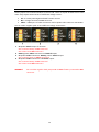
1
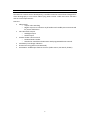
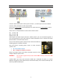
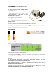
RCCameraControlv2.0
UserGuide
(RCCCv2)
6/9/2013
Rev. C
INTRODUCTION
SmartFPV RC Camera Control board (RCCC) is mul func onal RC control board designed for
Aerial Photography or First Person Video flying. RCCC version 2 adds even more func ons
and has some improvements.
Features:
·
·
·
·
·
·
Video switch
o 3 input video switching
o Regular 3 pin servo connector style headers with middle pins interconnected
for power distribu on
Two LED switch outputs
o Headlight output
o Strobe output
Camera shu er release control
o DSLR and GoPro modes
o Switched or standalone shu er mer with programmable me interval
LiPo ba ery low voltage indica on
Channel mirroring (when sum PPM used)
Sum PPM or 3 PWM input from RC receiver (Video source, LED switch, Shu er)
1
CONNECTIONS
CH1
CH2
CH3
V1
V2
V3
BAT
RC channel 1 (PWM or sum PPM)
RC channel 2
RC channel 3
Video in 1
Video in 2
Video in 3
Ba ery connector
SW
Strobe
Vout
Shu er
Switch headlight output
Switch strobe output
Video output
Shu er connector
CAUTION!
· There is NO reverse polarity protec on and it is physically possible to connect
connectors reversed! Please be careful with connec ons.
· Isolate bard from short circuits using heatshrink if placing near metallic elements!
· All connectors have GND pin on le side if facing connectors and board with
components on top.
2
RC INPUTS
RCCC automa cally detects type of RC signal regular
PWM or sum PPM.
3 PWM inputs
To use device with regular servo outputs from RC
receiver (PWM) connect RCCC to according channels
of your RC receiver. Default func ons of RCCC
channels are:
CH1
CH2
CH3
Video switch
LED switch
Shu er control
Func on mapping to channels can be changed in
Setup mode (see page 10).
PPM input
Connect your RC receiver sum PPM output to RCCC CH1 connector.
RCCC can accept up to 16 PPM channels. Up to three of them will be used.
You can configure channel func ons in Setup mode. Default channel func on if RCCC is used
with PPM:
Video switch
CH7
LED switch
CH8
Shu er control CH9
Channel MIX
You can enable different channel mixes to use one channel for 2 func ons. This will allow
reducing RC system channels used and use them for different func ons.
There are 2 types of mixes:
·
·
3 posi on mix
9 posi on mixes
In 3 Posi on MIX one channel (CH1 in regular PWM mode or, Video control channel in sum
PPM mode) using 3 posi on switch is used to control video switch and LED switch func ons.
3 posi on switch must be set to middle posi on (1.5ms pulse). When switched to one of side
posi ons and back, video switch source is changed. When switched to other side posi on
and back, LED switch state changes. Video switch source and LED switch modes can be
changed through all 3 states cyclic.
Video switch:
Video 1
Video 2
Video 3
Video 1
…
LED switch:
LED’s OFF
Strobe ON
Strobe and Headlight ON
LED’s OFF
…
3
In 9 posi on MIX one channel is divided in 9 posi ons and used to control 2 func ons of
RCCC.
There are 3 MIX combina ons available:
MIX
Func on 1
Func on 2
Video+LED
Video switch
LED switch
Video+Shu er
Video switch
Shu er control
Shu er+LED
Shu er control
LED switch
Channel used when MIX is ac vated is channel that is configured for Func on #1 used in
MIX.
Using mixes in RC transmi er you can combine by example two 3 posi on switches to 9
posi ons of one control channel:
Channel pulse
1.000ms
1.125ms
1.250ms
1.375ms
1.500ms
1.625ms
1.750ms
1.875ms
2.000ms
Func on 1
1
1
1
2
2
2
3
3
3
Func on 2
1
2
3
1
2
3
1
2
3
To set mixes on your RC transmi er you need to follow its user manual.
Channel mirroring
If you are using sum PPM signal to control RCCC, you can output any 2 channels from PPM
stream to CH2 and CH3 connectors. Please see Setup mode how to configure.
This is useful to reduce cables to RC receiver if connec ng camera pan/ lt servos.
You can have cameras, video transmi er, RCCC and pa n/ lt servos placed in some distance
from RC receiver and use only one PPM cable from RC receiver and one cable from ba ery
and have fully func onal video system with minimum of cables used.
By default middle 5V pin of RCCC CH1 cable is not connected to
CH2 and CH3 connector middle pins to avoid short circuit.
In order to power servos connected to CH2 and CH3, you need to
solder together pads of solder jumper shown in picture under
board.
4
VIDEO SWITCH
Connect video sources (video camera, photo camera …) to video input connectors V1-V3.
Connect video transmi er to video output Vout.
You can use 3 state switch to switch between all 3 video sources or 2 state switch to select
between 2 video sources.
Video source is selected based on video control channel value:
0% (1.0ms) V1
50% (1.5ms) V3
100% (2.0ms) V2
Video inputs and video output connector middle “power” pins are connected together so
you can feed power for your video camera or video transmi er to one connector and have
powered other connected video devices.
You can also choose to power cameras and/or video transmi er by
soldering jumpers in bo om of board.
That will connect according power source to video connector
“power” pins:
·
·
5V – 5V from RC receiver
Bat – voltage from ba ery connector
Please read video camera and video transmi er manuals to find
voltage needed to power them.
WARNNG!
Do not solder together both jumpers 5V and Bat if ba ery connected to Bat
connector.
If video cable 3 pin servo style connector middle pin is dedicated for audio, or it needs
different voltage than other video devices connected to RCCC, then remove middle pin and
leave only GND and video pins.
5
LED SWITCH
Connect ba ery to Bat connector. Connect headlight LEDs to switch output connector Sw.
Connect strobe LEDs to Strobe connector.
WARNING!
Use LEDs that are dedicated to voltage you are connec ng to Bat connector.
You can use 2 or 3 state switch to control switch output. Switch has 3 states depending on
control channel value:
0%
(1.0ms) Both switch outputs OFF
50% (1.5ms) Strobe output ac ve (2 impulses every second) and headlight output OFF
100% (2.0ms) Strobe output ac ve (2 impulses every second) and headlight output
steady ON
Switch output has permanent connec on of + pin from Bat connector + pin. Ground pin is
switched. Switch can handle 2A con nuous current and 4A current for 10s.
WARNING!
Please follow polarity!
6
CAMERA SHUTTER
DSLR mode
C – Common
F – Focus
S – Shu er
Connect camera shu er cable to RCCC board. If you use
original SmartFPV shu er cables then connect them so
that connector contacts are seen if looking from top of
the board like in picture.
Use 3 state switch for Focus and Shu er control or 2
state switch for immediate Shu er control.
You can use RCCC shu er func on with all C3 plug and
2.5mm plug Canon cameras, Nikon cameras, GoPro
HERO and HERO2 (HERO3 not fully compa ble) and
other cameras.
Shu er control for DSLR cameras works just like regular
shu er release bu on (Focus and Shu er). Shu er
control for GoPro cameras just turns ON/OFF camera
(see details in GoPro mode descrip on).
You can also make your own cable for camera shu er.
Some informa on about shu er connector pin outs:
h p://www.cameraaxe.com/wiki/index.php? tle=CameraCables
h p://www.doc-diy.net/photo/remote_pinout/
7
GoPro mode
C – Ground
F – Mode
S – Mode
GoPro mode
To enable GoPro mode you have to configure it in setup step 2.
Shu er control in GoPro mode turns ON and OFF GoPro camera. To start recording a er
power ON you have to put GoPro in One Bu on Mode (see GoPro user manual).
It is possible to change way you turn GoPro ON and OFF by enabling GoPro toggle mode in
setup.
If GoPro toggle mode is disabled GoPro follows state of RC transmi er switch dedicated to
shu er control. If switch is ON then GoPro will turn ON, if switch is OFF then GoPro will turn
OFF.
If GoPro toggle mode is enabled then GoPro will change its power state each me when
switch is changed from OFF to ON state. This is usable if you have momentary switch on your
RC transmi er (like Trainer swi tch). Pushing switch will turn GoPro ON, pushing switch one
more me will turn GoPro OFF.
DSLR shu er mer
It is possible to configure DSLR camera shu er to trigger camera with defined me period
using configurable mer func on. Shu er mer is not available for GoPro shu er func on.
Timer is configured in Setup mode and can be set to: 1s, 5s, 10s, 30s, 1min, 5min.
Shu er mer is configurable to start when switched by shu er switch on RC transmi er or
to start automa c when RCCC powers ON and RC signal is detected (standalone mer). If
mer is configured as standalone, you will have one free channel that will not be used for
shu er func on.
It is possible to manually trigger shu er while shu er mer is enabled. This is possible with
3 different shu er control channel values using 3 posi on switch.
Channel values when shu er mer func on is enabled:
0%
(1.0ms) Shu er OFF
50% (1.5ms) Forced shu er
100% (2.0ms) Shu er mer ON
Please see Setup mode how to configure shu er mer func on.
8
LOW BATTERY DETECTION
If enabled in setup device will automa cally detect LiPo ba ery cell count on power up if
ba ery is connected to Bat connector and flash blue LED and LED switch headlight output
number of mes equal to LiPo ba ery cell count detected. RCCC can measure LiPo ba eries
from 1S to 4S
During opera on RCCC board monitors voltage of ba ery. If ba ery voltage falls below
warning level LED switch headlight output will be toggled approximately once per second.
When voltage falls below cri cal level LED switch headlight output will be toggled rapidly.
You can see low ba ery warning from ground while you are flying.
Warning level is 3.5V per cell and cri cal warning level is 3.33V per cell. So for 3S LiPo
ba ery that will be 10.5V and 10V
9
START USING DEVICE
RCCC is powered from CH1 input that is connected to RC receiver.
You can use 6 volt BEC or ESC to power RCCC board.
When device is powered it starts wai ng for valid control signal from RC receiver indica ng
this state by slowly flashing LED.
A er valid signal from RC receiver is detected LED goes OFF.
If ba ery monitor is enabled blue LED together with LED switch headlight output flashes
number of mes according to LiPo cell count detected.
CONFIGURING DEVICE
To configure RCCC you have to enter Setup mode.
Setup mode can be enabled by connec ng RCCC
CH1 to RC receiver, connec ng CH2 and CH3
signal pins together using jumper and then
powering on RCCC and RC transmi er. Setup
mode is indicated with fast flashes a er RCCC
detects signal from RC receiver.
Before setup you must configure switches on RC transmi er for needed RCCC func ons.
Setup mode is slightly different if using sum PPM or regular servo connec on to RC receiver.
Regular PWM mode
Channel connected to RCCC’s CH1 is used as enable channel to enter submenus and change
op ons.
Sum PPM
If using sum PPM to control RCCC Enable channel is used to enter submenus and change
op ons. It is recommended to use one of RC transmi er s cks as Enable channel.
Enable channel is set a er entering setup mode (fast flashes) . You have to move 4 mes
s ck on RC transmi er from one end to other un l LED on RCCC board flashes one me.
A er Enable channel is set, setup menu is entered.
Setup menu
Blue LED flashes long number of mes according configura on menu item number. A er
flashes you have 4 seconds to enter configura on step by changing enable channel state.
If you wait 4 seconds then next menu item number is flashed …
When entered submenu blue LED flashes fast number or mes according submenu item
number. A er flashes you have 4 seconds to enable this op on by changing enable channel
state.
10
Setup menu structure
Menu item
1 Channel setup
2 Shu er setup
3 Ba ery monitor
4 Mix setup
5 Default Se ngs
6 Mirror setup
1
2
3
1
2
3
4
5
6
7
8
9
10
11
12
1
2
1
2
3
4
5
1
1
2
Submenu item
Video CH
Switch CH
Shu er CH
GoPro mode
GoPro toggle mode
Regular DSLR mode
Timer OFF
Switched mer
Standalone mer
Timer 1s
5s
10s
30s
1min
5min
Low bat monitor OFF
Low bat monitor ON
Mix OFF
Video+Switch 3pos MIX
Video+Switch 9pos MIX
Video+Shu er 9pos MIX
Shu er+Switch 9pos MIX
Reset to default se ngs
Mirror CH2
Mirror CH3
Notes
Toggle 4x in 4s,
then 2s for OFF state
(Disabled if not set)
Exits submenu
Exits submenu
Exits submenu
Exits submenu
Exits submenu
Exits submenu
Exits Setup
Cycle 4x in 4s
(Only if PPM used)
1 Channel setup
In this step you configure channels used to control func ons of RCCC.
When entered channel setup using regular servo channels (PWM) for control LED flashes
fast for 30s. That gives you me to remove jumper and connect RC receiver to RCCC CH2 and
CH3.
When entered channel setup blue LED blinks number of submenu according to func on
which channel is being configured. A er these blinks you have 4 seconds to toggle 4 mes
switch on RC transmi er which will be used for this func on. A er toggling 4 mes LED
flashes and you have 2 seconds to leave switch in default state which is Video 1 for video
switch, LED’s OFF for LED switch and Shu er OFF for shu er func on.
If you don’t toggle switch 4 mes during these 4 seconds, this func on will be disabled.
2 Shu er setup
In this step shu er func ons are configured. A er LED blinks number of submenu item you
have 4 seconds to change enable channel state which is RCCC’s CH1 or preconfigured
channel if sum PPM mode is used.
There are several submenu items a er enabling which submenu is exited to main menu
items because enabled op ons are not used with next items (GoPro mode and mer for
example). Submenu is exited also if by example GoPro mode has been configured pre viously
11
and you don’t enable regular DSLR mode (next func ons are not used with GoPro shu er
mode).
See page 7 for more informa on.
3 Ba ery monitor
In this step low ba ery monitoring func on is enabled or disabled. See page 9 for more
informa on.
4 Mix setup
In this step RC channel mix func ons are configured. See page 3 for more informa on.
5 Default se ngs
In this step all se ngs are reset to default factory values:
Channel func ons:
Video switch
LED switch
Shu er control
Regular servo channels (PWM) Sum PPM channels
CH1
CH7
CH2
CH8
CH3
CH9
DSLR shu er mode without mer
Ba ery monitoring disabled
Channel mixing disabled
PPM channel mirroring disabled
6 Mirror setup
In this step sum PPM channel mirroring is configured.
In each of mirror setup submenu items you have 4 seconds to cycle 4 mes from one end to
other (1ms-2ms pulse) channel on RC transmi er which will be mirrored to according
output. A er you cycle 4 mes channel, LED blinks accep ng channel for mirroring.
If you don’t cycle channel 4 mes during these 4 seconds, mirroring to according output will
be disabled.
See page 4 for more informa on.
NOTE!
Remember to remove jumper used to enter setup mode.
12
VOLTAGE SOLDER JUMPERS
Solder jumpers are located on bo om of device PCB. There are 4 pads located close to each
other. They expose contact area s of 3 different voltage circuits:
·
·
·
5V – 5-6 volts powering RCCC board from RC receiver.
Bat – voltage connected to Bat connector
Video – middle pins of video connectors used to power video camera or transmi er
You can solder neighbor pads to have different voltage connec ons:
1. 5V power Switch output for 5V LEDs.
Don’t connect ba ery to Bat connector!
Don’t short circuit Bat connector!
2. Ba ery power Video connectors and Switch output.
3. 5V powers Video connectors. Ba ery powers Switch output.
Don’t connect power to Video connectors!
4. 5V powers Video connectors and Switch output.
Don’t connect ba ery to Bat connector!
Don’t short circuit Bat connector!
WARNNG!
Do not solder together both jumpers 5V and Bat if ba ery connected to Bat
connector.
13
RCCC v2.0 QUICK GUIDE
CH1
CH2
CH3
V1
V2
V3
BAT
RC channel 1 (PWM or sum PPM)
RC channel 2
RC channel 3
Video in 1
Video in 2
Video in 3
Ba ery connector
SW
Strobe
Vout
Shu er
Switch headlight output
Switch strobe output
Video output
Shu er connector
SOLDER JUMPERS
1.
2.
3.
4.
5.
5V power Switch output for 5V LEDs.
Don’t connect ba ery to Bat connector!
Don’t short circuit Bat connector!
Ba ery power Video connectors and Switch output.
5V powers Video connectors. Ba ery powers Switch output.
Don’t connect power to Video connectors!
5V powers Video connectors and Switch output.
Don’t connect ba ery to Bat connector!
Don’t short circuit Bat connector!
CH2 and CH3 powers RCCC board.
WARNNG!
Do not solder together both jumpers 5V and
Bat if ba ery connected to Bat connector.
SETUP MENU
Menu item
1 Channel setup
2 Shu er setup
1
2
3
1
2
3
4
5
6
7
8
9
10
11
12
Submenu item
Video CH
Switch CH
Shu er CH
GoPro mode
GoPro toggle mode
Regular DSLR mode
Timer OFF
Switched mer
Standalone mer
Timer 1s
5s
10s
30s
1min
5min
14
3
Ba ery monitor
4
Mix setup
5
6
Default Se ngs
Mirror setup
1
2
1
2
3
4
5
1
1
2
Low bat monitor OFF
Low bat monitor ON
Mix OFF
Video+Switch 3pos MIX
Video+Switch 9pos MIX
Video+Shu er 9pos MIX
Shu er+Switch 9pos MIX
Reset to default se ngs
Mirror CH2
Mirror CH3