1
SECTION 2
INTRODUCTION
The section provide a brief introduction to the M68000 microprocessors (MPUs).
Detailed information on the programming model, data types, addressing modes, data
organization and instruction set can be found in M68000PM/AD, M68000 Programmer's
Reference Manual. All the processors are identical from the programmer's viewpoint,
except that the MC68000 can directly access 16 Mbytes (24-bit address) and the
MC68008 can directly access 1 Mbyte (20-bit address on 48-pin version or 22-bit
address on 52-pin version). The MC68010, which also uses a 24-bit address, has much
in common with the other devices; however, it supports additional instructions and
registers and provides full virtual machine/memory capability. Unless noted, all
information pertains to all the M68000 MPUs.
2.1
PROGRAMMER'S MODEL
All the microprocessors executes instructions in one of two modes—user mode or
supervisor mode. The user mode provides the execution environment for the majority of
application programs. The supervisor mode, which allows some additional instructions
and privileges, is used by the operating system and other system software.
2.1.1 User' Programmer's Model
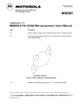
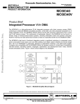
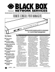
The user programmer's model (see Figure 2-1) is common to all M68000 MPUs. The
user programmer's model, contains 16, 32-bit, general-purpose registers (D0–D7, A0–
A7), a 32-bit program counter, and an 8-bit condition code register. The first eight
registers (D0–D7) are used as data registers for byte (8-bit), word (16-bit), and long-word
(32-bit) operations. The second set of seven registers (A0–A6) and the user stack pointer
(USP) can be used as software stack pointers and base address registers. In addition,
the address registers can be used for word and long-word operations. All of the 16
registers can be used as index registers.
MOTOROLA
M68000 8-/16-/32-BIT MICROPROCESSOR USER’S MANUAL
2-1
31
16 15
8 7
0
D0
D1
D2
D3
EIGHT
DATA
REGISTERS
D4
D5
D6
D7
31
16 15
0
A0
A1
A2
SEVEN
ADDRESS
REGISTERS
A3
A4
A5
A6
A7
USER STACK
(USP) POINTER
31
0
7
PC
PROGRAM
COUNTER
CCR
STATUS
REGISTER
0
Figure 2-1. User Programmer's Model
(MC68000/MC68HC000/MC68008/MC68010)
2.1.2 Supervisor Programmer's Model
The supervisor programmer's model consists of supplementary registers used in the
supervisor mode. The M68000 MPUs contain identical supervisor mode register
resources, which are shown in Figure 2-2, including the status register (high-order byte)
and the supervisor stack pointer (SSP/A7').
31
16 15
0
A7'
SUPERVISOR STACK
(SSP) POINTER
15
8 7
0
CCR
SR
STATUS REGISTER
Figure 2-2. Supervisor Programmer's Model Supplement
The supervisor programmer's model supplement of the MC68010 is shown in Figure 23. In addition to the supervisor stack pointer and status register, it includes the vector
base register (VRB) and the alternate function code registers (AFC).The VBR is used to
determine the location of the exception vector table in memory to support multiple vector
2-2
M68000 8-/16-/32-BIT MICROPROCESSOR USER’S MANUAL
MOTOROLA
tables. The SFC and DFC registers allow the supervisor to access user data space or
emulate CPU space cycles.
31
16 15
15
0
8 7
A7'
(SSP)
SUPERVISOR STACK
POINTER
SR
STATUS REGISTER
VBR
VECTOR BASE REGISTER
SFC
ALTERNATE FUNCTION
CODE REGISTERS
0
CCR
31
0
2
0
DFC
Figure 2-3. Supervisor Programmer's Model Supplement
(MC68010)
2.1.3 Status Register
The status register (SR),contains the interrupt mask (eight levels available) and the
following condition codes: overflow (V), zero (Z), negative (N), carry (C), and extend (X).
Additional status bits indicate that the processor is in the trace (T) mode and/or in the
supervisor (S) state (see Figure 2-4). Bits 5, 6, 7, 11, 12, and 14 are undefined and
reserved for future expansion
SYSTEM BYTE
15
13
T
S
USER BYTE
10
8
I2 I1 I0
4
X
0
N Z V
C
TRACE MODE
EXTEND
NEGATIVE
ZERO
OVERFLOW
CARRY
SUPERVISOR
STATE
INTERRUPT
MASK
CONDITION
CODES
Figure 2-4. Status Register
2.2
DATA TYPES AND ADDRESSING MODES
The five basic data types supported are as follows:
1. Bits
2. Binary-Coded-Decimal (BCD) Digits (4 Bits)
3. Bytes (8 Bits)
4. Words (16 Bits)
5. Long Words (32 Bits)
MOTOROLA
M68000 8-/16-/32-BIT MICROPROCESSOR USER’S MANUAL
2-3
In addition, operations on other data types, such as memory addresses, status word
data, etc., are provided in the instruction set.
The 14 flexible addressing modes, shown in Table 2-1, include six basic types:
1. Register Direct
2. Register Indirect
3. Absolute
4. Immediate
5. Program Counter Relative
6. Implied
The register indirect addressing modes provide postincrementing, predecrementing,
offsetting, and indexing capabilities. The program counter relative mode also supports
indexing and offsetting. For detail information on addressing modes refer to
M68000PM/AD, M68000 Programmer Reference Manual.
2-4
M68000 8-/16-/32-BIT MICROPROCESSOR USER’S MANUAL
MOTOROLA
Table 2-1. Data Addressing Modes
Mode
Syntax
Register Direct Addressing
Data Register Direct
Address Register Direct
EA=Dn
EA=An
Dn
An
Absolute Data Addressing
Absolute Short
Absolute Long
EA = (Next Word)
EA = (Next Two Words)
(xxx).W
(xxx).L
EA = (PC)+d16
EA = (PC)+d8
(d16,PC)
(d8,PC,Xn)
EA = (An)
EA = (An), An ← An+N
An ¯ An–N, EA=(An)
EA = (An)+d16
EA = (An)+(Xn)+d8
(An)
(An)+
-(An)
(d16,An)
(d8,An,Xn)
DATA = Next Word(s)
Inherent Data
#<data>
EA = SR, USP, SSP, PC,
VBR, SFC, DFC
SR,USP,SSP,PC,
VBR, SFC,DFC
Program Counter Relative
Addressing
Relative with Offset
Relative with Index and Offset
Register Indirect Addressing
Register Indirect
Postincrement Register Indirect
Predecrement Register Indirect
Register Indirect with Offset
Indexed Register Indirect with Offset
Immediate Data Addressing
Immediate
Quick Immediate
Implied Addressing 1
Implied Register
NOTES:
2.3
Generation
1. The VBR, SFC, and DFC apply to the MC68010 only
EA = Effective Address
Dn = Data Register
An = Address Register
()
= Contents of
PC = Program Counter
d8
= 8-Bit Offset (Displacement)
d16 = 16-Bit Offset (Displacement)
N
= 1 for byte, 2 for word, and 4 for long word. If An is the stack pointer and
the operand size is byte, N = 2 to keep the stack pointer on a word boundary.
¯
= Replaces
Xn = Address or Data Register used as Index Register
SR = Status Register
USP = User Stack Pointer
SSP = Supervisor Stack Pointer
CP = Program Counter
VBR = Vector Base Register
DATA ORGANIZATION IN REGISTERS
The eight data registers support data operands of 1, 8, 16, or 32 bits. The seven address
registers and the active stack pointer support address operands of 32 bits.
2.3.1 Data Registers
Each data register is 32 bits wide. Byte operands occupy the low-order 8 bits, word
operands the low-order 16 bits, and long-word operands, the entire 32 bits. The least
significant bit is addressed as bit zero; the most significant bit is addressed as bit 31.
MOTOROLA
M68000 8-/16-/32-BIT MICROPROCESSOR USER’S MANUAL
2-5
When a data register is used as either a source or a destination operand, only the
appropriate low-order portion is changed; the remaining high-order portion is neither
used nor changed.
2.3.2 Address Registers
Each address register (and the stack pointer) is 32 bits wide and holds a full, 32-bit
address. Address registers do not support byte-sized operands. Therefore, when an
address register is used as a source operand, either the low-order word or the entire
long-word operand is used, depending upon the operation size. When an address
register is used as the destination operand, the entire register is affected, regardless of
the operation size. If the operation size is word, operands are sign-extended to 32 bits
before the operation is performed.
2.4
DATA ORGANIZATION IN MEMORY
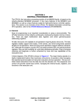
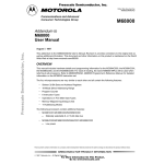
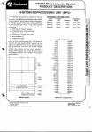
Bytes are individually addressable. As shown in Figure 2-5, the high-order byte of a
word has the same address as the word. The low-order byte has an odd address, one
count higher. Instructions and multibyte data are accessed only on word (even byte)
boundaries. If a long-word operand is located at address n (n even), then the second
word of that operand is located at address n+2.
15
14
13
12
11
BYTE 000000
$000002
BYTE 000002
$FFFFFE
10
9
8
7
6
5
4
3
2
1
0
WORD 0
ADDRESS
$000000
BYTE 000001
WORD 1
BYTE 000003
WORD 7FFFFF
BYTE FFFFFE
BYTE FFFFFE
Figure 2-5. Word Organization in Memory
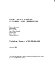
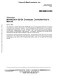
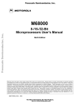
The data types supported by the M68000 MPUs are bit data, integer data of 8, 16, and
32 bits, 32-bit addresses, and binary-coded-decimal data. Each data type is stored in
memory as shown in Figure 2-6. The numbers indicate the order of accessing the data
from the processor. For the MC68008 with its 8-bit bus, the appearance of data in
memory is identical to the all the M68000 MPUs. The organization of data in the memory
of the MC68008 is shown in Figure 2-7.
2-6
M68000 8-/16-/32-BIT MICROPROCESSOR USER’S MANUAL
MOTOROLA
7
15
14
13
12
11
6
BIT DATA
1 BYTE = 8 BITS
5
4
3
2
1
0
10
INTEGER DATA
1 BYTE = 8 BITS
9
8
7
6
5
4
BYTE 0
MSB
14
13
12
11
2
1
0
2
1
0
BYTE 1
LSB
BYTE 2
15
3
BYTE 3
1 WORD = 16 BITS
9
8
7
6
10
5
4
3
WORD 0
MSB
LSB
WORD 1
WORD 2
EVEN BYTE
7
ODD BYTE
6
5
4
3
2
15
14
MSB
13
12
11
10
1
0
7
6
1 LONG WORD = 32 BITS
9
8
7
6
5
4
3
2
1
0
5
4
3
2
1
0
HIGH ORDER
LONG WORD 0
LOW ORDER
LSB
LONG WORD 1
LONG WORD 2
15
14
MSB
13
12
11
10
ADDRESSES
1 ADDRESS = 32 BITS
9
8
7
6
5
4
3
2
1
0
HIGH ORDER
ADDRESS 0
LOW ORDER
LSB
ADDRESS 1
ADDRESS 2
MSB = MOST SIGNIFICANT BIT
LSB = LEAST SIGNIFICANT BIT
15
14
MSD
13
12
DECIMAL DATA
2 BINARY-CODED-DECIMAL DIGITS = 1 BYTE
11
10
9
8
7
6
5
4
BCD 0
BCD 1
BCD 4
BCD 5
LSD
3
2
BCD 2
BCD 3
BCD 6
BCD 7
1
0
MSD = MOST SIGNIFICANT DIGIT
LSD = LEAST SIGNIFICANT DIGIT
Figure 2-6. Data Organization in Memory
MOTOROLA
M68000 8-/16-/32-BIT MICROPROCESSOR USER’S MANUAL
2-7
7
6
BIT DATA 1 BYTE = 8 BITS
5
4
3
2
1
0
7
6
INTEGER DATA 1 BYTE = 8 BITS
5
4
3
2
1
0
BYTE 0
LOWER ADDRESSES
BYTE 1
BYTE 2
HIGHER ADDRESSES
BYTE 3
1 WORD = 2 BYTES = 16 BITS
LOWER ADDRESSES
BYTE 0 (MS BYTE)
WORD 0
BYTE 1 (LS BYTE)
BYTE 0 (MS BYTE)
WORD 1
BYTE 1 (LS BYTE)
HIGHER ADDRESSES
1 LONG WORD = 2 WORDS = 4 BYTES = 32 BITS
BYTE 0
HIGH-ORDER
WORD
BYTE 1
LOWER ADDRESSES
LONG WORD 0
BYTE 2
LOW-ORDER
WORD
BYTE 3
BYTE 0
HIGH-ORDER
WORD
BYTE 1
LONG WORD 1
BYTE 2
BYTE 3
LOW-ORDER
WORD
HIGHER ADDRESSES
Figure 2-7. Memory Data Organization of the MC68008
2.5
INSTRUCTION SET SUMMARY
Table 2-2 provides an alphabetized listing of the M68000 instruction set listed by
opcode, operation, and syntax. In the syntax descriptions, the left operand is the source
operand, and the right operand is the destination operand. The following list contains the
notations used in Table 2-2.
2-8
M68000 8-/16-/32-BIT MICROPROCESSOR USER’S MANUAL
MOTOROLA
Notation for operands:
PC —
SR —
V—
Immediate Data —
Source —
Destination —
Vector —
+inf —
–inf —
<fmt> —
Program counter
Status register
Overflow condition code
Immediate data from the instruction
Source contents
Destination contents
Location of exception vector
Positive infinity
Negative infinity
Operand data format: byte (B), word (W), long (L), single
(S), double (D), extended (X), or packed (P).
FPm — One of eight floating-point data registers (always
specifies the source register)
FPn — One of eight floating-point data registers (always
specifies the destination register)
Notation for subfields and qualifiers:
<bit> of <operand> — Selects a single bit of the operand
<ea>{offset:width} — Selects a bit field
(<operand>) — The contents of the referenced location
<operand>10 — The operand is binary-coded decimal, operations are
performed in decimal
(<address register>) — The register indirect operator
–(<address register>) — Indicates that the operand register points to the memory
(<address register>)+ — Location of the instruction operand—the optional mode
qualifiers are –, +, (d), and (d, ix)
#xxx or #<data> — Immediate data that follows the instruction word(s)
Notations for operations that have two operands, written <operand> <op> <operand>,
where <op> is one of the following:
→
↔
+
–
—
—
—
—
×—
÷—
<—
>—
V—
⊕—
Λ—
MOTOROLA
The source operand is moved to the destination operand
The two operands are exchanged
The operands are added
The destination operand is subtracted from the source
operand
The operands are multiplied
The source operand is divided by the destination
operand
Relational test, true if source operand is less than
destination operand
Relational test, true if source operand is greater than
destination operand
Logical OR
Logical exclusive OR
Logical AND
M68000 8-/16-/32-BIT MICROPROCESSOR USER’S MANUAL
2-9
shifted by, rotated by — The source operand is shifted or rotated by the number of
positions specified by the second operand
Notation for single-operand operations:
~<operand> — The operand is logically complemented
<operand>sign-extended — The operand is sign-extended, all bits of the upper
portion are made equal to the high-order bit of the lower
portion
<operand>tested — The operand is compared to zero and the condition
codes are set appropriately
Notation for other operations:
TRAP — Equivalent to Format/Offset Word → (SSP); SSP–2 →
SSP; PC → (SSP); SSP–4 → SSP; SR → (SSP);
SSP–2 → SSP; (vector) → PC
STOP — Enter the stopped state, waiting for interrupts
If <condition> then — The condition is tested. If true, the operations after "then"
<operations> else
are performed. If the condition is false and the optional
<operations>
"else" clause is present, the operations after "else" are
performed. If the condition is false and else is omitted, the
instruction performs no operation. Refer to the Bcc
instruction description as an example.
2-10
M68000 8-/16-/32-BIT MICROPROCESSOR USER’S MANUAL
MOTOROLA
Table 2-2. Instruction Set Summary (Sheet 1 of 4)
Opcode
Operation
Syntax
Source10 + Destination10 + X → Destination
ABCD Dy,Dx
ABCD –(Ay), –(Ax)
ADD
Source + Destination → Destination
ADD <ea>,Dn
ADD Dn,<ea>
ADDA
Source + Destination → Destination
ADDA <ea>,An
ADDI
Immediate Data + Destination → Destination
ADDI # <data>,<ea>
ADDQ
Immediate Data + Destination → Destination
ADDQ # <data>,<ea>
ADDX
Source + Destination + X → Destination
ADDX Dy, Dx
ADDX –(Ay), –(Ax)
AND
Source Λ Destination → Destination
AND <ea>,Dn
AND Dn,<ea>
ANDI
Immediate Data Λ Destination → Destination
ANDI # <data>, <ea>
ABCD
ANDI to CCR Source Λ CCR → CCR
ANDI to SR
ANDI # <data>, CCR
If supervisor state
then Source Λ SR → SR
else TRAP
ANDI # <data>, SR
Destination Shifted by <count> → Destination
ASd Dx,Dy
ASd # <data>,Dy
ASd <ea>
If (condition true) then PC + d → PC
Bcc <label>
BCHG
~ (<number> of Destination) → Z;
~ (<number> of Destination) → <bit number> of Destination
BCHG Dn,<ea>
BCHG # <data>,<ea>
BCLR
~ (<bit number> of Destination) → Z;
0 → <bit number> of Destination
BCLR Dn,<ea>
BCLR # <data>,<ea>
BKPT
Run breakpoint acknowledge cycle;
TRAP as illegal instruction
BKPT # <data>
PC + d → PC
BRA <label>
~ (<bit number> of Destination) → Z;
1 → <bit number> of Destination
BSET Dn,<ea>
BSET # <data>,<ea>
BSR
SP – 4 → SP; PC → (SP); PC + d → PC
BSR <label>
BTST
– (<bit number> of Destination) → Z;
BTST Dn,<ea>
BTST # <data>,<ea>
CHK
If Dn < 0 or Dn > Source then TRAP
CHK <ea>,Dn
ASL, ASR
Bcc
BRA
BSET
CLR
0 → Destination
CLR <ea>
CMP
Destination—Source → cc
CMP <ea>,Dn
CMPA
Destination—Source
CMPA <ea>,An
CMPI
Destination —Immediate Data
CMPI # <data>,<ea>
CMPM
Destination—Source → cc
CMPM (Ay)+, (Ax)+
DBcc
If condition false then (Dn – 1 → Dn;
If Dn ≠ –1 then PC + d → PC)
DBcc Dn,<label>
MOTOROLA
M68000 8-/16-/32-BIT MICROPROCESSOR USER’S MANUAL
2-11
Table 2-2. Instruction Set Summary (Sheet 2 of 4)
Opcode
Operation
Syntax
DIVS
Destination/Source → Destination
DIVS.W <ea>,Dn
32/16 → 16r:16q
DIVU
Destination/Source → Destination
DIVU.W <ea>,Dn
32/16 → 16r:16q
EOR
Source ⊕ Destination → Destination
EOR Dn,<ea>
EORI
Immediate Data ⊕ Destination → Destination
EORI # <data>,<ea>
EORI to CCR Source ⊕ CCR → CCR
EORI to SR
EORI # <data>,CCR
If supervisor state
then Source ⊕SR → SR
else TRAP
EORI # <data>,SR
EXG
Rx ↔ Ry
EXG Dx,Dy
EXG Ax,Ay
EXG Dx,Ay
EXG Ay,Dx
EXT
Destination Sign-Extended → Destination
EXT.W Dn
EXT.L Dn
ILLEGAL
SSP – 2 → SSP; Vector Offset → (SSP);
SSP – 4 → SSP; PC → (SSP);
SSP – 2 → SSP; SR → (SSP);
Illegal Instruction Vector Address → PC
ILLEGAL
JMP
Destination Address → PC
JMP <ea>
JSR
SP – 4 → SP; PC → (SP)
Destination Address → PC
JSR <ea>
extend byte to word
extend word to long word
LEA
<ea> → An
LEA <ea>,An
LINK
SP – 4 → SP; An → (SP)
SP → An, SP + d → SP
LINK An, # <displacement>
Destination Shifted by <count> → Destination
LSd1 Dx,Dy
LSd1 # <data>,Dy
LSd1 <ea>
MOVE
Source → Destination
MOVE <ea>,<ea>
MOVEA
Source → Destination
MOVEA <ea>,An
CCR → Destination
MOVE CCR,<ea>
Source → CCR
MOVE <ea>,CCR
SR → Destination
If supervisor state
then SR → Destination
else TRAP (MC68010 only)
MOVE SR,<ea>
LSL,LSR
MOVE from
CCR
MOVE to
CCR
MOVE from
SR
MOVE to SR If supervisor state
then Source → SR
else TRAP
2-12
MOVE <ea>,SR
M68000 8-/16-/32-BIT MICROPROCESSOR USER’S MANUAL
MOTOROLA
Table 2-2. Instruction Set Summary (Sheet 3 of 4)
Opcode
MOVE USP
Operation
Syntax
If supervisor state
then USP → An or An → USP
else TRAP
MOVE USP,An
MOVE An,USP
MOVEC
If supervisor state
then Rc → Rn or Rn → Rc
else TRAP
MOVEC Rc,Rn
MOVEC Rn,Rc
MOVEM
Registers → Destination
Source → Registers
MOVEM register list,<ea>
MOVEM <ea>,register list
MOVEP
Source → Destination
MOVEP Dx,(d,Ay)
MOVEP (d,Ay),Dx
MOVEQ
Immediate Data → Destination
MOVEQ # <data>,Dn
MOVES
If supervisor state
then Rn → Destination [DFC] or Source [SFC] → Rn
else TRAP
MOVES Rn,<ea>
MOVES <ea>,Rn
MULS
Source × Destination → Destination
MULS.W <ea>,Dn
16 x 16 → 32
MULU
Source × Destination → Destination
MULU.W <ea>,Dn
16 x 16 → 32
NBCD
0 – (Destination10) – X → Destination
NBCD <ea>
NEG
0 – (Destination) → Destination
NEG <ea>
0 – (Destination) – X → Destination
NEGX <ea>
NOP
None
NOP
NOT
~Destination → Destination
NOT <ea>
OR
Source V Destination → Destination
OR <ea>,Dn
OR Dn,<ea>
NEGX
ORI
ORI to CCR
ORI to SR
Immediate Data V Destination → Destination
ORI # <data>,<ea>
Source V CCR → CCR
ORI # <data>,CCR
If supervisor state
then Source V SR → SR
else TRAP
ORI # <data>,SR
PEA
Sp – 4 → SP; <ea> → (SP)
PEA <ea>
RESET
If supervisor state
then Assert RESET Line
else TRAP
RESET
Destination Rotated by <count> → Destination
ROd1 Rx,Dy
ROd1 # <data>,Dy
ROd1 <ea>
Destination Rotated with X by <count> → Destination
ROXd1 Dx,Dy
ROXd1 # <data>,Dy
ROXd1 <ea>
(SP) → PC; SP + 4 + d → SP
RTD #<displacement>
ROL, ROR
ROXL,
ROXR
RTD
MOTOROLA
M68000 8-/16-/32-BIT MICROPROCESSOR USER’S MANUAL
2-13
Table 2-2. Instruction Set Summary (Sheet 4 of 4)
Opcode
Operation
Syntax
RTE
If supervisor state
then (SP) → SR; SP + 2 → SP; (SP) → PC;
SP + 4 → SP;
restore state and deallocate stack according to (SP)
else TRAP
RTE
RTR
(SP) → CCR; SP + 2 → SP;
(SP) → PC; SP + 4 → SP
RTR
RTS
(SP) → PC; SP + 4 → SP
RTS
Destination10 – Source10 – X → Destination
SBCD Dx,Dy
SBCD –(Ax),–(Ay)
If condition true
then 1s → Destination
else 0s → Destination
Scc <ea>
STOP
If supervisor state
then Immediate Data → SR; STOP
else TRAP
STOP # <data>
SUB
Destination – Source → Destination
SUB <ea>,Dn
SUB Dn,<ea>
SUBA
Destination – Source → Destination
SUBA <ea>,An
SBCD
Scc
SUBI
Destination – Immediate Data → Destination
SUBI # <data>,<ea>
SUBQ
Destination – Immediate Data → Destination
SUBQ # <data>,<ea>
SUBX
Destination – Source – X → Destination
SUBX Dx,Dy
SUBX –(Ax),–(Ay)
SWAP
Register [31:16] ↔ Register [15:0]
SWAP Dn
Destination Tested → Condition Codes; 1 → bit 7 of
Destination
TAS <ea>
SSP – 2 → SSP; Format/Offset → (SSP);
SSP – 4 → SSP; PC → (SSP); SSP–2 → SSP;
SR → (SSP); Vector Address → PC
TRAP # <vector>
TAS
TRAP
TRAPV
TST
UNLK
If V then TRAP
TRAPV
Destination Tested → Condition Codes
TST <ea>
An → SP; (SP) → An; SP + 4 → SP
UNLK An
NOTE: d is direction, L or R.
2-14
M68000 8-/16-/32-BIT MICROPROCESSOR USER’S MANUAL
MOTOROLA
SECTION 3
SIGNAL DESCRIPTION
This section contains descriptions of the input and output signals. The input and output
signals can be functionally organized into the groups shown in Figure 3-1 (for the
MC68000, the MC68HC000 and the MC68010), Figure 3-2 ( for the MC68HC001), Figure
3-3 (for the MC68EC000), Figure 3-4 (for the MC68008, 48-pin version), and Figure 3-5
(for the MC68008, 52-pin version). The following paragraphs provide brief descriptions of
the signals and references (where applicable) to other paragraphs that contain more
information about the signals.
NOTE
The terms assertion and negation are used extensively in this
manual to avoid confusion when describing a mixture of
"active-low" and "active-high" signals. The term assert or
assertion is used to indicate that a signal is active or true,
independently of whether that level is represented by a high or
low voltage. The term negate or negation is used to indicate
that a signal is inactive or false.
VCC(2)
GND(2)
ADDRESS
BUS
A23–A1
CLK
DATA BUS
D15–D0
PROCESSOR
STATUS
FC0
FC1
FC2
AS
R/W
UDS
LDS
DTACK
ASYNCHRONOUS
BUS
CONTROL
MC6800
PERIPHERAL
CONTROL
E
VMA
VPA
BR
BG
BGACK
BUS
ARBITRATION
CONTROL
SYSTEM
CONTROL
BERR
RESET
HALT
IPL0
IPL1
IPL2
INTERRUPT
CONTROL
Figure 3-1. Input and Output Signals
(MC68000, MC68HC000 and MC68010)
MOTOROLA
M68000 8-/16-/32-BIT MICROPROCESSORS USER'S MANUAL
3- 1
VCC(2)
GND(2)
ADDRESS
BUS
A23–A0
CLK
DATA BUS
D15–D0
AS
PROCESSOR
STATUS
FC0
FC1
FC2
MC6800
PERIPHERAL
CONTROL
E
VMA
VPA
SYSTEM
CONTROL
BERR
RESET
HALT
MODE
R/W
UDS
LDS
ASYNCHRONOUS
BUS
CONTROL
DTACK
BR
BG
BGACK
IPL0
IPL1
IPL2
BUS
ARBITRATION
CONTROL
INTERRUPT
CONTROL
Figure 3-2. Input and Output Signals
(MC68HC001)
VCC(2)
GND(2)
ADDRESS
BUS
A23–A0
CLK
DATA BUS
PROCESSOR
STATUS
FC0
FC1
FC2
MC68EC000
AS
R/W
UDS
LDS
DTACK
BR
BG
SYSTEM
CONTROL
BERR
RESET
HALT
MODE
IPL0
IPL1
IPL2
AVEC
D15–D0
ASYNCHRONOUS
BUS
CONTROL
BUS
ARBITRATION
CONTROL
INTERRUPT
CONTROL
Figure 3-3. Input and Output Signals
(MC68EC000)
3- 2
M68000 8-/16-/32-BIT MICROPROCESSORS USER'S MANUAL
MOTOROLA
V CC(2)
GND(2)
ADDRESS
BUS
A19–A0
CLK
DATA BUS
PROCESSOR
STATUS
FC0
FC1
FC2
MC6808
MC6800
PERIPHERAL
CONTROL
E
VPA
D7–D0
AS
R/W
DS
DTACK
ASYNCHRONOUS
BUS
CONTROL
BR
BG
BUS
ARBITRATION
CONTROL
IPL2/IPL0
IPL1
INTERRUPT
CONTROL
BERR
SYSTEM
CONTROL
RESET
HALT
Figure 3-4. Input and Output Signals (MC68008, 48-Pin Version)
VCC
ADDRESS
BUS
GND(2)
CLK
DATA BUS
PROCESSOR
STATUS
FC0
FC1
FC2
MC68008
MC6800
PERIPHERAL
CONTROL
SYSTEM
CONTROL
E
VPA
AS
R/W
DS
DTACK
BR
BG
BGACK
BERR
RESET
HALT
IPL0
IPL1
IPL2
A21–A0
D7–D0
ASYNCHRONOUS
BUS
CONTROL
BUS
ARBITRATION
CONTROL
INTERRUPT
CONTROL
Figure 3-5. Input and Output Signals (MC68008, 52-Pin Version)
3.1
ADDRESS BUS (A23–A1)
This 23-bit, unidirectional, three-state bus is capable of addressing 16 Mbytes of data.
This bus provides the address for bus operation during all cycles except interrupt
acknowledge cycles and breakpoint cycles. During interrupt acknowledge cycles, address
lines A1, A2, and A3 provide the level number of the interrupt being acknowledged, and
address lines A23–A4 are driven to logic high.
MOTOROLA
M68000 8-/16-/32-BIT MICROPROCESSORS USER'S MANUAL
3- 3
Address Bus (A23–A0)
This 24-bit, unidirectional, three-state bus is capable of addressing 16 Mbytes of data.
This bus provides the address for bus operation during all cycles except interrupt
acknowledge cycles and breakpoint cycles. During interrupt acknowledge cycles,
address lines A1, A2, and A3 provide the level number of the interrupt being
acknowledged, and address lines A23–A4 and A0 are driven to logic high. In 16-Bit
mode, A0 is always driven high.
MC68008 Address Bus
The unidirectional, three-state buses in the two versions of the MC68008 differ from
each other and from the other processor bus only in the number of address lines and
the addressing range. The 20-bit address (A19–A0) of the 48-pin version provides a 1Mbyte address space; the 52-pin version supports a 22-bit address (A21–A0), extending
the address space to 4 Mbytes. During an interrupt acknowledge cycle, the interrupt
level number is placed on lines A1, A2, and A3. Lines A0 and A4 through the most
significant address line are driven to logic high.
3.2
DATA BUS (D15–D0; MC68008: D7–D0)
This bidirectional, three-state bus is the general-purpose data path. It is 16 bits wide in the
all the processors except the MC68008 which is 8 bits wide. The bus can transfer and
accept data of either word or byte length. During an interrupt acknowledge cycle, the
external device supplies the vector number on data lines D7–D0. The MC68EC000 and
MC68HC001 use D7–D0 in 8-bit mode, and D15–D8 are undefined.
3.3
ASYNCHRONOUS BUS CONTROL
Asynchronous data transfers are controlled by the following signals: address strobe,
read/write, upper and lower data strobes, and data transfer acknowledge. These signals
are described in the following paragraphs.
AS).
Address Strobe (A
This three-state signal indicates that the information on the address bus is a valid
address.
W).
Read/Write (R/W
This three-state signal defines the data bus transfer as a read or write cycle. The R/W
signal relates to the data strobe signals described in the following paragraphs.
UDS, LDS).
Upper And Lower Data Strobes (U
These three-state signals and R/W control the flow of data on the data bus. Table 3-1
lists the combinations of these signals and the corresponding data on the bus. When
the R/W line is high, the processor reads from the data bus. When the R/W line is low,
the processor drives the data bus. In 8-bit mode, UDS is always forced high and the
LDS signal is used.
3- 4
M68000 8-/16-/32-BIT MICROPROCESSORS USER'S MANUAL
MOTOROLA
Table 3-1. Data Strobe Control of Data Bus
UDS
LDS
R/ W
D8–D15
D0–D7
High
High
—
No Valid Data
No Valid Data
Low
Low
High
Valid Data Bits
15–8
Valid Data Bits
7–0
High
Low
High
No Valid Data
Valid Data Bits
7–0
Low
High
High
Valid Data Bus
15–8
No Valid Data
Low
Low
Low
Valid Data Bits
15–8
Valid Data Bits
7–0
High
Low
Low
Valid Data Bits
7–0*
Valid Data Bits
7–0
Low
High
Low
Valid Data Bits
15–8
Valid Data Bits
15–8*
*These conditions are a result of current implementation and may not appear
on future devices.
DS ) (MC68008)
Data Strobe (D
This three-state signal and R/W control the flow of data on the data bus of the
MC68008. Table 3-2 lists the combinations of these signals and the corresponding data
on the bus. When the R/W line is high, the processor reads from the data bus. When
the R/W line is low, the processor drives the data bus.
Table 3-2. Data Strobe Control
of Data Bus (MC68008)
DS
R/ W
D0–D7
1
—
No Valid Data
0
1
Valid Data Bits 7–0 (Read Cycle)
0
0
Valid Data Bits 7–0 (Write Cycle)
DTACK ).
Data Transfer Acknowledge (D
This input signal indicates the completion of the data transfer. When the processor
recognizes DTACK during a read cycle, data is latched, and the bus cycle is terminated.
When DTACK is recognized during a write cycle, the bus cycle is terminated.
3.4 BUS ARBITRATION CONTROL
The bus request, bus grant, and bus grant acknowledge signals form a bus arbitration
circuit to determine which device becomes the bus master device. In the 48-pin version of
the MC68008 and MC68EC000, no pin is available for the bus grant acknowledge signal;
this microprocessor uses a two-wire bus arbitration scheme. All M68000 processors can
use two-wire bus arbitration.
MOTOROLA
M68000 8-/16-/32-BIT MICROPROCESSORS USER'S MANUAL
3- 5
BR).
Bus Request (B
This input can be wire-ORed with bus request signals from all other devices that could
be bus masters. This signal indicates to the processor that some other device needs to
become the bus master. Bus requests can be issued at any time during a cycle or
between cycles.
BG).
Bus Grant (B
This output signal indicates to all other potential bus master devices that the processor
will relinquish bus control at the end of the current bus cycle.
BGACK).
Bus Grant Acknowledge (B
This input indicates that some other device has become the bus master. This signal
should not be asserted until the following conditions are met:
1. A bus grant has been received.
2. Address strobe is inactive, which indicates that the microprocessor is not using the
bus.
3. Data transfer acknowledge is inactive, which indicates that neither memory nor
peripherals are using the bus.
4. Bus grant acknowledge is inactive, which indicates that no other device is still
claiming bus mastership.
The 48-pin version of the MC68008 has no pin available for the bus grant acknowledge
signal and uses a two-wire bus arbitration scheme instead. If another device in a system
supplies a bus grant acknowledge signal, the bus request input signal to the processor
should be asserted when either the bus request or the bus grant acknowledge from that
device is asserted.
3.5 INTERRUPT CONTROL (IIPL0 , IPL1 , IPL2)
These input signals indicate the encoded priority level of the device requesting an
interrupt. Level seven, which cannot be masked, has the highest priority; level zero
indicates that no interrupts are requested. IPL0 is the least significant bit of the encoded
level, and IPL2 is the most significant bit. For each interrupt request, these signals must
remain asserted until the processor signals interrupt acknowledge (FC2–FC0 and A19–
A16 high) for that request to ensure that the interrupt is recognized.
NOTE
The 48-pin version of the MC68008 has only two interrupt
control signals: IPL0/IPL2 and IPL1. IPL0/IPL2 is internally
connected to both IPL0 and IPL2, which provides four interrupt
priority levels: levels 0, 2, 5, and 7. In all other respects, the
interrupt priority levels in this version of the MC68008 are
identical to those levels in the other microprocessors described
in this manual.
3- 6
M68000 8-/16-/32-BIT MICROPROCESSORS USER'S MANUAL
MOTOROLA
3.6 SYSTEM CONTROL
The system control inputs are used to reset the processor, to halt the processor, and to
signal a bus error to the processor. The outputs reset the external devices in the system
and signal a processor error halt to those devices. The three system control signals are
described in the following paragraphs.
BERR)
Bus Error (B
This input signal indicates a problem in the current bus cycle. The problem may be the
following:
1. No response from a device.
2. No interrupt vector number returned.
3. An illegal access request rejected by a memory management unit.
4. Some other application-dependent error.
Either the processor retries the bus cycle or performs exception processing, as
determined by interaction between the bus error signal and the halt signal.
RESET )
Reset (R
The external assertion of this bidirectional signal along with the assertion of HALT starts
a system initialization sequence by resetting the processor. The processor assertion of
RESET (from executing a RESET instruction) resets all external devices of a system
without affecting the internal state of the processor. To reset both the processor and the
external devices, the RESET and HALT input signals must be asserted at the same
time.
HALT )
Halt (H
An input to this bidirectional signal causes the processor to stop bus activity at the
completion of the current bus cycle. This operation places all control signals in the
inactive state and places all three-state lines in the high-impedance state (refer to Table
3-4).
When the processor has stopped executing instructions (in the case of a double bus
fault condition, for example), the HALT line is driven by the processor to indicate the
condition to external devices.
Mode (MODE) (MC68HC001/68EC000)
The MODE input selects between the 8-bit and 16-bit operating modes. If this input is
grounded at reset, the processor will come out of reset in the 8-bit mode. If this input is
tied high or floating at reset, the processor will come out of reset in the 16-bit mode.
This input should be changed only at reset and must be stable two clocks after RESET
is negated. Changing this input during normal operation may produce unpredictable
results.
MOTOROLA
M68000 8-/16-/32-BIT MICROPROCESSORS USER'S MANUAL
3- 7
3.7 M6800 PERIPHERAL CONTROL
These control signals are used to interface the asynchronous M68000 processors with the
synchronous M6800 peripheral devices. These signals are described in the following
paragraphs.
Enable (E)
This signal is the standard enable signal common to all M6800 Family peripheral
devices. A single period of clock E consists of 10 MC68000 clock periods (six clocks
low, four clocks high). This signal is generated by an internal ring counter that may
come up in any state. (At power-on, it is impossible to guarantee phase relationship of E
to CLK.) The E signal is a free-running clock that runs regardless of the state of the
MPU bus.
VPA )
Valid Peripheral Address (V
This input signal indicates that the device or memory area addressed is an M6800
Family device or a memory area assigned to M6800 Family devices and that data
transfer should be synchronized with the E signal. This input also indicates that the
processor should use automatic vectoring for an interrupt. Refer to Appendix B M6800
Peripheral Interface.
VMA)
Valid Memory Address (V
This output signal indicates to M6800 peripheral devices that the address on the
address bus is valid and that the processor is synchronized to the E signal. This signal
only responds to a VPA input that identifies an M6800 Family device.
The MC68008 does not supply a VMA signal. This signal can be produced by a
transistor-to-transistor logic (TTL) circuit; an example is described in Appendix B
M6800 Peripheral Interface.
3.8 PROCESSOR FUNCTION CODES (FC0, FC1, FC2)
These function code outputs indicate the mode (user or supervisor) and the address
space type currently being accessed, as shown in Table 3-3. The function code outputs
are valid whenever AS is active.
3- 8
M68000 8-/16-/32-BIT MICROPROCESSORS USER'S MANUAL
MOTOROLA
Table 3-3. Function Code Outputs
Function Code Output
FC2
FC1
FC0
Address Space Type
Low
Low
Low
(Undefined, Reserved)
Low
Low
High
User Data
Low
High
Low
User Program
Low
High
High
(Undefined, Reserved)
High
Low
Low
(Undefined, Reserved)
High
Low
High
Supervisor Data
High
High
Low
Supervisor Program
High
High
High
CPU Space
3.9 CLOCK (CLK)
The clock input is a TTL-compatible signal that is internally buffered for development of
the internal clocks needed by the processor. This clock signal is a constant frequency
square wave that requires no stretching or shaping. The clock input should not be gated
off at any time, and the clock signal must conform to minimum and maximum pulse-width
times listed in Section 10 Electrical Characteristics.
3.10 POWER SUPPLY (V CC and GND)
Power is supplied to the processor using these connections. The positive output of the
power supply is connected to the VCC pins and ground is connected to the GND pins.
MOTOROLA
M68000 8-/16-/32-BIT MICROPROCESSORS USER'S MANUAL
3- 9
3.11 SIGNAL SUMMARY
Table 3-4 summarizes the signals discussed in the preceding paragraphs.
Table 3-4. Signal Summary
Hi-Z
Signal Name
Mnemonic
Input/Output
Active State
On HALT
On Bus
Relinquish
Address Bus
A0–A23
Output
High
Yes
Yes
Data Bus
D0–D15
Input/Output
High
Yes
Yes
AS
Output
Low
No
Yes
Read/Write
R/ W
Output
Read-High
Write-Low
No
Yes
Data Strobe
DS
Output
Low
No
Yes
UDS, LDS
Output
Low
No
Yes
DTACK
Input
Low
No
No
Bus Request
BR
Input
Low
No
No
Bus Grant
BG
Output
Low
No
No
BGACK
Input
Low
No
No
IPL 0, IPL 1,
IPL 2
Input
Low
No
No
Bus Error
BERR
Input
Low
No
No
Mode
MODE
Input
High
—
—
Reset
RESET
Input/Output
Low
No*
No*
HALT
Input/Output
Low
No*
No*
E
Output
High
No
No
Valid Memory Address
VMA
Output
Low
No
Yes
Valid Peripheral Address
VPA
Input
Low
No
No
FC0, FC1,
FC2
Output
High
No
Yes
Clock
CLK
Input
High
No
No
Power Input
VCC
Input
—
—
—
Ground
GND
Input
—
—
—
Address Strobe
Upper and Lower Data Strobes
Data Transfer Acknowledge
Bus Grant Acknowledge
Interrupt Priority Level
Halt
Enable
Function Code Output
*Open drain.
3- 10
M68000 8-/16-/32-BIT MICROPROCESSORS USER'S MANUAL
MOTOROLA


![CPU32 Reference Manual [330 pages!]](http://vs1.manualzilla.com/store/data/005686632_1-79fc9549061344d5fca8ab86e2038cb9-150x150.png)