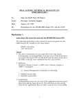
1
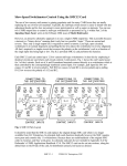
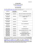
ST-193-091394
Sega Enterprises, Ltd.
NOTICE
When using this document, keep the following in mind:
1.
This document may, wholly or partially, be subject to change without notice.
2.
All rights are reserved: No one is permitted to reproduce or duplicate, in any
form, the whole or part of this document without SEGA’s permission.
3.
SEGA will not be held responsible for any damage to the user that may result
from accidents or any other reasons during operation of the user’s equipment,
or programs according to this document.
4.
Software, circuitry, and other examples described herein are meant merely to
indicate the characteristics and performance of SEGA’s products. SEGA
assumes no responsibility for any intellectual property claims or other
problems that may result from applications based on the examples describe
herein.
5.
No license is granted by implication or otherwise under any patents or other
rights of any third party or SEGA Enterprises, Ltd.
6.
This document is confidential. By accepting this document you acknowledge
that you are bounded by the terms set forth in the non-disclosure and
confidentiality agreement signed separately and/in the possession of SEGA. If
you have not signed such a non-disclosure agreement, please contact SEGA
immediately and return this document to SEGA.
(4/20/94 - 001)
ST-193-091394
Sega Enterprises, Ltd.
TM
SEGA SATURN
Sound Box
User’s Manual
Doc. # ST-193-091394
SEGA
© 1994 SEGA. All rights reserved.
ST-193-091394
Sega Enterprises, Ltd.
REFERENCES
In translating/creating this document, certain technical words and/or phrases were
interpreted with the assistance of the technical literature listed below.
1.
KenKyusha New Japanese-English Dictionary
1974 Edition
2.
Nelson's Japanese-English Character Dictionary
2nd revised version
3.
Microsoft Computer Dictionary
4.
Japanese-English Computer Terms Dictionary
Nichigai Associates
4th version
ST-193-091394
Sega Enterprises, Ltd.
History
Version 1:
(September 7, 1994)
• New version to be used with the Sound Box
ST-193-091394
Sega Enterprises, Ltd.
Preface
This manual describes the functions and uses of the SEGA SATURN Sound
Box made by SEGA Enterprises, Ltd. This manual has been adapted to the
SEGA SATURN Sound Box. The Sound Box product and product
specifications may change without notification. For more information about
specifications, inquiries can be made to the Support Centers listed in section
4.1
Terminology
Some of the terms used in this manual are explained below.
Sound Box
The abbreviated term for the SEGA SATURN sound box. It is the device or
mechanism for the SEGA SATURN Game Machine sound development. In
addition to having functions equal to those of the sound custom chip used in
the SEGA SATURN, sound development environment function has been
added to enable more efficient development.
Sound Development Environment
The environment for developing game sounds is loaded on to a sound board.
The functions below can be used in developing sounds.
•
•
•
•
SCSP function
Sound board control CPU MC68EC000
On-board emulator function
Sound development environment function
Sound Board
This board is for providing a sound development environment. A circuit for
realizing a sound development environment function is loaded on the board.
i
(RDJ, 9/27/94)
ST-193-091394
Sega Enterprises, Ltd.
(This page was blank in the original Japanese document.)
ii
(RDJ, 9/27/94)
ST-193-091394
Sega Enterprises, Ltd.
Table of Contents
Preface...................................................................................................................(i)
Terminology ...........................................................................................(i)
List of Figures...................................................................................................(iv)
List of Tables..................................................................................................... (iv)
Chapter 1 Appearance........................................................................................1
1.1 Appearance and Names of Each Part.............................................2
Front View .......................................................................................2
Rear View.........................................................................................3
Chapter 2 Unpacking and Installation (Setup).............................................5
2.1 Unpacking and Checking Accessories...........................................6
2.2 Sound Box Installation Method .....................................................7
Installation Environment.............................................................7
2.3 Power ON/OFF...................................................................................8
Connecting the AC Cable ..............................................................8
Power ON .........................................................................................8
Power OFF ........................................................................................8
Chapter 3 Description of Parts..........................................................................9
3.1 Panel Switches..................................................................................10
Reset Switch...................................................................................10
Sound Monitor Switch................................................................11
3.2 Sound Development Environment Relationship...................12
Connector Names.........................................................................12
SCSI ID Setting...............................................................................13
How to Set the SCSI ID ................................................................14
Chapter 4 Customer Support Service...........................................................15
4.1 Customer Support Service.............................................................16
Index .....................................................................................................................17
iii
(RDJ, 9/27/94)
ST-193-091394
Sega Enterprises, Ltd.
List of Figures
(Chapter 1 Appearance)
Figure 1.1 Sound Box Front View.......................................................2
Figure 1.2 Sound Box Rear View.........................................................3
(Chapter 2 Unpacking and Installation)
Figure 2.1 List of Package Contents .....................................................6
(Chapter 3 Description of Parts)
Figure 3.1 Panel Switch Names .........................................................10
Figure 3.2 Sound Connector Names.................................................12
Figure 3.3 Sound SCSI ID Set Switch Position................................13
Figure 3.4 Removing the Sound Box Cover...................................14
List of Tables
(Chapter 3 Description of Parts)
Table 3.1 Sound SCSI ID Settings.......................................................13
iv
(RDJ, 9/27/94)
ST-193-091394
Sega Enterprises, Ltd.
Chapter 1
Appearance
Chapter 1 Appearance
1.1 Appearance and Names of Each Part............2
Front View .............................................2
Rear View...............................................3
1
(RDJ, 9/27/94)
ST-193-091394
Sega Enterprises, Ltd.
1.1
Appearance and Names of Each Part
The appearance of the Sound Box is shown in Figures 1.1 and 1.2. More
information about each part can be found in chapter 3.
Front View
Figure 1.1 Sound Box Front View
<Name of Parts>
1) Sound Box
2) Panel Switch
3) Power Switch
2
(RDJ, 9/27/94)
ST-193-091394
Sega Enterprises, Ltd.
Rear View
Figure 1.2 Sound Box Rear View
Figure 1.2 shows the name of each part. Details of each part are given in
chapter 3.
1)
2)
AC inlet
Sound Development Environment Relational Connector
• MIDI Connector
• Audio Signal Output Connector
• Optical Digital Audio Signal Input Connector
• Sound Board Status Display LEDs
• Sound SCSI Connector
3
(RDJ, 9/27/94)
ST-193-091394
Sega Enterprises, Ltd.
(This page is blank in the original Japanese document.)
4
(RDJ, 9/27/94)
ST-193-091394
Sega Enterprises, Ltd.
Chapter 2
Unpacking and Installation (Setup)
Chapter 2 Unpacking and Installation (Setup)
2.1 Unpacking and Checking Accessories.................6
2.2 Sound Box Installation (Setup) Method.............7
Installation (Setup) Environment .................7
2.3 Power ON/OFF.........................................................8
Connecting the AC Cable .................................8
Power ON ............................................................8
Power OFF ...........................................................8
5
(RDJ, 9/27/94)
ST-193-091394
Sega Enterprises, Ltd.
2 . 1 Unpacking and Checking Accessories
First, remove all of the contents inside the box and check the list package
contents in Figure 2.1 to make sure that nothing is missing. Contact our
Customer Support Group if anything is damaged or missing. See chapter 4
"Customer Support Service" for more information.
(1) Sound Box
(2) AC Cable
(3) Sound Box
User's Manual
Figure 2.1 List of Package Contents
Item
1) Sound Box
2) AC Cable
3) SEGA SATURN Sound Box User's Manual (this manual)
Qnty
1
1
1
6
(RDJ, 9/27/94)
ST-193-091394
Sega Enterprises, Ltd.
2 . 2 Sound Box Installation (Setup) Method
Installation (Setup) Environment
Observe the following items when installing the Sound Box.
• Do not place in direct sunlight or near a heater.
• Do not install in an area of extremely high or low temperatures, and avoid
use in areas subject to violent vibration.
• To avoid external signal noise, do not plug the Sound Box into the same
AC outlet that is being used by other devices.
• Because the Sound Box generates a large amount of heat, a 5 cm space
around the Sound Box must be maintained.
• Never place anything on top of the Sound Box.
7
(RDJ, 9/27/94)
ST-193-091394
Sega Enterprises, Ltd.
2 . 3 Power On / OFF
Connecting the AC Cable
Observe the following items when connecting the AC cable.
1) Turn off the Sound Box power switch.
2) Plug the female side (end) of the AC cable into the Sound Box AC inlet.
3) Plug the AC grounded cable plug into an AC outlet.
Sound Box Input Specification are:
• AC85 V ~ 132 V
• 47 Hz ~ 63 Hz
• Maximum power consumption: 50 W
Power ON
1) Turn on the power by turning the Sound Box power switch to ON.
The power switch is a light which flashes whenever the power is
turned on.
2) This turns on the power of the host (such as a Mac) as well as peripheral
devices connected to the sound box.
Note:
If the light does not flash, turn off the power, recheck the connections of the AC cable
as well as other cables, then turn the power on again. If it still does not flash contact a
Support Centers.
Power OFF
Following the steps above in the reverse order shuts off the power.
8
(RDJ, 9/27/94)
ST-193-091394
Sega Enterprises, Ltd.
Chapter 3
Description of Parts
Chapter 3 Description of Parts
3.1 Panel Switches....................................................................10
Reset Switch..................................................................10
Sound Monitor Switch...............................................11
3.2 Sound Development Environment Relationship.....12
Connector Names........................................................12
SCSI ID Setting..............................................................13
How to Set the SCSI ID ...............................................14
9
(RDJ, 9/27/94)
ST-193-091394
Sega Enterprises, Ltd.
3 . 1 Panel Switches
The panel switches have the following functions.
• Resets the sound board
• Sound debug mode setting
Figure 3.1 Panel Switch Names
Reset Switch
This switch resets the entire sound board.
10
(RDJ, 9/27/94)
ST-193-091394
Sega Enterprises, Ltd.
Sound Monitor Switch
This switch determines whether the monitor program on the sound board is
used or not. The setting for using the monitor program is normally used.
Alive
This status allows the sound monitor program to be used. Pressing the reset
switch or turning on the power of the Sound Box with the sound monitor
switch set to Alive begins the operation of the sound board monitor program
and allows control of the sound board from the host machine (Macintosh, for
example) through the SCSI. This is the setting normally used.
Kill
This status prevents the sound monitor program from being used. Be aware
that in this status the Sound Box unit is not operational.
11
(RDJ, 9/27/94)
ST-193-091394
Sega Enterprises, Ltd.
3 . 2 Sound Development Environment Issues
Connector Names
Figure 3.2 explains names and simple functions of the sound development
relational connector (called sound connector below).
For connector positions, see rear view in chapter 1.
Figure 3.2
Sound Connector Names
1)
MIDI Connector
A dual system, each with an IN, OUT, and THRU connectors.
2)
OPT - IN
Enables the input of an optical digital audio signal.
3)
Audio - OUT
Has two channels: Rch and Lch.
An amplifier is required to boost the output.
4)
Sound Status Display LEDs
Various types of information are displayed via LEDs. See the sound
software manual for the display content.
5)
Sound SCSI
This is a SCSI connector. This is used when connecting with a SCSI
interface of the host machine such as a Macintosh. This SCSI supports
SCSI-I. Because this is a terminal process, make sure that it is the final
connector in the SCSI daisy chain cable.
12
(RDJ, 9/27/94)
ST-193-091394
Sega Enterprises, Ltd.
SCSI ID Setting
When a host machine (PC/AT, Mac, etc.) is connected to the SCSI, the SCSI ID
must be set. The SCSI ID can use the numbers 1 through 6. The ID is changed
by the switch on the sound board to a setting not used by another SCSI device,
such as a hard disk drive, already connected. The switch is set to an ID of 6 at
the time of shipment. To change switches, first remove the Sound Box cover,
then make the desired setting.
ID SETTING SWITCH
MIDI CONNECTOR
SCSI CONNECTOR
SOUND BOARD
ON
SW2
OFF
1 2 3 4 5 6 7 8
Figure 3.3 Sound SCSI ID set Switch Position
Table 3.1 Sound SCSI ID Settings
Switch No.
1
2
3
0
OFF
OFF
OFF
1
ON
OFF
OFF
2
OFF
ON
OFF
3
ON
ON
OFF
OFF
OFF
ON
5
ON
OFF
ON
6
OFF
ON
ON
7
ON
ON
ON
4
5
6
7
8
OFF
OFF
OFF
OFF
OFF
ID No.
4
Note: Settings at the time of shipment are shown within the double lines
13
(RDJ, 9/27/94)
ST-193-091394
Sega Enterprises, Ltd.
How to Set the SCSI ID
Follow the steps below when changing the SCSI ID. You do not need to
follow these steps if using ID=6 setting.
1. Remove the Sound Box cover.
• Make sure the power of all peripheral devices connected to the Sound
Box is off.
• Remove the Sound Box cover. There are five screws. See Figure 3.4.
BODY COVER
Figure 3.4
Removing the Sound Box Cover
2. Set the SCSI ID.
• Set the ID switch on the sound board according to Figure 3.4 and
Table 3.1.
3. Install the Sound Box cover.
• Cover the casing with the main cover and secure with five screws. See
Figure 3.4. Refer to "Remove the Sound Box cover."
14
(RDJ, 9/27/94)
ST-193-091394
Sega Enterprises, Ltd.
Chapter 4
Customer Support Service
Chapter 4 Customer Support Service
4.1 Customer Support Service Information.......................16
15
(RDJ, 9/27/94)
ST-193-091394
Sega Enterprises, Ltd.
4 . 1 Customer Support Service Information
Inquiries about the SEGA SATURN Sound Box can be made to the following
centers.
1)
SEGA Technical Inquiries
Company:
Department:
Address:
Fax:
Hours:
2)
SEGA Enterprises, Ltd.
Technical Support
275 Shoreline Dr./Redwood City/CA/94065
415-802-3963
10:00 am ~ 11:45 am, 12:45 pm ~ 7:00 pm
(Open Monday through Friday except on holidays.)
Sophia System Technical Inquiries
Company:
Department:
Address:
Tel:
Fax:
Hours:
Sophia Systems, Ltd.
Technical Support Center
6 - 2 Minami Kurogawa, Asabu-Ku
Kawasaki-Shi, Kanagawa-Ken, 215
044-989-7239 (direct)
044-989-7005
10:00 am ~ 12:00 pm, 1:00 pm ~ 5:00 pm
(Open Monday through Friday except on holidays.)
16
(RDJ, 9/27/94)
ST-193-091394
Sega Enterprises, Ltd.
INDEX
AC Inlet........................................................................................................................3
Accessories...................................................................................................................6
ALIVE.........................................................................................................................11
Amplifier...................................................................................................................12
Audio Signal Output Connector ............................................................................3
Audio-Out .................................................................................................................12
Customer Support Service.......................................................................................6
Daisy Chain Cable ....................................................................................................12
Front View ..................................................................................................................2
Host Machine (Host) ...........................................................................................8, 13
ID .................................................................................................................................13
Input Specifications...................................................................................................8
KILL.............................................................................................................................11
Lch...............................................................................................................................12
Mac................................................................................................................................8
Maximum Consumption Power............................................................................8
MC68E000..................................................................................................................... i
MIDI Connector..........................................................................................................3
Monitor Program.....................................................................................................11
On-board Emulator Function.................................................................................. i
OPT-IN .......................................................................................................................12
Optical Digital Audio Signal Input Connector....................................................3
Panel Switches............................................................................................................2
Power Switch ..............................................................................................................2
Rch ..............................................................................................................................12
Rear View....................................................................................................................3
Reset Switch..............................................................................................................10
SCSI.............................................................................................................................11
SCSI-I ..........................................................................................................................12
SCSP Function............................................................................................................ i
Sound Board ............................................................................................................... i
Sound Board Control CPU....................................................................................... i
Sound Board Status Display LED............................................................................3
Sound Box ................................................................................................................... i
Sound Custom Chip.................................................................................................. i
Sound Development Environment...................................................................... i
Sound Development Environment Relational Connector .............................3
Sound Development Environment Function.................................................... i
Sound Monitor Program........................................................................................11
Sound Monitor Switch...........................................................................................11
Sound SCSI Connector .............................................................................................3
Terminal Process......................................................................................................12
17