1
µ MOTOROLA
M68000
8-/16-/32-Bit
Microprocessors User’s Manual
Ninth Edition
Motorola reserves the right to make changes without further notice to any products herein. Motorola makes no warranty, representation or guarantee regarding
the suitability of its products for any particular purpose, nor does Motorola assume any liability arising out of the application or use of any product or circuit, and
specifically disclaims any and all liability, including without limitation consequential or incidental damages. "Typical" parameters can and do vary in different
applications. All operating parameters, including "Typicals" must be validated for each customer application by customer's technical experts. Motorola does not
convey any license under its patent rights nor the rights of others. Motorola products are not designed, intended, or authorized for use as components in systems
intended for surgical implant into the body, or other applications intended to support or sustain life, or for any other application in which the failure of the Motorola
product could create a situation where personal injury or death may occur. Should Buyer purchase or use Motorola products for any such unintended or
unauthorized application, Buyer shall indemnify and hold Motorola and its officers, employees, subsidiaries, affiliates, and distributors harmless against all claims,
costs, damages, and expenses, and reasonable attorney fees arising out of, directly or indirectly, any claim of personal injury or death associated with such
unintended or unauthorized use, even if such claim alleges that Motorola was negligent regarding the design or manufacture of the part. Motorola and µ are
registered trademarks of Motorola, Inc. Motorola, Inc. is an Equal Opportunity/Affirmative Action Employer.
©MOTOROLA INC., 1993
TABLE OF CONTENTS
Paragraph
Number
Title
Page
Number
Section 1
Overview
1.1
1.2
1.3
1.4
1.5
1.6
MC68000..................................................................................................... 1-1
MC68008..................................................................................................... 1-2
MC68010..................................................................................................... 1-2
MC68HC000................................................................................................ 1-2
MC68HC001................................................................................................ 1-3
MC68EC000 ................................................................................................ 1-3
Section 2
Introduction
2.1
2.1.1
2.1.2
2.1.3
2.2
2.3
2.3.1
2.3.2
2.4
2.5
Programmer's Model ................................................................................... 2-1
User's Programmer's Model .................................................................... 2-1
Supervisor Programmer's Model ............................................................. 2-2
Status Register ........................................................................................ 2-3
Data Types and Addressing Modes ............................................................ 2-3
Data Organization In Registers ................................................................... 2-5
Data Registers ......................................................................................... 2-5
Address Registers ................................................................................... 2-6
Data Organization In Memory ..................................................................... 2-6
Instruction Set Summary ............................................................................. 2-8
Section 3
Signal Description
3.1
3.2
3.3
3.4
3.5
3.6
3.7
3.8
3.9
3.10
3.11
MOTOROLA
Address Bus ................................................................................................ 3-3
Data Bus...................................................................................................... 3-4
Asynchronous Bus Control.......................................................................... 3-4
Bus Arbitration Control ................................................................................ 3-5
Interrupt Control .......................................................................................... 3-6
System Control............................................................................................ 3-7
M6800 Peripheral Control ........................................................................... 3-8
Processor Function Codes .......................................................................... 3-8
Clock ........................................................................................................... 3-9
Power Supply .............................................................................................. 3-9
Signal Summary ......................................................................................... 3-10
M68000 USER’S MANUAL
vii
TABLE OF CONTENTS (Continued)
Paragraph
Number
Title
Page
Number
Section 4
8-Bit Bus Operations
4.1
4.1.1
4.1.2
4.1.3
4.2
Data Transfer Operations............................................................................. 4-1
Read Operations ...................................................................................... 4-1
Write Cycle ............................................................................................... 4-3
Read-Modify-Write Cycle.......................................................................... 4-5
Other Bus Operations............................................................................... 4-8
Section 5
16-Bit Bus Operations
5.1
5.1.1
5.1.2
5.1.3
5.1.4
5.2
5.2.1
5.2.2
5.2.3
5.3
5.4
5.4.1
5.4.2
5.4.3
5.4.4
5.5
5.6
5.7
5.8
Data Transfer Operations............................................................................ 5-1
Read Operations ..................................................................................... 5-1
Write Cycle .............................................................................................. 5-4
Read-Modify-Write Cycle......................................................................... 5-7
CPU Space Cycle.................................................................................... 5-9
Bus Arbitration .......................................................................................... 5-11
Requesting The Bus .............................................................................. 5-14
Receiving The Bus Grant ...................................................................... 5-15
Acknowledgment of Mastership (3-Wire Arbitration Only)..................... 5-15
Bus Arbitration Control .............................................................................. 5-15
Bus Error and Halt Operation .................................................................... 5-23
Bus Error Operation .............................................................................. 5-24
Retrying The Bus Cycle......................................................................... 5-26
Halt Operation ....................................................................................... 5-27
Double Bus Fault ................................................................................... 5-28
Reset Operation ........................................................................................ 5-29
The Relationship of DTACK, BERR, and HALT ......................................... 5-30
Asynchronous Operation .......................................................................... 5-32
Synchronous Operation ............................................................................ 5-35
Section 6
Exception Processing
6.1
6.1.1
6.1.2
6.1.3
6.1.4
6.2
6.2.1
6.2.2
6.2.3
viii
Privilege Modes............................................................................................ 6-1
Supervisor Mode ...................................................................................... 6-2
User Mode ................................................................................................ 6-2
Privilege Mode Changes .......................................................................... 6-2
Reference Classification........................................................................... 6-3
Exception Processing................................................................................... 6-4
Exception Vectors .................................................................................... 6-4
Kinds Of Exceptions ................................................................................. 6-5
Multiple Exceptions................................................................................... 6-8
M68000 USER’S MANUAL
MOTOROLA
TABLE OF CONTENTS (Continued)
Paragraph
Number
Title
Page
Number
Section 6
Exception Processing
6.2.4
6.2.5
6.3
6.3.1
6.3.2
6.3.3
6.3.4
6.3.5
6.3.6
6.3.7
6.3.8
6.3.9
6.3.9.1
6.3.9.2
6.3.10
6.4
Exception Stack Frames.......................................................................... 6-9
Exception Processing Sequence ............................................................ 6-11
Processing of Specific Exceptions ............................................................. 6-11
Reset ...................................................................................................... 6-11
Interrupts ................................................................................................ 6-12
Uninitialized Interrupt .............................................................................. 6-13
Spurious Interrupt ................................................................................... 6-13
Instruction Traps ..................................................................................... 6-13
Illegal and Unimplemented Instructions .................................................. 6-14
Privilege Violations ................................................................................. 6-15
Tracing .................................................................................................... 6-15
Bus Errors ............................................................................................... 6-16
Bus Error ............................................................................................. 6-16
Bus Error (MC68010) .......................................................................... 6-17
Address Error ......................................................................................... 6-19
Return From Exception (MC68010) ........................................................... 6-20
Section 7
8-Bit Instruction Timing
7.1
7.2
7.3
7.4
7.5
7.6
7.7
7.8
7.9
7.10
7.11
7.12
MOTOROLA
Operand Effective Address Calculation Times............................................ 7-1
Move Instruction Execution Times .............................................................. 7-2
Standard Instruction Execution Times......................................................... 7-3
Immediate Instruction Execution Times ...................................................... 7-4
Single Operand Instruction Execution Times .............................................. 7-5
Shift/Rotate Instruction Execution Times .................................................... 7-6
Bit Manipulation Instruction Execution Times ............................................. 7-7
Conditional Instruction Execution Times ..................................................... 7-7
JMP, JSR, LEA, PEA, and MOVEM Instruction Execution Times............... 7-8
Multiprecision Instruction Execution Times ................................................. 7-8
Miscellaneous Instruction Execution Times ................................................ 7-9
Exception Processing Instruction Execution Times ................................... 7-10
M68000 USER’S MANUAL
ix
TABLE OF CONTENTS (Continued)
Paragraph
Number
Title
Page
Number
Section 8
16-Bit Instruction Timing
8.1
8.2
8.3
8.4
8.5
8.6
8.7
8.8
8.9
8.10
8.11
8.12
Operand Effective Address Calculation Times ........................................... 8-1
Move Instruction Execution Times .............................................................. 8-2
Standard Instruction Execution Times ........................................................ 8-3
Immediate Instruction Execution Times ...................................................... 8-4
Single Operand Instruction Execution Times .............................................. 8-5
Shift/Rotate Instruction Execution Times .................................................... 8-6
Bit Manipulation Instruction Execution Times ............................................. 8-7
Conditional Instruction Execution Times ..................................................... 8-7
JMP, JSR, LEA, PEA, and MOVEM Instruction Execution Times .............. 8-8
Multiprecision Instruction Execution Times ................................................. 8-8
Miscellaneous Instruction Execution Times ................................................ 8-9
Exception Processing Instruction Execution Times .................................. 8-10
Section 9
MC68010 Instruction Timing
9.1
9.2
9.3
9.4
9.5
9.6
9.7
9.8
9.9
9.10
9.11
9.12
Operand Effective Address Calculation Times ........................................... 9-2
Move Instruction Execution Times .............................................................. 9-2
Standard Instruction Execution Times ........................................................ 9-4
Immediate Instruction Execution Times ...................................................... 9-6
Single Operand Instruction Execution Times .............................................. 9-6
Shift/Rotate Instruction Execution Times .................................................... 9-8
Bit Manipulation Instruction Execution Times ............................................. 9-9
Conditional Instruction Execution Times ..................................................... 9-9
JMP, JSR, LEA, PEA, and MOVEM Instruction Execution Times ............ 9-10
Multiprecision Instruction Execution Times ............................................... 9-11
Miscellaneous Instruction Execution Times .............................................. 9-11
Exception Processing Instruction Execution Times .................................. 9-13
Section 10
Electrical and Thermal Characteristics
10.1
10.2
10.3
10.4
10.5
10.6
10.7
10.8
x
Maximum Ratings ..................................................................................... 10-1
Thermal Characteristics ............................................................................ 10-1
Power Considerations ............................................................................... 10-2
CMOS Considerations .............................................................................. 10-4
AC Electrical Specifications Definitions..................................................... 10-5
MC68000/68008/68010 DC Electrical Characteristics .............................. 10-7
DC Electrical Characteristics .................................................................... 10-8
AC Electrical Specifications—Clock Timing .............................................. 10-8
M68000 USER’S MANUAL
MOTOROLA
TABLE OF CONTENTS (Continued)
Paragraph
Number
Title
Page
Number
Section 10
Electrical and Thermal Characteristics
10.9
10.10
10.11
10.12
10.13
10.14
10.15
MC68008 AC Electrical Specifications—Clock Timing ............................. 10-9
AC Electrical Specifications—Read and Write Cycles ............................ 10-10
AC Electrical Specifications—MC68000 To M6800 Peripheral............... 10-15
AC Electrical Specifications—Bus Arbitration .........................................10-17
MC68EC000 DC Electrical Spec ifications.............................................. 10-23
MC68EC000 AC Electrical Specifications—Read and Write .................. 10-24
MC68EC000 AC Electrical Specifications—Bus Arbitration .................... 10-28
Section 11
Ordering Information and Mechanical Data
11.1
11.2
Pin Assignments........................................................................................ 11-1
Package Dimensions ................................................................................ 11-7
Appendix A
MC68010 Loop Mode Operation
Appendix B
M6800 Peripheral Interface
B.1
B.2
MOTOROLA
Data Transfer Operation............................................................................. B-1
Interrupt Interface Operation ...................................................................... B-4
M68000 USER’S MANUAL
xi
LIST OF ILLUSTRATIONS
Figure
Number
Title
Page
Number
2-1
2-2
2-3
2-4
2-5
2-6
2-7
User Programmer's Model ................................................................................... 2-2
Supervisor Programmer's Model Supplement ..................................................... 2-2
Supervisor Programmer's Model Supplement (MC68010) .................................. 2-3
Status Register .................................................................................................... 2-3
Word Organization In Memory ............................................................................. 2-6
Data Organization In Memory .............................................................................. 2-7
Memory Data Organization (MC68008) ............................................................... 2-3
3-1
3-2
3-3
3-4
3-5
Input and Output Signals (MC68000, MC68HC000, MC68010) .......................... 3-1
Input and Output Signals ( MC68HC001) ............................................................ 3-2
Input and Output Signals (MC68EC000) ............................................................. 3-2
Input and Output Signals (MC68008 48-Pin Version) .......................................... 3-3
Input and Output Signals (MC68008 52-Pin Version) .......................................... 3-3
4-1
4-2
4-3
4-4
4-5
4-6
Byte Read-Cycle Flowchart.................................................................................. 4-2
Read and Write-Cycle Timing Diagram................................................................ 4-2
Byte Write-Cycle Flowchart .................................................................................. 4-4
Write-Cycle Timing Diagram ................................................................................ 4-4
Read-Modify-Write Cycle Flowchart .................................................................... 4-6
Read-Modify-Write Cycle Timing Diagram........................................................... 4-7
5-1
5-2
5-3
5-4
5-5
5-6
5-7
5-8
5-9
5-10
5-11
5-12
5-13
Word Read-Cycle Flowchart ................................................................................ 5-2
Byte Read-Cycle Flowchart.................................................................................. 5-2
Read and Write-Cycle Timing Diagram................................................................ 5-3
Word and Byte Read-Cycle Timing Diagram ....................................................... 5-3
Word Write-Cycle Flowchart ................................................................................ 5-5
Byte Write-Cycle Flowchart .................................................................................. 5-5
Word and Byte Write-Cycle Timing Diagram ....................................................... 5-6
Read-Modify-Write Cycle Flowchart .................................................................... 5-7
Read-Modify-Write Cycle Timing Diagram........................................................... 5-8
CPU Space Address Encoding ............................................................................ 5-9
Interrupt Acknowledge Cycle Timing Diagram ................................................... 5-10
Breakpoint Acknowledge Cycle Timing Diagram ............................................... 5-11
3-Wire Bus Arbitration Flowchart
(NA to 48-Pin MC68008 and MC68EC000 ........................................................ 5-12
2-Wire Bus Arbitration Cycle Flowchart ............................................................. 5-13
5-14
xii
M68000 USER’S MANUAL
MOTOROLA
LIST OF ILLUSTRATIONS (Continued)
Figure
Number
5-15
Title
Page
Number
5-16
5-17
5-18
5-19
5-20
5-21
5-22
5-23
5-24
5-25
5-26
5-27
5-28
5-29
5-30
5-31
5-32
5-33
5-34
5-35
5-36
5-37
3-Wire Bus Arbitration Timing Diagram
(NA to 48-Pin MC68008 and MC68EC000 ........................................................ 5-13
2-Wire Bus Arbitration Timing Diagram.............................................................. 5-14
External Asynchronous Signal Synchronization ................................................. 5-16
Bus Arbitration Unit State Diagrams................................................................... 5-17
3-Wire Bus Arbitration Timing Diagram—Processor Active ...............................5-18
3-Wire Bus Arbitration Timing Diagram—Bus Active ......................................... 5-19
3-Wire Bus Arbitration Timing Diagram—Special Case ................................ ..... 5-20
2-Wire Bus Arbitration Timing Diagram—Processor Active ...............................5-21
2-Wire Bus Arbitration Timing Diagram—Bus Active ......................................... 5-22
2-Wire Bus Arbitration Timing Diagram—Special Case ................................ ..... 5-23
Bus Error Timing Diagram ..................................................................................5-24
Delayed Bus Error Timing Diagram (MC68010)................................................. 5-25
Retry Bus Cycle Timing Diagram ....................................................................... 5-26
Delayed Retry Bus Cycle Timing Diagram ......................................................... 5-27
Halt Operation Timing Diagram.......................................................................... 5-28
Reset Operation Timing Diagram....................................................................... 5-29
Fully Asynchronous Read Cycle ........................................................................ 5-32
Fully Asynchronous Write Cycle......................................................................... 5-33
Pseudo-Asynchronous Read Cycle ................................................................... 5-34
Pseudo-Asynchronous Write Cycle.................................................................... 5-35
Synchronous Read Cycle................................................................................... 5-37
Synchronous Write Cycle ................................................................................... 5-38
Input Synchronizers ........................................................................................... 5-38
6-1
6-2
6-3
6-4
6-5
6-6
6-7
6-8
6-9
Exception Vector Format...................................................................................... 6-4
Peripheral Vector Number Format ....................................................................... 6-5
Address Translated from 8-Bit Vector Number ................................................... 6-5
Exception Vector Address Calculation (MC68010) .............................................. 6-5
Group 1 and 2 Exception Stack Frame .............................................................. 6-10
MC68010 Stack Frame ...................................................................................... 6-10
Supervisor Stack Order for Bus or Address Error Exception ............................. 6-17
Exception Stack Order (Bus and Address Error) ............................................... 6-18
Special Status Word Format .............................................................................. 6-19
10-1
10-2
10-3
10-4
10-5
10-6
MC68000 Power Dissipation (P D) vs Ambient Temperature (TA) ..................... 10-3
Drive Levels and Test Points for AC Specifications ........................................... 10-6
Clock Input Timing Diagram ............................................................................... 10-9
Read Cycle Timing Diagram ............................................................................ 10-13
Write Cycle Timing Diagram............................................................................. 10-14
MC68000 to M6800 Peripheral Timing Diagram (Best Case) .......................... 10-16
MOTOROLA
M68000 USER’S MANUAL
xiii
LIST OF ILLUSTRATIONS (Concluded)
Figure
Number
Title
Page
Number
10-7
10-8
10-9
10-10
10-11
10-12
10-13
10-14
Bus Arbitration Timing...................................................................................... 10-18
Bus Arbitration Timing...................................................................................... 10-19
Bus Arbitration Timing—Idle Bus Case ............................................................ 10-20
Bus Arbitration Timing—Active Bus Case........................................................ 10-21
Bus Arbitration Timing—Multiple Bus Request ................................................ 10-22
MC68EC000 Read Cycle Timing Diagram ...................................................... 10-26
MC68EC000 Write Cycle Timing Diagram....................................................... 10-27
MC68EC000 Bus Arbitration Timing Diagram ................................................. 10-29
11-1
11-2
11-3
11-4
11-5
11-6
11-7
11-8
11-9
11-10
11-11
11-12
11-13
11-14
11-15
64-Pin Dual In Line ............................................................................................ 11-2
68-Lead Pin Grid Array ...................................................................................... 11-3
68-Lead Quad Pack ........................................................................................... 11-4
52-Lead Quad Pack ........................................................................................... 11-5
48-Pin Dual In Line ............................................................................................ 11-6
64-Lead Quad Flat Pack .................................................................................... 11-7
Case 740-03—L Suffix ....................................................................................... 11-8
Case 767-02—P Suffix ...................................................................................... 11-9
Case 746-01—LC Suffix .................................................................................. 11-10
Case — Suffix ...................................................................................................... 11Case 765A-05—RC Suffix ............................................................................... 11-12
Case 778-02—FN Suffix .................................................................................. 11-13
Case 779-02—FN Suffix .................................................................................. 11-14
Case 847-01—FC Suffix .................................................................................. 11-15
Case 840B-01—FU Suffix................................................................................ 11-16
A-1
DBcc Loop Mode Program Example................................................................... A-1
B-1
B-2
B-3
B-4
B-5
B-6
M6800 Data Transfer Flowchart .........................................................................
Example External VMA Circuit ............................................................................
External VMA Timing ..........................................................................................
M6800 Peripheral Timing—Best Case................................................................
M6800 Peripheral Timing—Worst Case .............................................................
Autovector Operation Timing Diagram................................................................
xiv
M68000 USER’S MANUAL
B-1
B-2
B-2
B-3
B-3
B-5
MOTOROLA
LIST OF TABLES
Table
Number
Title
Page
Number
2-1
Data Addressing Modes ....................................................................................... 2-4
2-2
Instruction Set Summary .................................................................................... 2-11
3-1
3-2
3-3
3-4
Data Strobe Control of Data Bus.......................................................................... 3-5
Data Strobe Control of Data Bus (MC68008)....................................................... 3-5
Function Code Output .......................................................................................... 3-9
Signal Summary ................................................................................................. 3-10
5-1
DTACK, BERR, and HALT Assertion Results ..................................................... 5-31
6-1
6-2
6-3
6-4
Reference Classification....................................................................................... 6-3
Exception Vector Assignment .............................................................................. 6-7
Exception Grouping and Priority........................................................................... 6-9
MC68010 Format Code...................................................................................... 6-11
7-1
7-2
7-3
7-4
7-5
7-6
7-7
7-8
7-9
7-10
7-11
7-12
7-13
7-14
7-15
Effective Address Calculation Times.................................................................... 7-2
Move Byte Instruction Execution Times ............................................................... 7-2
Move Word Instruction Execution Times.............................................................. 7-3
Move Long Instruction Execution Times .............................................................. 7-3
Standard Instruction Execution Times.................................................................. 7-4
Immediate Instruction Execution Times ............................................................... 7-5
Single Operand Instruction Execution Times ....................................................... 7-6
Shift/Rotate Instruction Execution Times ............................................................. 7-6
Bit Manipulation Instruction Execution Times ...................................................... 7-7
Conditional Instruction Execution Times .............................................................. 7-7
JMP, JSR, LEA, PEA, and MOVEM Instruction Execution Times........................ 7-8
Multiprecision Instruction Execution Times .......................................................... 7-9
Miscellaneous Instruction Execution Times ....................................................... 7-10
Move Peripheral Instruction Execution Times .................................................... 7-10
Exception Processing Instruction Execution Times ........................................... 7-11
8-1
8-2
8-3
8-4
Effective Address Calculation Times.................................................................... 8-2
Move Byte Instruction Execution Times ............................................................... 8-2
Move Word Instruction Execution Times.............................................................. 8-3
Move Long Instruction Execution Times .............................................................. 8-3
MOTOROLA
M68000 USER’S MANUAL
xv
LIST OF TABLES (Concluded)
Table
Number
Title
Page
Number
8-5
8-6
8-7
8-8
8-9
8-10
8-11
8-12
8-13
8-14
8-15
Standard Instruction Execution Times ................................................................. 8-4
Immediate Instruction Execution Times ............................................................... 8-5
Single Operand Instruction Execution Times ....................................................... 8-6
Shift/Rotate Instruction Execution Times ............................................................. 8-6
Bit Manipulation Instruction Execution Times ...................................................... 8-7
Conditional Instruction Execution Times .............................................................. 8-7
JMP, JSR, LEA, PEA, and MOVEM Instruction Execution Times ....................... 8-8
Multiprecision Instruction Execution Times .......................................................... 8-9
Miscellaneous Instruction Execution Times ....................................................... 8-10
Move Peripheral Instruction Execution Times.................................................... 8-10
Exception Processing Instruction Execution Times ........................................... 8-11
9-1
9-2
9-3
9-4
9-5
9-6
9-7
9-8
9-9
9-10
9-11
9-12
9-13
9-14
9-15
9-16
9-17
9-18
9-19
Effective Address Calculation Times ................................................................... 9-2
Move Byte and Word Instruction Execution Times .............................................. 9-3
Move Byte and Word Instruction Loop Mode Execution Times ........................... 9-3
Move Long Instruction Execution Times .............................................................. 9-4
Move Long Instruction Loop Mode Execution Times ........................................... 9-4
Standard Instruction Execution Times ................................................................. 9-5
Standard Instruction Loop Mode Execution Times .............................................. 9-5
Immediate Instruction Execution Times ............................................................... 9-6
Single Operand Instruction Execution Times ....................................................... 9-7
Clear Instruction Execution Times ....................................................................... 9-7
Single Operand Instruction Loop Mode Execution Times .................................... 9-8
Shift/Rotate Instruction Execution Times ............................................................. 9-8
Shift/Rotate Instruction Loop Mode Execution Times .......................................... 9-9
Bit Manipulation Instruction Execution Times ...................................................... 9-9
Conditional Instruction Execution Times ............................................................ 9-10
JMP, JSR, LEA, PEA, and MOVEM Instruction Execution Times ..................... 9-10
Multiprecision Instruction Execution Times ........................................................ 9-11
Miscellaneous Instruction Execution Times ....................................................... 9-12
Exception Processing Instruction Execution Times ........................................... 9-13
10-1
10-2
Power Dissipation and Junction Temperature vs Temperature
(θJC = θJA) ........................................................................................................ 10-4
Power Dissipation and Junction Temperature vs Temperature
(θJC = θJC ) ........................................................................................................ 10-4
A-1
MC68010 Loop Mode Instructions ...................................................................... A-3
xvi
M68000 USER’S MANUAL
MOTOROLA
SECTION 1
OVERVIEW
This manual includes hardware details and programming information for the MC68000,
the MC68HC000, the MC68HC001, the MC68008, the MC68010, and the MC68EC000.
For ease of reading, the name M68000 MPUs will be used when referring to all
processors. Refer to M68000PM/AD, M68000 Programmer's Reference Manual, for
detailed information on the MC68000 instruction set.
The six microprocessors are very similar. They all contain the following features
• 16 32-Bit Data and Address Registers
• 16-Mbyte Direct Addressing Range
• Program Counter
• 6 Powerful Instruction Types
• Operations on Five Main Data Types
• Memory-Mapped Input/Output (I/O)
• 14 Addressing Modes
The following processors contain additional features:
• MC68010
—Virtual Memory/Machine Support
—High-Performance Looping Instructions
• MC68HC001/MC68EC000
—Statically Selectable 8- or 16-Bit Data Bus
• MC68HC000/MC68EC000/MC68HC001
—Low-Power
All the processors are basically the same with the exception of the MC68008. The
MC68008 differs from the others in that the data bus size is eight bits, and the address
range is smaller. The MC68010 has a few additional instructions and instructions that
operate differently than the corresponding instructions of the other devices.
MOTOROLA
M68000 8-/16-/32-BIT MICROPROCESSORS USER’S MANUAL
1-1
1.1
MC68000
The MC68000 is the first implementation of the M68000 16/-32 bit microprocessor
architecture. The MC68000 has a 16-bit data bus and 24-bit address bus while the full
architecture provides for 32-bit address and data buses. It is completely code-compatible
with the MC68008 8-bit data bus implementation of the M68000 and is upward code
compatible with the MC68010 virtual extensions and the MC68020 32-bit implementation
of the architecture. Any user-mode programs using the MC68000 instruction set will run
unchanged on the MC68008, MC68010, MC68020, MC68030, and MC68040. This is
possible because the user programming model is identical for all processors and the
instruction sets are proper subsets of the complete architecture.
1.2
MC68008
The MC68008 is a member of the M68000 family of advanced microprocessors. This
device allows the design of cost-effective systems using 8-bit data buses while providing
the benefits of a 32-bit microprocessor architecture. The performance of the MC68008 is
greater than any 8-bit microprocessor and superior to several 16-bit microprocessors.
The MC68008 is available as a 48-pin dual-in-line package (plastic or ceramic) and 52-pin
plastic leaded chip carrier. The additional four pins of the 52-pin package allow for
additional signals: A20, A21, BGACK, and IPL2. The 48-pin version supports a 20-bit
address that provides a 1-Mbyte address space; the 52-pin version supports a 22-bit
address that extends the address space to 4 Mbytes. The 48-pin MC68008 contains a
simple two-wire arbitration circuit; the 52-pin MC68008 contains a full three-wire MC68000
bus arbitration control. Both versions are designed to work with daisy-chained networks,
priority encoded networks, or a combination of these techniques.
A system implementation based on an 8-bit data bus reduces system cost in comparison
to 16-bit systems due to a more effective use of components and byte-wide memories and
peripherals. In addition, the nonmultiplexed address and data buses eliminate the need for
external demultiplexers, further simplifying the system.
The large nonsegmented linear address space of the MC68008 allows large modular
programs to be developed and executed efficiently. A large linear address space allows
program segment sizes to be determined by the application rather than forcing the
designer to adopt an arbitrary segment size without regard to the application's individual
requirements.
1.3
MC68010
The MC68010 utilizes VLSI technology and is a fully implemented 16-bit microprocessor
with 32-bit registers, a rich basic instruction set, and versatile addressing modes. The
vector base register (VBR) allows the vector table to be dynamically relocated
1-2
M68000 8-/16-/32-BIT MICROPROCESSORS USER’S MANUAL
MOTOROLA
1.4
MC68HC000
The primary benefit of the MC68HC000 is reduced power consumption. The device
dissipates an order of magnitude less power than the HMOS MC68000.
The MC68HC000 is an implementation of the M68000 16/-32 bit microprocessor
architecture. The MC68HC000 has a 16-bit data bus implementation of the MC68000 and
is upward code-compatible with the MC68010 virtual extensions and the MC68020 32-bit
implementation of the architecture.
1.5
MC68HC001
The MC68HC001 provides a functional extension to the MC68HC000 HCMOS 16-/32-bit
microprocessor with the addition of statically selectable 8- or 16-bit data bus operation.
The MC68HC001 is object-code compatible with the MC68HC000, and code written for
the MC68HC001 can be migrated without modification to any member of the M68000
Family.
1.6
MC68EC000
The MC68EC000 is an economical high-performance embedded controller designed to
suit the needs of the cost-sensitive embedded controller market. The HCMOS
MC68EC000 has an internal 32-bit architecture that is supported by a statically selectable
8- or 16-bit data bus. This architecture provides a fast and efficient processing device that
can satisfy the requirements of sophisticated applications based on high-level languages.
The MC68EC000 is object-code compatible with the MC68000, and code written for the
MC68EC000 can be migrated without modification to any member of the M68000 Family.
The MC68EC000 brings the performance level of the M68000 Family to cost levels
previously associated with 8-bit microprocessors. The MC68EC000 benefits from the rich
M68000 instruction set and its related high code density with low memory bandwidth
requirements.
MOTOROLA
M68000 8-/16-/32-BIT MICROPROCESSORS USER’S MANUAL
1-3
1-4
M68000 8-/16-/32-BIT MICROPROCESSORS USER’S MANUAL
MOTOROLA
SECTION 2
INTRODUCTION
The section provide a brief introduction to the M68000 microprocessors (MPUs).
Detailed information on the programming model, data types, addressing modes, data
organization and instruction set can be found in M68000PM/AD, M68000 Programmer's
Reference Manual. All the processors are identical from the programmer's viewpoint,
except that the MC68000 can directly access 16 Mbytes (24-bit address) and the
MC68008 can directly access 1 Mbyte (20-bit address on 48-pin version or 22-bit
address on 52-pin version). The MC68010, which also uses a 24-bit address, has much
in common with the other devices; however, it supports additional instructions and
registers and provides full virtual machine/memory capability. Unless noted, all
information pertains to all the M68000 MPUs.
2.1
PROGRAMMER'S MODEL
All the microprocessors executes instructions in one of two modes—user mode or
supervisor mode. The user mode provides the execution environment for the majority of
application programs. The supervisor mode, which allows some additional instructions
and privileges, is used by the operating system and other system software.
2.1.1 User' Programmer's Model
The user programmer's model (see Figure 2-1) is common to all M68000 MPUs. The
user programmer's model, contains 16, 32-bit, general-purpose registers (D0–D7, A0–
A7), a 32-bit program counter, and an 8-bit condition code register. The first eight
registers (D0–D7) are used as data registers for byte (8-bit), word (16-bit), and long-word
(32-bit) operations. The second set of seven registers (A0–A6) and the user stack pointer
(USP) can be used as software stack pointers and base address registers. In addition,
the address registers can be used for word and long-word operations. All of the 16
registers can be used as index registers.
MOTOROLA
M68000 8-/16-/32-BIT MICROPROCESSOR USER’S MANUAL
2-1
31
16 15
8 7
0
D0
D1
D2
D3
EIGHT
DATA
REGISTERS
D4
D5
D6
D7
31
16 15
0
A0
A1
A2
SEVEN
ADDRESS
REGISTERS
A3
A4
A5
A6
A7
USER STACK
(USP) POINTER
31
0
7
PC
PROGRAM
COUNTER
CCR
STATUS
REGISTER
0
Figure 2-1. User Programmer's Model
(MC68000/MC68HC000/MC68008/MC68010)
2.1.2 Supervisor Programmer's Model
The supervisor programmer's model consists of supplementary registers used in the
supervisor mode. The M68000 MPUs contain identical supervisor mode register
resources, which are shown in Figure 2-2, including the status register (high-order byte)
and the supervisor stack pointer (SSP/A7').
31
16 15
0
A7'
SUPERVISOR STACK
(SSP) POINTER
15
8 7
0
CCR
SR
STATUS REGISTER
Figure 2-2. Supervisor Programmer's Model Supplement
The supervisor programmer's model supplement of the MC68010 is shown in Figure 23. In addition to the supervisor stack pointer and status register, it includes the vector
base register (VRB) and the alternate function code registers (AFC).The VBR is used to
determine the location of the exception vector table in memory to support multiple vector
2-2
M68000 8-/16-/32-BIT MICROPROCESSOR USER’S MANUAL
MOTOROLA
tables. The SFC and DFC registers allow the supervisor to access user data space or
emulate CPU space cycles.
31
16 15
15
0
8 7
A7'
(SSP)
SUPERVISOR STACK
POINTER
SR
STATUS REGISTER
VBR
VECTOR BASE REGISTER
SFC
ALTERNATE FUNCTION
CODE REGISTERS
0
CCR
31
0
2
0
DFC
Figure 2-3. Supervisor Programmer's Model Supplement
(MC68010)
2.1.3 Status Register
The status register (SR),contains the interrupt mask (eight levels available) and the
following condition codes: overflow (V), zero (Z), negative (N), carry (C), and extend (X).
Additional status bits indicate that the processor is in the trace (T) mode and/or in the
supervisor (S) state (see Figure 2-4). Bits 5, 6, 7, 11, 12, and 14 are undefined and
reserved for future expansion
SYSTEM BYTE
15
13
T
S
USER BYTE
10
8
I2 I1 I0
4
X
0
N Z V
C
TRACE MODE
EXTEND
NEGATIVE
ZERO
OVERFLOW
CARRY
SUPERVISOR
STATE
INTERRUPT
MASK
CONDITION
CODES
Figure 2-4. Status Register
2.2
DATA TYPES AND ADDRESSING MODES
The five basic data types supported are as follows:
1. Bits
2. Binary-Coded-Decimal (BCD) Digits (4 Bits)
3. Bytes (8 Bits)
4. Words (16 Bits)
5. Long Words (32 Bits)
MOTOROLA
M68000 8-/16-/32-BIT MICROPROCESSOR USER’S MANUAL
2-3
In addition, operations on other data types, such as memory addresses, status word
data, etc., are provided in the instruction set.
The 14 flexible addressing modes, shown in Table 2-1, include six basic types:
1. Register Direct
2. Register Indirect
3. Absolute
4. Immediate
5. Program Counter Relative
6. Implied
The register indirect addressing modes provide postincrementing, predecrementing,
offsetting, and indexing capabilities. The program counter relative mode also supports
indexing and offsetting. For detail information on addressing modes refer to
M68000PM/AD, M68000 Programmer Reference Manual.
2-4
M68000 8-/16-/32-BIT MICROPROCESSOR USER’S MANUAL
MOTOROLA
Table 2-1. Data Addressing Modes
Mode
Syntax
Register Direct Addressing
Data Register Direct
Address Register Direct
EA=Dn
EA=An
Dn
An
Absolute Data Addressing
Absolute Short
Absolute Long
EA = (Next Word)
EA = (Next Two Words)
(xxx).W
(xxx).L
EA = (PC)+d16
EA = (PC)+d8
(d16,PC)
(d8,PC,Xn)
EA = (An)
EA = (An), An ← An+N
An ¯ An–N, EA=(An)
EA = (An)+d16
EA = (An)+(Xn)+d8
(An)
(An)+
-(An)
(d16,An)
(d8,An,Xn)
DATA = Next Word(s)
Inherent Data
#<data>
EA = SR, USP, SSP, PC,
VBR, SFC, DFC
SR,USP,SSP,PC,
VBR, SFC,DFC
Program Counter Relative
Addressing
Relative with Offset
Relative with Index and Offset
Register Indirect Addressing
Register Indirect
Postincrement Register Indirect
Predecrement Register Indirect
Register Indirect with Offset
Indexed Register Indirect with Offset
Immediate Data Addressing
Immediate
Quick Immediate
Implied Addressing 1
Implied Register
NOTES:
2.3
Generation
1. The VBR, SFC, and DFC apply to the MC68010 only
EA = Effective Address
Dn = Data Register
An = Address Register
()
= Contents of
PC = Program Counter
d8
= 8-Bit Offset (Displacement)
d16 = 16-Bit Offset (Displacement)
N
= 1 for byte, 2 for word, and 4 for long word. If An is the stack pointer and
the operand size is byte, N = 2 to keep the stack pointer on a word boundary.
¯
= Replaces
Xn = Address or Data Register used as Index Register
SR = Status Register
USP = User Stack Pointer
SSP = Supervisor Stack Pointer
CP = Program Counter
VBR = Vector Base Register
DATA ORGANIZATION IN REGISTERS
The eight data registers support data operands of 1, 8, 16, or 32 bits. The seven address
registers and the active stack pointer support address operands of 32 bits.
2.3.1 Data Registers
Each data register is 32 bits wide. Byte operands occupy the low-order 8 bits, word
operands the low-order 16 bits, and long-word operands, the entire 32 bits. The least
significant bit is addressed as bit zero; the most significant bit is addressed as bit 31.
MOTOROLA
M68000 8-/16-/32-BIT MICROPROCESSOR USER’S MANUAL
2-5
When a data register is used as either a source or a destination operand, only the
appropriate low-order portion is changed; the remaining high-order portion is neither
used nor changed.
2.3.2 Address Registers
Each address register (and the stack pointer) is 32 bits wide and holds a full, 32-bit
address. Address registers do not support byte-sized operands. Therefore, when an
address register is used as a source operand, either the low-order word or the entire
long-word operand is used, depending upon the operation size. When an address
register is used as the destination operand, the entire register is affected, regardless of
the operation size. If the operation size is word, operands are sign-extended to 32 bits
before the operation is performed.
2.4
DATA ORGANIZATION IN MEMORY
Bytes are individually addressable. As shown in Figure 2-5, the high-order byte of a
word has the same address as the word. The low-order byte has an odd address, one
count higher. Instructions and multibyte data are accessed only on word (even byte)
boundaries. If a long-word operand is located at address n (n even), then the second
word of that operand is located at address n+2.
15
14
13
12
11
BYTE 000000
$000002
BYTE 000002
$FFFFFE
10
9
8
7
6
5
4
3
2
1
0
WORD 0
ADDRESS
$000000
BYTE 000001
WORD 1
BYTE 000003
WORD 7FFFFF
BYTE FFFFFE
BYTE FFFFFE
Figure 2-5. Word Organization in Memory
The data types supported by the M68000 MPUs are bit data, integer data of 8, 16, and
32 bits, 32-bit addresses, and binary-coded-decimal data. Each data type is stored in
memory as shown in Figure 2-6. The numbers indicate the order of accessing the data
from the processor. For the MC68008 with its 8-bit bus, the appearance of data in
memory is identical to the all the M68000 MPUs. The organization of data in the memory
of the MC68008 is shown in Figure 2-7.
2-6
M68000 8-/16-/32-BIT MICROPROCESSOR USER’S MANUAL
MOTOROLA
7
15
14
13
12
11
6
BIT DATA
1 BYTE = 8 BITS
5
4
3
2
1
0
10
INTEGER DATA
1 BYTE = 8 BITS
9
8
7
6
5
4
BYTE 0
MSB
14
13
12
11
2
1
0
2
1
0
BYTE 1
LSB
BYTE 2
15
3
BYTE 3
10
1 WORD = 16 BITS
9
8
7
6
5
4
3
WORD 0
MSB
LSB
WORD 1
WORD 2
EVEN BYTE
7
ODD BYTE
6
5
4
3
2
15
14
MSB
13
12
11
10
1
0
7
6
1 LONG WORD = 32 BITS
9
8
7
6
5
4
3
2
1
0
5
4
3
2
1
0
HIGH ORDER
LONG WORD 0
LOW ORDER
LSB
LONG WORD 1
LONG WORD 2
15
14
MSB
13
12
11
10
ADDRESSES
1 ADDRESS = 32 BITS
9
8
7
6
5
4
3
2
1
0
HIGH ORDER
ADDRESS 0
LOW ORDER
LSB
ADDRESS 1
ADDRESS 2
MSB = MOST SIGNIFICANT BIT
LSB = LEAST SIGNIFICANT BIT
15
14
MSD
13
12
DECIMAL DATA
2 BINARY-CODED-DECIMAL DIGITS = 1 BYTE
11
10
9
8
7
6
5
4
BCD 0
BCD 1
BCD 4
BCD 5
LSD
3
2
BCD 2
BCD 3
BCD 6
BCD 7
1
0
MSD = MOST SIGNIFICANT DIGIT
LSD = LEAST SIGNIFICANT DIGIT
Figure 2-6. Data Organization in Memory
MOTOROLA
M68000 8-/16-/32-BIT MICROPROCESSOR USER’S MANUAL
2-7
7
6
BIT DATA 1 BYTE = 8 BITS
5
4
3
2
1
0
7
6
INTEGER DATA 1 BYTE = 8 BITS
5
4
3
2
1
0
BYTE 0
LOWER ADDRESSES
BYTE 1
BYTE 2
HIGHER ADDRESSES
BYTE 3
1 WORD = 2 BYTES = 16 BITS
BYTE 0 (MS BYTE)
LOWER ADDRESSES
WORD 0
BYTE 1 (LS BYTE)
BYTE 0 (MS BYTE)
WORD 1
BYTE 1 (LS BYTE)
HIGHER ADDRESSES
1 LONG WORD = 2 WORDS = 4 BYTES = 32 BITS
BYTE 0
HIGH-ORDER
WORD
BYTE 1
LOWER ADDRESSES
LONG WORD 0
BYTE 2
LOW-ORDER
WORD
BYTE 3
BYTE 0
HIGH-ORDER
WORD
BYTE 1
LONG WORD 1
BYTE 2
BYTE 3
LOW-ORDER
WORD
HIGHER ADDRESSES
Figure 2-7. Memory Data Organization of the MC68008
2.5
INSTRUCTION SET SUMMARY
Table 2-2 provides an alphabetized listing of the M68000 instruction set listed by
opcode, operation, and syntax. In the syntax descriptions, the left operand is the source
operand, and the right operand is the destination operand. The following list contains the
notations used in Table 2-2.
2-8
M68000 8-/16-/32-BIT MICROPROCESSOR USER’S MANUAL
MOTOROLA
Notation for operands:
PC —
SR —
V—
Immediate Data —
Source —
Destination —
Vector —
+inf —
–inf —
<fmt> —
Program counter
Status register
Overflow condition code
Immediate data from the instruction
Source contents
Destination contents
Location of exception vector
Positive infinity
Negative infinity
Operand data format: byte (B), word (W), long (L), single
(S), double (D), extended (X), or packed (P).
FPm — One of eight floating-point data registers (always
specifies the source register)
FPn — One of eight floating-point data registers (always
specifies the destination register)
Notation for subfields and qualifiers:
<bit> of <operand> — Selects a single bit of the operand
<ea>{offset:width} — Selects a bit field
(<operand>) — The contents of the referenced location
<operand>10 — The operand is binary-coded decimal, operations are
performed in decimal
(<address register>) — The register indirect operator
–(<address register>) — Indicates that the operand register points to the memory
(<address register>)+ — Location of the instruction operand—the optional mode
qualifiers are –, +, (d), and (d, ix)
#xxx or #<data> — Immediate data that follows the instruction word(s)
Notations for operations that have two operands, written <operand> <op> <operand>,
where <op> is one of the following:
→
↔
+
–
—
—
—
—
×—
÷—
<—
>—
V—
⊕—
Λ—
MOTOROLA
The source operand is moved to the destination operand
The two operands are exchanged
The operands are added
The destination operand is subtracted from the source
operand
The operands are multiplied
The source operand is divided by the destination
operand
Relational test, true if source operand is less than
destination operand
Relational test, true if source operand is greater than
destination operand
Logical OR
Logical exclusive OR
Logical AND
M68000 8-/16-/32-BIT MICROPROCESSOR USER’S MANUAL
2-9
shifted by, rotated by — The source operand is shifted or rotated by the number of
positions specified by the second operand
Notation for single-operand operations:
~<operand> — The operand is logically complemented
<operand>sign-extended — The operand is sign-extended, all bits of the upper
portion are made equal to the high-order bit of the lower
portion
<operand>tested — The operand is compared to zero and the condition
codes are set appropriately
Notation for other operations:
TRAP — Equivalent to Format/Offset Word → (SSP); SSP–2 →
SSP; PC → (SSP); SSP–4 → SSP; SR → (SSP);
SSP–2 → SSP; (vector) → PC
STOP — Enter the stopped state, waiting for interrupts
If <condition> then — The condition is tested. If true, the operations after "then"
<operations> else
are performed. If the condition is false and the optional
<operations>
"else" clause is present, the operations after "else" are
performed. If the condition is false and else is omitted, the
instruction performs no operation. Refer to the Bcc
instruction description as an example.
2-10
M68000 8-/16-/32-BIT MICROPROCESSOR USER’S MANUAL
MOTOROLA
Table 2-2. Instruction Set Summary (Sheet 1 of 4)
Opcode
Operation
Syntax
Source10 + Destination10 + X → Destination
ABCD Dy,Dx
ABCD –(Ay), –(Ax)
ADD
Source + Destination → Destination
ADD <ea>,Dn
ADD Dn,<ea>
ADDA
Source + Destination → Destination
ADDA <ea>,An
ADDI
Immediate Data + Destination → Destination
ADDI # <data>,<ea>
ADDQ
Immediate Data + Destination → Destination
ADDQ # <data>,<ea>
ADDX
Source + Destination + X → Destination
ADDX Dy, Dx
ADDX –(Ay), –(Ax)
AND
Source Λ Destination → Destination
AND <ea>,Dn
AND Dn,<ea>
ANDI
Immediate Data Λ Destination → Destination
ANDI # <data>, <ea>
ABCD
ANDI to CCR Source Λ CCR → CCR
ANDI to SR
ANDI # <data>, CCR
If supervisor state
then Source Λ SR → SR
else TRAP
ANDI # <data>, SR
Destination Shifted by <count> → Destination
ASd Dx,Dy
ASd # <data>,Dy
ASd <ea>
If (condition true) then PC + d → PC
Bcc <label>
BCHG
~ (<number> of Destination) → Z;
~ (<number> of Destination) → <bit number> of Destination
BCHG Dn,<ea>
BCHG # <data>,<ea>
BCLR
~ (<bit number> of Destination) → Z;
0 → <bit number> of Destination
BCLR Dn,<ea>
BCLR # <data>,<ea>
BKPT
Run breakpoint acknowledge cycle;
TRAP as illegal instruction
BKPT # <data>
PC + d → PC
BRA <label>
~ (<bit number> of Destination) → Z;
1 → <bit number> of Destination
BSET Dn,<ea>
BSET # <data>,<ea>
BSR
SP – 4 → SP; PC → (SP); PC + d → PC
BSR <label>
BTST
– (<bit number> of Destination) → Z;
BTST Dn,<ea>
BTST # <data>,<ea>
CHK
If Dn < 0 or Dn > Source then TRAP
CHK <ea>,Dn
CLR
0 → Destination
CLR <ea>
CMP
Destination—Source → cc
CMP <ea>,Dn
CMPA
Destination—Source
CMPA <ea>,An
CMPI
Destination —Immediate Data
CMPI # <data>,<ea>
CMPM
Destination—Source → cc
CMPM (Ay)+, (Ax)+
DBcc
If condition false then (Dn – 1 → Dn;
If Dn ≠ –1 then PC + d → PC)
DBcc Dn,<label>
ASL, ASR
Bcc
BRA
BSET
MOTOROLA
M68000 8-/16-/32-BIT MICROPROCESSOR USER’S MANUAL
2-11
Table 2-2. Instruction Set Summary (Sheet 2 of 4)
Opcode
Operation
Syntax
DIVS
Destination/Source → Destination
DIVS.W <ea>,Dn
32/16 → 16r:16q
DIVU
Destination/Source → Destination
DIVU.W <ea>,Dn
32/16 → 16r:16q
EOR
Source ⊕ Destination → Destination
EOR Dn,<ea>
EORI
Immediate Data ⊕ Destination → Destination
EORI # <data>,<ea>
EORI to CCR Source ⊕ CCR → CCR
EORI to SR
EORI # <data>,CCR
If supervisor state
then Source ⊕SR → SR
else TRAP
EORI # <data>,SR
EXG
Rx ↔ Ry
EXG Dx,Dy
EXG Ax,Ay
EXG Dx,Ay
EXG Ay,Dx
EXT
Destination Sign-Extended → Destination
EXT.W Dn
EXT.L Dn
ILLEGAL
SSP – 2 → SSP; Vector Offset → (SSP);
SSP – 4 → SSP; PC → (SSP);
SSP – 2 → SSP; SR → (SSP);
Illegal Instruction Vector Address → PC
ILLEGAL
JMP
Destination Address → PC
JMP <ea>
JSR
SP – 4 → SP; PC → (SP)
Destination Address → PC
JSR <ea>
LEA
<ea> → An
LEA <ea>,An
LINK
SP – 4 → SP; An → (SP)
SP → An, SP + d → SP
LINK An, # <displacement>
Destination Shifted by <count> → Destination
LSd1 Dx,Dy
LSd1 # <data>,Dy
LSd1 <ea>
MOVE
Source → Destination
MOVE <ea>,<ea>
MOVEA
Source → Destination
MOVEA <ea>,An
CCR → Destination
MOVE CCR,<ea>
Source → CCR
MOVE <ea>,CCR
SR → Destination
If supervisor state
then SR → Destination
else TRAP (MC68010 only)
MOVE SR,<ea>
LSL,LSR
MOVE from
CCR
MOVE to
CCR
MOVE from
SR
MOVE to SR If supervisor state
then Source → SR
else TRAP
2-12
extend byte to word
extend word to long word
MOVE <ea>,SR
M68000 8-/16-/32-BIT MICROPROCESSOR USER’S MANUAL
MOTOROLA
Table 2-2. Instruction Set Summary (Sheet 3 of 4)
Opcode
MOVE USP
Operation
Syntax
If supervisor state
then USP → An or An → USP
else TRAP
MOVE USP,An
MOVE An,USP
MOVEC
If supervisor state
then Rc → Rn or Rn → Rc
else TRAP
MOVEC Rc,Rn
MOVEC Rn,Rc
MOVEM
Registers → Destination
Source → Registers
MOVEM register list,<ea>
MOVEM <ea>,register list
MOVEP
Source → Destination
MOVEP Dx,(d,Ay)
MOVEP (d,Ay),Dx
MOVEQ
Immediate Data → Destination
MOVEQ # <data>,Dn
MOVES
If supervisor state
then Rn → Destination [DFC] or Source [SFC] → Rn
else TRAP
MOVES Rn,<ea>
MOVES <ea>,Rn
MULS
Source × Destination → Destination
MULS.W <ea>,Dn
16 x 16 → 32
MULU
Source × Destination → Destination
MULU.W <ea>,Dn
16 x 16 → 32
NBCD
0 – (Destination10) – X → Destination
NBCD <ea>
NEG
0 – (Destination) → Destination
NEG <ea>
0 – (Destination) – X → Destination
NEGX <ea>
NOP
None
NOP
NOT
~Destination → Destination
NOT <ea>
OR
Source V Destination → Destination
OR <ea>,Dn
OR Dn,<ea>
ORI
Immediate Data V Destination → Destination
ORI # <data>,<ea>
Source V CCR → CCR
ORI # <data>,CCR
ORI to SR
If supervisor state
then Source V SR → SR
else TRAP
ORI # <data>,SR
PEA
Sp – 4 → SP; <ea> → (SP)
PEA <ea>
RESET
If supervisor state
then Assert RESET Line
else TRAP
RESET
Destination Rotated by <count> → Destination
ROd1 Rx,Dy
ROd1 # <data>,Dy
ROd1 <ea>
Destination Rotated with X by <count> → Destination
ROXd1 Dx,Dy
ROXd1 # <data>,Dy
ROXd1 <ea>
(SP) → PC; SP + 4 + d → SP
RTD #<displacement>
NEGX
ORI to CCR
ROL, ROR
ROXL,
ROXR
RTD
MOTOROLA
M68000 8-/16-/32-BIT MICROPROCESSOR USER’S MANUAL
2-13
Table 2-2. Instruction Set Summary (Sheet 4 of 4)
Opcode
Operation
Syntax
RTE
If supervisor state
then (SP) → SR; SP + 2 → SP; (SP) → PC;
SP + 4 → SP;
restore state and deallocate stack according to (SP)
else TRAP
RTE
RTR
(SP) → CCR; SP + 2 → SP;
(SP) → PC; SP + 4 → SP
RTR
RTS
(SP) → PC; SP + 4 → SP
RTS
Destination10 – Source10 – X → Destination
SBCD Dx,Dy
SBCD –(Ax),–(Ay)
If condition true
then 1s → Destination
else 0s → Destination
Scc <ea>
STOP
If supervisor state
then Immediate Data → SR; STOP
else TRAP
STOP # <data>
SUB
Destination – Source → Destination
SUB <ea>,Dn
SUB Dn,<ea>
SUBA
Destination – Source → Destination
SUBA <ea>,An
SUBI
Destination – Immediate Data → Destination
SUBI # <data>,<ea>
SUBQ
Destination – Immediate Data → Destination
SUBQ # <data>,<ea>
SUBX
Destination – Source – X → Destination
SUBX Dx,Dy
SUBX –(Ax),–(Ay)
SWAP
Register [31:16] ↔ Register [15:0]
SWAP Dn
Destination Tested → Condition Codes; 1 → bit 7 of
Destination
TAS <ea>
SSP – 2 → SSP; Format/Offset → (SSP);
SSP – 4 → SSP; PC → (SSP); SSP–2 → SSP;
SR → (SSP); Vector Address → PC
TRAP # <vector>
If V then TRAP
TRAPV
Destination Tested → Condition Codes
TST <ea>
An → SP; (SP) → An; SP + 4 → SP
UNLK An
SBCD
Scc
TAS
TRAP
TRAPV
TST
UNLK
NOTE: d is direction, L or R.
2-14
M68000 8-/16-/32-BIT MICROPROCESSOR USER’S MANUAL
MOTOROLA
SECTION 3
SIGNAL DESCRIPTION
This section contains descriptions of the input and output signals. The input and output
signals can be functionally organized into the groups shown in Figure 3-1 (for the
MC68000, the MC68HC000 and the MC68010), Figure 3-2 ( for the MC68HC001), Figure
3-3 (for the MC68EC000), Figure 3-4 (for the MC68008, 48-pin version), and Figure 3-5
(for the MC68008, 52-pin version). The following paragraphs provide brief descriptions of
the signals and references (where applicable) to other paragraphs that contain more
information about the signals.
NOTE
The terms assertion and negation are used extensively in this
manual to avoid confusion when describing a mixture of
"active-low" and "active-high" signals. The term assert or
assertion is used to indicate that a signal is active or true,
independently of whether that level is represented by a high or
low voltage. The term negate or negation is used to indicate
that a signal is inactive or false.
VCC(2)
GND(2)
ADDRESS
BUS
A23–A1
CLK
DATA BUS
D15–D0
PROCESSOR
STATUS
FC0
FC1
FC2
AS
R/W
UDS
LDS
DTACK
ASYNCHRONOUS
BUS
CONTROL
MC6800
PERIPHERAL
CONTROL
E
VMA
VPA
BR
BG
BGACK
BUS
ARBITRATION
CONTROL
SYSTEM
CONTROL
BERR
RESET
HALT
IPL0
IPL1
IPL2
INTERRUPT
CONTROL
Figure 3-1. Input and Output Signals
(MC68000, MC68HC000 and MC68010)
MOTOROLA
M68000 8-/16-/32-BIT MICROPROCESSORS USER'S MANUAL
3-1
VCC(2)
GND(2)
ADDRESS
BUS
A23–A0
CLK
DATA BUS
D15–D0
PROCESSOR
STATUS
FC0
FC1
FC2
AS
R/W
UDS
LDS
DTACK
ASYNCHRONOUS
BUS
CONTROL
MC6800
PERIPHERAL
CONTROL
E
VMA
VPA
BR
BG
BGACK
BUS
ARBITRATION
CONTROL
SYSTEM
CONTROL
BERR
RESET
HALT
MODE
IPL0
IPL1
IPL2
INTERRUPT
CONTROL
Figure 3-2. Input and Output Signals
(MC68HC001)
VCC(2)
GND(2)
ADDRESS
BUS
A23–A0
CLK
DATA BUS
PROCESSOR
STATUS
FC0
FC1
FC2
MC68EC000
AS
R/W
UDS
LDS
DTACK
BR
BG
SYSTEM
CONTROL
BERR
RESET
HALT
MODE
IPL0
IPL1
IPL2
AVEC
D15–D0
ASYNCHRONOUS
BUS
CONTROL
BUS
ARBITRATION
CONTROL
INTERRUPT
CONTROL
Figure 3-3. Input and Output Signals
(MC68EC000)
3-2
M68000 8-/16-/32-BIT MICROPROCESSORS USER'S MANUAL
MOTOROLA
V CC(2)
ADDRESS
BUS
GND(2)
A19–A0
CLK
DATA BUS
PROCESSOR
STATUS
FC0
FC1
FC2
MC6808
MC6800
PERIPHERAL
CONTROL
E
VPA
D7–D0
AS
R/W
DS
DTACK
ASYNCHRONOUS
BUS
CONTROL
BR
BG
BUS
ARBITRATION
CONTROL
IPL2/IPL0
IPL1
INTERRUPT
CONTROL
BERR
SYSTEM
CONTROL
RESET
HALT
Figure 3-4. Input and Output Signals (MC68008, 48-Pin Version)
VCC
GND(2)
CLK
ADDRESS
BUS
DATA BUS
PROCESSOR
STATUS
FC0
FC1
FC2
MC68008
MC6800
PERIPHERAL
CONTROL
SYSTEM
CONTROL
E
VPA
AS
R/W
DS
DTACK
BR
BG
BGACK
BERR
RESET
HALT
IPL0
IPL1
IPL2
A21–A0
D7–D0
ASYNCHRONOUS
BUS
CONTROL
BUS
ARBITRATION
CONTROL
INTERRUPT
CONTROL
Figure 3-5. Input and Output Signals (MC68008, 52-Pin Version)
3.1
ADDRESS BUS (A23–A1)
This 23-bit, unidirectional, three-state bus is capable of addressing 16 Mbytes of data.
This bus provides the address for bus operation during all cycles except interrupt
acknowledge cycles and breakpoint cycles. During interrupt acknowledge cycles, address
lines A1, A2, and A3 provide the level number of the interrupt being acknowledged, and
address lines A23–A4 are driven to logic high.
MOTOROLA
M68000 8-/16-/32-BIT MICROPROCESSORS USER'S MANUAL
3-3
Address Bus (A23–A0)
This 24-bit, unidirectional, three-state bus is capable of addressing 16 Mbytes of data.
This bus provides the address for bus operation during all cycles except interrupt
acknowledge cycles and breakpoint cycles. During interrupt acknowledge cycles,
address lines A1, A2, and A3 provide the level number of the interrupt being
acknowledged, and address lines A23–A4 and A0 are driven to logic high. In 16-Bit
mode, A0 is always driven high.
MC68008 Address Bus
The unidirectional, three-state buses in the two versions of the MC68008 differ from
each other and from the other processor bus only in the number of address lines and
the addressing range. The 20-bit address (A19–A0) of the 48-pin version provides a 1Mbyte address space; the 52-pin version supports a 22-bit address (A21–A0), extending
the address space to 4 Mbytes. During an interrupt acknowledge cycle, the interrupt
level number is placed on lines A1, A2, and A3. Lines A0 and A4 through the most
significant address line are driven to logic high.
3.2
DATA BUS (D15–D0; MC68008: D7–D0)
This bidirectional, three-state bus is the general-purpose data path. It is 16 bits wide in the
all the processors except the MC68008 which is 8 bits wide. The bus can transfer and
accept data of either word or byte length. During an interrupt acknowledge cycle, the
external device supplies the vector number on data lines D7–D0. The MC68EC000 and
MC68HC001 use D7–D0 in 8-bit mode, and D15–D8 are undefined.
3.3
ASYNCHRONOUS BUS CONTROL
Asynchronous data transfers are controlled by the following signals: address strobe,
read/write, upper and lower data strobes, and data transfer acknowledge. These signals
are described in the following paragraphs.
Address Strobe ( AS).
This three-state signal indicates that the information on the address bus is a valid
address.
Read/Write (R/ W).
This three-state signal defines the data bus transfer as a read or write cycle. The R/W
signal relates to the data strobe signals described in the following paragraphs.
Upper And Lower Data Strobes ( UDS, LDS).
These three-state signals and R/W control the flow of data on the data bus. Table 3-1
lists the combinations of these signals and the corresponding data on the bus. When
the R/W line is high, the processor reads from the data bus. When the R/W line is low,
the processor drives the data bus. In 8-bit mode, UDS is always forced high and the
LDS signal is used.
3-4
M68000 8-/16-/32-BIT MICROPROCESSORS USER'S MANUAL
MOTOROLA
Table 3-1. Data Strobe Control of Data Bus
UDS
LDS
R/ W
D8–D15
D0–D7
High
High
—
No Valid Data
No Valid Data
Low
Low
High
Valid Data Bits
15–8
Valid Data Bits
7–0
High
Low
High
No Valid Data
Valid Data Bits
7–0
Low
High
High
Valid Data Bus
15–8
No Valid Data
Low
Low
Low
Valid Data Bits
15–8
Valid Data Bits
7–0
High
Low
Low
Valid Data Bits
7–0*
Valid Data Bits
7–0
Low
High
Low
Valid Data Bits
15–8
Valid Data Bits
15–8*
*These conditions are a result of current implementation and may not appear
on future devices.
Data Strobe ( DS ) (MC68008)
This three-state signal and R/W control the flow of data on the data bus of the
MC68008. Table 3-2 lists the combinations of these signals and the corresponding data
on the bus. When the R/W line is high, the processor reads from the data bus. When
the R/W line is low, the processor drives the data bus.
Table 3-2. Data Strobe Control
of Data Bus (MC68008)
DS
R/ W
D0–D7
1
—
No Valid Data
0
1
Valid Data Bits 7–0 (Read Cycle)
0
0
Valid Data Bits 7–0 (Write Cycle)
Data Transfer Acknowledge (DTACK ).
This input signal indicates the completion of the data transfer. When the processor
recognizes DTACK during a read cycle, data is latched, and the bus cycle is terminated.
When DTACK is recognized during a write cycle, the bus cycle is terminated.
3.4 BUS ARBITRATION CONTROL
The bus request, bus grant, and bus grant acknowledge signals form a bus arbitration
circuit to determine which device becomes the bus master device. In the 48-pin version of
the MC68008 and MC68EC000, no pin is available for the bus grant acknowledge signal;
this microprocessor uses a two-wire bus arbitration scheme. All M68000 processors can
use two-wire bus arbitration.
MOTOROLA
M68000 8-/16-/32-BIT MICROPROCESSORS USER'S MANUAL
3-5
Bus Request ( BR).
This input can be wire-ORed with bus request signals from all other devices that could
be bus masters. This signal indicates to the processor that some other device needs to
become the bus master. Bus requests can be issued at any time during a cycle or
between cycles.
Bus Grant (BG).
This output signal indicates to all other potential bus master devices that the processor
will relinquish bus control at the end of the current bus cycle.
Bus Grant Acknowledge ( BGACK).
This input indicates that some other device has become the bus master. This signal
should not be asserted until the following conditions are met:
1. A bus grant has been received.
2. Address strobe is inactive, which indicates that the microprocessor is not using the
bus.
3. Data transfer acknowledge is inactive, which indicates that neither memory nor
peripherals are using the bus.
4. Bus grant acknowledge is inactive, which indicates that no other device is still
claiming bus mastership.
The 48-pin version of the MC68008 has no pin available for the bus grant acknowledge
signal and uses a two-wire bus arbitration scheme instead. If another device in a system
supplies a bus grant acknowledge signal, the bus request input signal to the processor
should be asserted when either the bus request or the bus grant acknowledge from that
device is asserted.
3.5 INTERRUPT CONTROL (IPL0 , IPL1 , IPL2)
These input signals indicate the encoded priority level of the device requesting an
interrupt. Level seven, which cannot be masked, has the highest priority; level zero
indicates that no interrupts are requested. IPL0 is the least significant bit of the encoded
level, and IPL2 is the most significant bit. For each interrupt request, these signals must
remain asserted until the processor signals interrupt acknowledge (FC2–FC0 and A19–
A16 high) for that request to ensure that the interrupt is recognized.
NOTE
The 48-pin version of the MC68008 has only two interrupt
control signals: IPL0/IPL2 and IPL1. IPL0/IPL2 is internally
connected to both IPL0 and IPL2, which provides four interrupt
priority levels: levels 0, 2, 5, and 7. In all other respects, the
interrupt priority levels in this version of the MC68008 are
identical to those levels in the other microprocessors described
in this manual.
3-6
M68000 8-/16-/32-BIT MICROPROCESSORS USER'S MANUAL
MOTOROLA
3.6 SYSTEM CONTROL
The system control inputs are used to reset the processor, to halt the processor, and to
signal a bus error to the processor. The outputs reset the external devices in the system
and signal a processor error halt to those devices. The three system control signals are
described in the following paragraphs.
Bus Error ( BERR)
This input signal indicates a problem in the current bus cycle. The problem may be the
following:
1.
2.
3.
4.
No response from a device.
No interrupt vector number returned.
An illegal access request rejected by a memory management unit.
Some other application-dependent error.
Either the processor retries the bus cycle or performs exception processing, as
determined by interaction between the bus error signal and the halt signal.
Reset ( RESET )
The external assertion of this bidirectional signal along with the assertion of HALT starts
a system initialization sequence by resetting the processor. The processor assertion of
RESET (from executing a RESET instruction) resets all external devices of a system
without affecting the internal state of the processor. To reset both the processor and the
external devices, the RESET and HALT input signals must be asserted at the same
time.
Halt (HALT )
An input to this bidirectional signal causes the processor to stop bus activity at the
completion of the current bus cycle. This operation places all control signals in the
inactive state and places all three-state lines in the high-impedance state (refer to Table
3-4).
When the processor has stopped executing instructions (in the case of a double bus
fault condition, for example), the HALT line is driven by the processor to indicate the
condition to external devices.
Mode (MODE) (MC68HC001/68EC000)
The MODE input selects between the 8-bit and 16-bit operating modes. If this input is
grounded at reset, the processor will come out of reset in the 8-bit mode. If this input is
tied high or floating at reset, the processor will come out of reset in the 16-bit mode.
This input should be changed only at reset and must be stable two clocks after RESET
is negated. Changing this input during normal operation may produce unpredictable
results.
MOTOROLA
M68000 8-/16-/32-BIT MICROPROCESSORS USER'S MANUAL
3-7
3.7 M6800 PERIPHERAL CONTROL
These control signals are used to interface the asynchronous M68000 processors with the
synchronous M6800 peripheral devices. These signals are described in the following
paragraphs.
Enable (E)
This signal is the standard enable signal common to all M6800 Family peripheral
devices. A single period of clock E consists of 10 MC68000 clock periods (six clocks
low, four clocks high). This signal is generated by an internal ring counter that may
come up in any state. (At power-on, it is impossible to guarantee phase relationship of E
to CLK.) The E signal is a free-running clock that runs regardless of the state of the
MPU bus.
Valid Peripheral Address (VPA )
This input signal indicates that the device or memory area addressed is an M6800
Family device or a memory area assigned to M6800 Family devices and that data
transfer should be synchronized with the E signal. This input also indicates that the
processor should use automatic vectoring for an interrupt. Refer to Appendix B M6800
Peripheral Interface.
Valid Memory Address ( VMA)
This output signal indicates to M6800 peripheral devices that the address on the
address bus is valid and that the processor is synchronized to the E signal. This signal
only responds to a VPA input that identifies an M6800 Family device.
The MC68008 does not supply a VMA signal. This signal can be produced by a
transistor-to-transistor logic (TTL) circuit; an example is described in Appendix B
M6800 Peripheral Interface.
3.8 PROCESSOR FUNCTION CODES (FC0, FC1, FC2)
These function code outputs indicate the mode (user or supervisor) and the address
space type currently being accessed, as shown in Table 3-3. The function code outputs
are valid whenever AS is active.
3-8
M68000 8-/16-/32-BIT MICROPROCESSORS USER'S MANUAL
MOTOROLA
Table 3-3. Function Code Outputs
Function Code Output
FC2
FC1
FC0
Address Space Type
Low
Low
Low
(Undefined, Reserved)
Low
Low
High
User Data
Low
High
Low
User Program
Low
High
High
(Undefined, Reserved)
High
Low
Low
(Undefined, Reserved)
High
Low
High
Supervisor Data
High
High
Low
Supervisor Program
High
High
High
CPU Space
3.9 CLOCK (CLK)
The clock input is a TTL-compatible signal that is internally buffered for development of
the internal clocks needed by the processor. This clock signal is a constant frequency
square wave that requires no stretching or shaping. The clock input should not be gated
off at any time, and the clock signal must conform to minimum and maximum pulse-width
times listed in Section 10 Electrical Characteristics.
3.10 POWER SUPPLY (V CC and GND)
Power is supplied to the processor using these connections. The positive output of the
power supply is connected to the VCC pins and ground is connected to the GND pins.
MOTOROLA
M68000 8-/16-/32-BIT MICROPROCESSORS USER'S MANUAL
3-9
3.11 SIGNAL SUMMARY
Table 3-4 summarizes the signals discussed in the preceding paragraphs.
Table 3-4. Signal Summary
Hi-Z
Signal Name
Input/Output
Active State
Address Bus
A0–A23
Output
High
Yes
Yes
Data Bus
D0–D15
Input/Output
High
Yes
Yes
AS
Output
Low
No
Yes
Read/Write
R/ W
Output
Read-High
Write-Low
No
Yes
Data Strobe
DS
Output
Low
No
Yes
UDS, LDS
Output
Low
No
Yes
DTACK
Input
Low
No
No
Bus Request
BR
Input
Low
No
No
Bus Grant
BG
Output
Low
No
No
BGACK
Input
Low
No
No
IPL 0, IPL 1,
IPL 2
Input
Low
No
No
Bus Error
BERR
Input
Low
No
No
Mode
MODE
Input
High
—
—
Reset
RESET
Input/Output
Low
No*
No*
HALT
Input/Output
Low
No*
No*
E
Output
High
No
No
Valid Memory Address
VMA
Output
Low
No
Yes
Valid Peripheral Address
VPA
Input
Low
No
No
FC0, FC1,
FC2
Output
High
No
Yes
Clock
CLK
Input
High
No
No
Power Input
VCC
Input
—
—
—
Ground
GND
Input
—
—
—
Address Strobe
Upper and Lower Data Strobes
Data Transfer Acknowledge
Bus Grant Acknowledge
Interrupt Priority Level
Halt
Enable
Function Code Output
On
HALT
Mnemonic
On Bus
Relinquish
*Open drain.
3-10
M68000 8-/16-/32-BIT MICROPROCESSORS USER'S MANUAL
MOTOROLA
SECTION 4
8-BIT BUS OPERATION
The following paragraphs describe control signal and bus operation for 8-bit operation
during data transfer operations, bus arbitration, bus error and halt conditions, and reset
operation. The 8-bit bus operations devices are the MC68008, MC68HC001 in 8-bit mode,
and MC68EC000 in 8-bit mode. The MC68HC001 and MC68EC000 select 8-bit mode by
grounding mode during reset.
4.1 DATA TRANSFER OPERATIONS
Transfer of data between devices involves the following signals:
1. Address bus A0 through highest numbered address line
2. Data bus D0 through D7
3. Control signals
The address and data buses are separate parallel buses used to transfer data using an
asynchronous bus structure. In all cases, the bus master must deskew all signals it issues
at both the start and end of a bus cycle. In addition, the bus master must deskew the
acknowledge and data signals from the slave device. For the MC68HC001 and
MC68EC000, UDS is held negated and D15–D8 are undefined in 8-bit mode.
The following paragraphs describe the read, write, read-modify-write, and CPU space
cycles. The indivisible read-modify-write cycle implements interlocked multiprocessor
communications. A CPU space cycle is a special processor cycle.
4.1.1 Read Cycle
During a read cycle, the processor receives one byte of data from the memory or from a
peripheral device. When the data is received, the processor internally positions the byte
appropriately.
The 8-bit operation must perform two or four read cycles to access a word or long word,
asserting the data strobe to read a single byte during each cycle. The address bus in 8-bit
operation includes A0, which selects the appropriate byte for each read cycle. Figure 4-1
and 4-2 illustrate the byte read-cycle operation.
MOTOROLA
M68000 8-/16-/32-BIT MICROPROCESSORS USER'S MANUAL
4-1
BUS MASTER
ADDRESS THE DEVICE
1)
2)
3)
4)
5)
SLAVE
SET R/W TO READ
PLACE FUNCTION CODE ON FC2–FC0
PLACE ADDRESS ON A23-A0
ASSERT ADDRESS STROBE (AS)
ASSERT LOWER DATA STROBE (LDS)
(DS ON MC68008)
INPUT THE DATA
1) DECODE ADDRESS
2) PLACE DATA ON D7–D0
3) ASSERT DATA TRANSFER
ACKNOWLEDGE (DTACK)
ACQUIRE THE DATA
1) LATCH DATA
2) NEGATE LDS (DS FOR MC68008)
3) NEGATE AS
TERMINATE THE CYCLE
1) REMOVE DATA FROM D7–D0
2) NEGATE DTACK
START NEXT CYCLE
Figure 4-1. Byte Read-Cycle Flowchart
S0 S1 S2 S3 S4 S5 S6 S7 S0 S1 S2 S3 S4 S5 S6 S7 S0 S1 S2 S3 S4 w
w w
w S5 S6 S7
CLK
FC2–FC0
A23–A0
AS
(DS) LDS
R/W
DTACK
D7–D0
READ
WRITE
2 WAIT STATE READ
Figure 4-2. Read and Write-Cycle Timing Diagram
4-2
M68000 8-/16-/32-BIT MICROPROCESSORS USER'S MANUAL
MOTOROLA
A bus cycle consists of eight states. The various signals are asserted during specific
states of a read cycle, as follows:
STATE 0
The read cycle starts in state 0 (S0). The processor places valid function
codes on FC0–FC2 and drives R/W high to identify a read cycle.
STATE 1
Entering state 1 (S1), the processor drives a valid address on the address
bus.
STATE 2
On the rising edge of state 2 (S2), the processor asserts AS and LDS,
or DS.
STATE 3
During state 3 (S3), no bus signals are altered.
STATE 4
During state 4 (S4), the processor waits for a cycle termination signal
(DTACK or BERR) or VPA, an M6800 peripheral signal. When VPA is
asserted during S4, the cycle becomes a peripheral cycle (refer to
Appendix B M6800 Peripheral Interface). If neither termination signal is
asserted before the falling edge at the end of S4, the processor inserts wait
states (full clock cycles) until either DTACK or BERR is asserted.
STATE 5
During state 5 (S5), no bus signals are altered.
STATE 6
During state 6 (S6), data from the device is driven onto the data bus.
STATE 7
On the falling edge of the clock entering state 7 (S7), the processor latches
data from the addressed device and negates A S and L D S, or DS. At
the rising edge of S7, the processor places the address bus in the highimpedance state. The device negates DTACK or BERR at this time.
NOTE
During an active bus cycle, VPA and BERR are sampled on
every falling edge of the clock beginning with S4, and data is
latched on the falling edge of S6 during a read cycle. The bus
cycle terminates in S7, except when BERR is asserted in the
absence of DTACK. In that case, the bus cycle terminates one
clock cycle later in S9.
4.1.2 Write Cycle
During a write cycle, the processor sends bytes of data to the memory or peripheral
device. Figures 4-3 and 4-4 illustrate the write-cycle operation
The 8-bit operation performs two write cycles for a word write operation, issuing the data
strobe signal during each cycle. The address bus includes the A0 bit to select the desired
byte.
MOTOROLA
M68000 8-/16-/32-BIT MICROPROCESSORS USER'S MANUAL
4-3
BUS MASTER
SLAVE
ADDRESS THE DEVICE
1)
2)
3)
4)
5)
6)
PLACE FUNCTION CODE ON FC2–FC0
PLACE ADDRESS ON A23–A0
ASSERT ADDRESS STROBE (AS)
SET R/W TO WRITE
PLACE DATA ON D0–D7
ASSERT LOWER DATA STROBE (LDS)
OR DS
INPUT THE DATA
1) DECODE ADDRESS
2) STORE DATA ON D7–D0
3) ASSERT DATA TRANSFER
ACKNOWLEDGE (DTACK)
TERMINATE OUTPUT TRANSFER
1)
2)
3)
4)
NEGATE LDS OR DS
NEGATE AS
REMOVE DATA FROM D7-D0
SET R/W TO READ
TERMINATE THE CYCLE
1) NEGATE DTACK
START NEXT CYCLE
Figure 4-3. Byte Write-Cycle Flowchart
S0 S1 S2 S3 S4 S5 S6 S7 S0 S1 S2 S3 S4 S5 S6 S7 S0 S1 S2 S3 S4 S5 S6 S7
CLK
FC2–FC0
A23–A0
AS
LDS
R/W
DTACK
D7–D0
ODD BYTE WRITE
ODD BYTE WRITE
EVEN BYTE WRITE
Figure 4-4. Write-Cycle Timing Diagram
4-4
M68000 8-/16-/32-BIT MICROPROCESSORS USER'S MANUAL
MOTOROLA
The descriptions of the eight states of a write cycle are as follows:
STATE 0
The write cycle starts in S0. The processor places valid function codes on
FC2–FC0 and drives R/W high (if a preceding write cycle has left R/W low).
STATE 1
Entering S1, the processor drives a valid address on the address bus.
STATE 2
On the rising edge of S2, the processor asserts AS and drives R/W low.
STATE 3
During S3, the data bus is driven out of the high-impedance state as the
data to be written is placed on the bus.
STATE 4
At the rising edge of S4, the processor asserts L D S, or D S. The
processor waits for a cycle termination signal (DTACK or BERR) or VPA, an
M6800 peripheral signal. When VPA is asserted during S4, the cycle
becomes a peripheral cycle (refer to Appendix B M6800 Peripheral
Interface). If neither termination signal is asserted before the falling
edge at the end of S4, the processor inserts wait states (full clock cycles)
until either DTACK or BERR is asserted.
STATE 5
During S5, no bus signals are altered.
STATE 6
During S6, no bus signals are altered.
STATE 7
On the falling edge of the clock entering S7, the processor negates AS,
LDS, and DS. As the clock rises at the end of S7, the processor places
the address and data buses in the high-impedance state, and drives R/W
high. The device negates DTACK or BERR at this time.
4.1.3 Read-Modify-Write Cycle.
The read-modify-write cycle performs a read operation, modifies the data in the arithmetic
logic unit, and writes the data back to the same address. The address strobe ( AS) remains
asserted throughout the entire cycle, making the cycle indivisible. The test and set (TAS)
instruction uses this cycle to provide a signaling capability without deadlock between
processors in a multiprocessing environment. The TAS instruction (the only instruction
that uses the read-modify-write cycle) only operates on bytes. Thus, all read-modify-write
cycles are byte operations. Figure 4-5 and 4-6 illustrate the read-modify-write cycle
operation.
MOTOROLA
M68000 8-/16-/32-BIT MICROPROCESSORS USER'S MANUAL
4-5
BUS MASTER
SLAVE
ADDRESS THE DEVICE
1)
2)
3)
4)
5)
SET R/W TO READ
PLACE FUNCTION CODE ON FC2–FC0
PLACE ADDRESS ON A23–A0
ASSERT ADDRESS STROBE (AS)
ASSERT LOWER DATA STROBE (LDS)
(DS ON MC68008)
ACQUIRE THE DATA
1) LATCH DATA
1) NEGATE LDS OR DS
2) START DATA MODIFICATION
INPUT THE DATA
1) DECODE ADDRESS
2) PLACE DATA ON D7–D0
3) ASSERT DATA TRANSFER
ACKNOWLEDGE (DTACK)
TERMINATE THE CYCLE
1) REMOVE DATA FROM D7–D0
2) NEGATE DTACK
START OUTPUT TRANSFER
1) SET R/W TO WRITE
2) PLACE DATA ON D7–D0
3) ASSERT LOWER DATA STROBE (LDS)
(DS ON MC68008)
TERMINATE OUTPUT TRANSFER
1)
2)
3)
4)
NEGATE DS OR LDS
NEGATE AS
REMOVE DATA FROM D7–D0
SET R/W TO READ
INPUT THE DATA
1) STORE DATA ON D7–D0
2) ASSERT DATA TRANSFER
ACKNOWLEDGE (DTACK)
TERMINATE THE CYCLE
1) NEGATE DTACK
START NEXT CYCLE
Figure 4-5. Read-Modify-Write Cycle Flowchart
4-6
M68000 8-/16-/32-BIT MICROPROCESSORS USER'S MANUAL
MOTOROLA
S0 S1 S2 S3 S4 S5 S6
S7 S8 S9 S10 S11 S12 S13 S14 S15 S16 S17 S18 S19
CLK
FC2–FC0
A23–A0
AS
DS OR LDS
R/W
DTACK
D7–D0
INDIVISIBLE CYCLE
Figure 4-6. Read-Modify-Write Cycle Timing Diagram
The descriptions of the read-modify-write cycle states are as follows:
STATE 0
The read cycle starts in S0. The processor places valid function codes on
FC2–FC0 and drives R/W high to identify a read cycle.
STATE 1
Entering S1, the processor drives a valid address on the address bus.
STATE 2
On the rising edge of S2, the processor asserts AS and LDS, or DS.
STATE 3
During S3, no bus signals are altered.
STATE 4
During S4, the processor waits for a cycle termination signal (DTACK or
BERR) or VPA, an M6800 peripheral signal. When VPA is asserted during
S4, the cycle becomes a peripheral cycle (refer to Appendix B M6800
Peripheral Interface). If neither termination signal is asserted before the
falling edge at the end of S4, the processor inserts wait states (full clock
cycles) until either DTACK or BERR is asserted.
STATE 5
During S5, no bus signals are altered.
STATE 6
During S6, data from the device are driven onto the data bus.
STATE 7
On the falling edge of the clock entering S7, the processor accepts data
from the device and negates L D S , and D S. The device negates
DTACK or BERR at this time.
STATES 8–11
The bus signals are unaltered during S8–S11, during which the arithmetic
logic unit makes appropriate modifications to the data.
MOTOROLA
M68000 8-/16-/32-BIT MICROPROCESSORS USER'S MANUAL
4-7
STATE 12
The write portion of the cycle starts in S12. The valid function codes on
FC2–FC0, the address bus lines, AS, and R/W remain unaltered.
STATE 13
During S13, no bus signals are altered.
STATE 14
On the rising edge of S14, the processor drives R/W low.
STATE 15
During S15, the data bus is driven out of the high-impedance state as the
data to be written are placed on the bus.
STATE 16 At the rising edge of S16, the processor asserts L D S or DS. The
processor waits for DTACK or BERR or VPA, an M6800 peripheral signal.
When VPA is asserted during S16, the cycle becomes a peripheral cycle
(refer to Appendix B M6800 Peripheral Interface). If neither termination
signal is asserted before the falling edge at the close of S16, the processor
inserts wait states (full clock cycles) until either DTACK or BERR is asserted.
STATE 17
During S17, no bus signals are altered.
STATE 18
During S18, no bus signals are altered.
STATE 19
On the falling edge of the clock entering S19, the processor negates AS,
L D S , and DS. As the clock rises at the end of S19, the processor
places the address and data buses in the high-impedance state, and drives
R/W high. The device negates DTACK or BERR at this time.
4.2 OTHER BUS OPERATIONS
Refer to Section 5 16-Bit Bus Operations for information on the following items:
• CPU Space Cycle
• Bus Arbitration
— Bus Request
— Bus Grant
— Bus Acknowledgment
• Bus Control
• Bus Errors and Halt Operations
• Reset Operations
• Asynchronous Operations
• Synchronous Operations
4-8
M68000 8-/16-/32-BIT MICROPROCESSORS USER'S MANUAL
MOTOROLA
SECTION 5
16-BIT BUS OPERATION
The following paragraphs describe control signal and bus operation for 16-bit bus
operations during data transfer operations, bus arbitration, bus error and halt conditions,
and reset operation. The 16-bit bus operation devices are the MC68000, MC68HC000,
MC68010, and the MC68HC001 and MC68EC000 in 16-bit mode. The MC68HC001 and
MC68EC000 select 16-bit mode by pulling mode high or leave it floating during reset.
5.1 DATA TRANSFER OPERATIONS
Transfer of data between devices involves the following signals:
1. Address bus A1 through highest numbered address line
2. Data bus D0 through D15
3. Control signals
The address and data buses are separate parallel buses used to transfer data using an
asynchronous bus structure. In all cases, the bus master must deskew all signals it issues
at both the start and end of a bus cycle. In addition, the bus master must deskew the
acknowledge and data signals from the slave device.
The following paragraphs describe the read, write, read-modify-write, and CPU space
cycles. The indivisible read-modify-write cycle implements interlocked multiprocessor
communications. A CPU space cycle is a special processor cycle.
5.1.1 Read Cycle
During a read cycle, the processor receives either one or two bytes of data from the
memory or from a peripheral device. If the instruction specifies a word or long-word
operation, the MC68000, MC68HC000, MC68HC001, MC68EC000, or MC68010
processor reads both upper and lower bytes simultaneously by asserting both upper and
lower data strobes. When the instruction specifies byte operation, the processor uses the
internal A0 bit to determine which byte to read and issues the appropriate data strobe.
When A0 equals zero, the upper data strobe is issued; when A0 equals one, the lower
data strobe is issued. When the data is received, the processor internally positions the
byte appropriately.
The word read-cycle flowchart is shown in Figure 5-1 and the byte read-cycle flowchart is
shown in Figure 5-2. The read and write cycle timing is shown in Figure 5-3 and the word
and byte read-cycle timing diagram is shown in Figure 5-4.
MOTOROLA
M68000 8-/16-/32-BIT MICROPROCESSORS USER'S MANUAL
5-1
BUS MASTER
SLAVE
ADDRESS THE DEVICE
1)
2)
3)
4)
5)
SET R/W TO READ
PLACE FUNCTION CODE ON FC2–FC0
PLACE ADDRESS ON A23–A1
ASSERT ADDRESS STROBE (AS)
ASSERT UPPER DATA STROBE (UDS)
AND LOWER DATA STROBE (LDS)
INPUT THE DATA
1) DECODE ADDRESS
2) PLACE DATA ON D15–D0
3) ASSERT DATA TRANSFER
ACKNOWLEDGE (DTACK)
ACQUIRE THE DATA
1) LATCH DATA
2) NEGATE UDS AND LDS
3) NEGATE AS
TERMINATE THE CYCLE
1) REMOVE DATA FROM D15–D0
2) NEGATE DTACK
START NEXT CYCLE
Figure 5-1. Word Read-Cycle Flowchart
BUS MASTER
ADDRESS THE DEVICE
1)
2)
3)
4)
5)
SET R/W TO READ
PLACE FUNCTION CODE ON FC2–FC0
PLACE ADDRESS ON A23-A1
ASSERT ADDRESS STROBE (AS)
ASSERT UPPER DATA STROBE (UDS)
OR LOWER DATA STROBE (LDS)
(BASED ON INTERNAL A0)
ACQUIRE THE DATA
SLAVE
INPUT THE DATA
1) DECODE ADDRESS
2) PLACE DATA ON D7–D0 OR D15–D8
(BASED ON UDS OR LDS)
3) ASSERT DATA TRANSFER
ACKNOWLEDGE (DTACK)
1) LATCH DATA
2) NEGATE UDS AND LDS
3) NEGATE AS
TERMINATE THE CYCLE
1) REMOVE DATA FROM D7–D0
OR D15–D8
2) NEGATE DTACK
START NEXT CYCLE
Figure 5-2. Byte Read-Cycle Flowchart
5-2
M68000 8-/16-/32-BIT MICROPROCESSORS USER'S MANUAL
MOTOROLA
S0 S1 S2 S3 S4 S5 S6 S7 S0 S1 S2 S3 S4 S5 S6 S7 S0 S1 S2 S3 S4 w
w w
w S5 S6 S7
CLK
FC2–FC0
A23–A1
AS
UDS
LDS
R/W
DTACK
D15–D8
D7–D0
READ
WRITE
2 WAIT STATE READ
Figure 5-3. Read and Write-Cycle Timing Diagram
S0 S1 S2 S3 S4 S5 S6 S7 S0 S1 S2 S3 S4 S5 S6 S7 S0 S1 S2 S3 S4 S5 S6 S7
CLK
FC2–FC0
A23–A1
A0 *
AS
UDS
LDS
R/W
DTACK
D15–D8
D7–D0
*Internal Signal Only
READ
WRITE
READ
Figure 5-4. Word and Byte Read-Cycle Timing Diagram
MOTOROLA
M68000 8-/16-/32-BIT MICROPROCESSORS USER'S MANUAL
5-3
A bus cycle consists of eight states. The various signals are asserted during specific
states of a read cycle, as follows:
STATE 0
The read cycle starts in state 0 (S0). The processor places valid function
codes on FC0–FC2 and drives R/W high to identify a read cycle.
STATE 1
Entering state 1 (S1), the processor drives a valid address on the address
bus.
STATE 2
On the rising edge of state 2 (S2), the processor asserts AS and UDS, LDS,
or DS.
STATE 3
During state 3 (S3), no bus signals are altered.
STATE 4
During state 4 (S4), the processor waits for a cycle termination signal
(DTACK or BERR) or VPA, an M6800 peripheral signal. When VPA is
asserted during S4, the cycle becomes a peripheral cycle (refer to
Appendix B M6800 Peripheral Interface). If neither termination signal is
asserted before the falling edge at the end of S4, the processor inserts wait
states (full clock cycles) until either DTACK or BERR is asserted.
STATE 5
During state 5 (S5), no bus signals are altered.
STATE 6
During state 6 (S6), data from the device is driven onto the data bus.
STATE 7
On the falling edge of the clock entering state 7 (S7), the processor latches
data from the addressed device and negates AS, U D S, and LDS. At
the rising edge of S7, the processor places the address bus in the highimpedance state. The device negates DTACK or BERR at this time.
NOTE
During an active bus cycle, VPA and BERR are sampled on
every falling edge of the clock beginning with S4, and data is
latched on the falling edge of S6 during a read cycle. The bus
cycle terminates in S7, except when BERR is asserted in the
absence of DTACK. In that case, the bus cycle terminates one
clock cycle later in S9.
5.1.2 Write Cycle
During a write cycle, the processor sends bytes of data to the memory or peripheral
device. If the instruction specifies a word operation, the processor issues both UDS and
LDS and writes both bytes. When the instruction specifies a byte operation, the processor
uses the internal A0 bit to determine which byte to write and issues the appropriate data
strobe. When the A0 bit equals zero, UDS is asserted; when the A0 bit equals one, LDS is
asserted.
5-4
M68000 8-/16-/32-BIT MICROPROCESSORS USER'S MANUAL
MOTOROLA
The word and byte write-cycle timing diagram and flowcharts in Figures 5-5, 5-6, and 5-7
applies directly to the MC68000, the MC68HC000, the MC68HC001 (in 16-bit mode), the
MC68EC000 (in 16-bit mode), and the MC68010.
BUS MASTER
SLAVE
ADDRESS THE DEVICE
1)
2)
3)
4)
5)
6)
PLACE FUNCTION CODE ON FC2–FC0
PLACE ADDRESS ON A23–A1
ASSERT ADDRESS STROBE (AS)
SET R/W TO WRITE
PLACE DATA ON D15–D0
ASSERT UPPER DATA STROBE (UDS)
AND LOWER DATA STROBE (LDS)
INPUT THE DATA
1) DECODE ADDRESS
2) STORE DATA ON D15–D0
3) ASSERT DATA TRANSFER
ACKNOWLEDGE (DTACK)
TERMINATE OUTPUT TRANSFER
1)
2)
3)
4)
NEGATE UDS AND LDS
NEGATE AS
REMOVE DATA FROM D15–D0
SET R/W TO READ
TERMINATE THE CYCLE
1) NEGATE DTACK
START NEXT CYCLE
Figure 5-5. Word Write-Cycle Flowchart
BUS MASTER
SLAVE
ADDRESS THE DEVICE
1)
2)
3)
4)
5)
PLACE FUNCTION CODE ON FC2–FC0
PLACE ADDRESS ON A23–A1
ASSERT ADDRESS STROBE (AS)
SET R/W TO WRITE
PLACE DATA ON D0–D7 OR D15–D8
(ACCORDING TO INTERNAL A0)
6) ASSERT UPPER DATA STROBE (UDS)
OR LOWER DATA STROBE (LDS)
(BASED ON INTERNAL A0)
TERMINATE OUTPUT TRANSFER
1) NEGATE UDS AND LDS
2) NEGATE AS
3) REMOVE DATA FROM D7-D0 OR
D15-D8
4) SET R/W TO READ
INPUT THE DATA
1) DECODE ADDRESS
2) STORE DATA ON D7–D0 IF LDS IS
ASSERTED. STORE DATA ON D15–D8
IF UDS IS ASSERTED
3) ASSERT DATA TRANSFER
ACKNOWLEDGE (DTACK)
TERMINATE THE CYCLE
1) NEGATE DTACK
START NEXT CYCLE
Figure 5-6. Byte Write-Cycle Flowchart
MOTOROLA
M68000 8-/16-/32-BIT MICROPROCESSORS USER'S MANUAL
5-5
S0 S1 S2 S3 S4 S5 S6 S7 S0 S1 S2 S3 S4 S5 S6 S7 S0 S1 S2 S3 S4 S5 S6 S7
CLK
FC2–FC0
A23–A1
A0*
AS
UDS
LDS
R/W
DTACK
D15–D8
D7–D0
*INTERNAL SIGNAL ONLY
WORD WRITE
ODD BYTE WRITE
EVEN BYTE WRITE
Figure 5-7. Word and Byte Write-Cycle Timing Diagram
The descriptions of the eight states of a write cycle are as follows:
STATE 0
The write cycle starts in S0. The processor places valid function codes on
FC2–FC0 and drives R/W high (if a preceding write cycle has left R/W low).
STATE 1
Entering S1, the processor drives a valid address on the address bus.
STATE 2
On the rising edge of S2, the processor asserts AS and drives R/W low.
STATE 3
During S3, the data bus is driven out of the high-impedance state as the
data to be written is placed on the bus.
STATE 4
At the rising edge of S4, the processor asserts U D S , or LDS. The
processor waits for a cycle termination signal (DTACK or BERR) or VPA, an
M6800 peripheral signal. When VPA is asserted during S4, the cycle
becomes a peripheral cycle (refer to Appendix B M6800 Peripheral
Interface. If neither termination signal is asserted before the falling
edge at the end of S4, the processor inserts wait states (full clock cycles)
until either DTACK or BERR is asserted.
STATE 5
During S5, no bus signals are altered.
STATE 6
During S6, no bus signals are altered.
5-6
M68000 8-/16-/32-BIT MICROPROCESSORS USER'S MANUAL
MOTOROLA
STATE 7
On the falling edge of the clock entering S7, the processor negates AS,
UDS, or LDS. As the clock rises at the end of S7, the processor places
the address and data buses in the high-impedance state, and drives R/W
high. The device negates DTACK or BERR at this time.
5.1.3 Read-Modify-Write Cycle.
The read-modify-write cycle performs a read operation, modifies the data in the arithmetic
logic unit, and writes the data back to the same address. The address strobe ( AS) remains
asserted throughout the entire cycle, making the cycle indivisible. The test and set (TAS)
instruction uses this cycle to provide a signaling capability without deadlock between
processors in a multiprocessing environment. The TAS instruction (the only instruction
that uses the read-modify-write cycle) only operates on bytes. Thus, all read-modify-write
cycles are byte operations. The read-modify-write flowchart shown in Figure 5-8 and the
timing diagram in Figure 5-9, applies to the MC68000, the MC68HC000, the MC68HC001
(in 16-bit mode), the MC68EC000 (in 16-bit mode), and the MC68010.
BUS MASTER
SLAVE
ADDRESS THE DEVICE
1)
2)
3)
4)
5)
SET R/W TO READ
PLACE FUNCTION CODE ON FC2–FC0
PLACE ADDRESS ON A23–A1
ASSERT ADDRESS STROBE (AS)
ASSERT UPPER DATA STROBE (UDS)
OR LOWER DATA STROBE (LDS)
ACQUIRE THE DATA
1) LATCH DATA
1) NEGATE UDS AND LDS
2) START DATA MODIFICATION
START OUTPUT TRANSFER
1) SET R/W TO WRITE
2) PLACE DATA ON D7–D0 OR D15–D8
3) ASSERT UPPER DATA STROBE (UDS)
OR LOWER DATA STROBE (LDS)
TERMINATE OUTPUT TRANSFER
1) NEGATE UDS OR LDS
2) NEGATE AS
3) REMOVE DATA FROM D7–D0 OR
D15–D8
4) SET R/W TO READ
INPUT THE DATA
1) DECODE ADDRESS
2) PLACE DATA ON D7–D0 OR D15–D0
3) ASSERT DATA TRANSFER
ACKNOWLEDGE (DTACK)
TERMINATE THE CYCLE
1) REMOVE DATA FROM D7–D0
OR D15–D8
2) NEGATE DTACK
INPUT THE DATA
1) STORE DATA ON D7–D0 OR D15–D8
2) ASSERT DATA TRANSFER
ACKNOWLEDGE (DTACK)
TERMINATE THE CYCLE
1) NEGATE DTACK
START NEXT CYCLE
Figure 5-8. Read-Modify-Write Cycle Flowchart
MOTOROLA
M68000 8-/16-/32-BIT MICROPROCESSORS USER'S MANUAL
5-7
S0 S1 S2 S3 S4 S5 S6
S7 S8 S9 S10 S11 S12 S13 S14 S15 S16 S17 S18 S19
CLK
A23–A1
AS
UDS OR LDS
R/W
DTACK
D15–D8
FC2–FC0
INDIVISIBLE CYCLE
Figure 5-9. Read-Modify-Write Cycle Timing Diagram
The descriptions of the read-modify-write cycle states are as follows:
STATE 0
The read cycle starts in S0. The processor places valid function codes on
FC2–FC0 and drives R/W high to identify a read cycle.
STATE 1
Entering S1, the processor drives a valid address on the address bus.
STATE 2
On the rising edge of S2, the processor asserts AS and UDS, or LDS.
STATE 3
During S3, no bus signals are altered.
STATE 4
During S4, the processor waits for a cycle termination signal (DTACK or
BERR) or VPA, an M6800 peripheral signal. When VPA is asserted during
S4, the cycle becomes a peripheral cycle (refer to Appendix B M6800
Peripheral Interface). If neither termination signal is asserted before the
falling edge at the end of S4, the processor inserts wait states (full clock
cycles) until either DTACK or BERR is asserted.
STATE 5
During S5, no bus signals are altered.
STATE 6
During S6, data from the device are driven onto the data bus.
STATE 7
On the falling edge of the clock entering S7, the processor accepts data
from the device and negates U D S , and LDS. The device negates
DTACK or BERR at this time.
STATES 8–11
The bus signals are unaltered during S8–S11, during which the arithmetic
logic unit makes appropriate modifications to the data.
5-8
M68000 8-/16-/32-BIT MICROPROCESSORS USER'S MANUAL
MOTOROLA
STATE 12
The write portion of the cycle starts in S12. The valid function codes on
FC2–FC0, the address bus lines, AS, and R/W remain unaltered.
STATE 13
During S13, no bus signals are altered.
STATE 14
On the rising edge of S14, the processor drives R/W low.
STATE 15
During S15, the data bus is driven out of the high-impedance state as the
data to be written are placed on the bus.
STATE 16 At the rising edge of S16, the processor asserts U D S or L D S . The
processor waits for DTACK or BERR or VPA, an M6800 peripheral signal.
When VPA is asserted during S16, the cycle becomes a peripheral cycle
(refer to Appendix B M6800 Peripheral Interface). If neither termination
signal is asserted before the falling edge at the close of S16, the processor
inserts wait states (full clock cycles) until either DTACK or BERR is asserted.
STATE 17
During S17, no bus signals are altered.
STATE 18
During S18, no bus signals are altered.
STATE 19
On the falling edge of the clock entering S19, the processor negates AS,
UDS, and LDS. As the clock rises at the end of S19, the processor
places the address and data buses in the high-impedance state, and drives
R/W high. The device negates DTACK or BERR at this time.
5.1.4 CPU Space Cycle
A CPU space cycle, indicated when the function codes are all high, is a special processor
cycle. Bits A16–A19 of the address bus identify eight types of CPU space cycles. Only the
interrupt acknowledge cycle, in which A16–A19 are high, applies to all the
microprocessors described in this manual. The MC68010 defines an additional type of
CPU space cycle, the breakpoint acknowledge cycle, in which A16–A19 are all low. Other
configurations of A16–A19 are reserved by Motorola to define other types of CPU cycles
used in other M68000 Family microprocessors. Figure 5-10 shows the encoding of CPU
space addresses.
FUNCTION
CODE
2
0
BREAKPOINT
ACKNOWLEDGE
(MC68010 only)
1
1
1
ADDRESS BUS
31
23
19
16
3
31
INTERRUPT
ACKNOWLEDGE
1
1
1
0
0 0 0 0 0 0 0 0 0 0 0 0 0 0 0 0 0 0 0 0 0 0 0 0 0 0 0 0 0 0 0 0
1 0
1 1 1 1 1 1 1 1 1 1 1 1 1 1 1 1 1 1 1 1 1 1 1 1 1 1 1 1 LEVEL
1
CPU SPACE
TYPE FIELD
Figure 5-10. CPU Space Address Encoding
MOTOROLA
M68000 8-/16-/32-BIT MICROPROCESSORS USER'S MANUAL
5-9
The interrupt acknowledge cycle places the level of the interrupt being acknowledged on
address bits A3–A1 and drives all other address lines high. The interrupt acknowledge
cycle reads a vector number when the interrupting device places a vector number on the
data bus and asserts DTACK to acknowledge the cycle.
The timing diagram for an interrupt acknowledge cycle is shown in Figure 5-11.
Alternately, the interrupt acknowledge cycle can be autovectored. The interrupt
acknowledge cycle is the same, except the interrupting device asserts VPA instead of
DTACK. For an autovectored interrupt, the vector number used is $18 plus the interrupt
level. This is generated internally by the microprocessor when VPA (or AVEC) is asserted
on an interrupt acknowledge cycle. DTACK and V P A (A V E C) should never be
simultaneously asserted.
IPL2–IPL0 VALID INTERNALLY
IPL2–IPL0 SAMPLED
IPL2–IPL0 TRANSITION
S0 S1 S2 S3 S4 S5 S6 S7 S0 S1 S2 S3 S4 S5 S6 S7 S0 S1 S2 S3 S4 w
w
w
w S5 S6
CLK
FC2–FC0
A23–A4
A3–A1
AS
UDS*
LDS
R/W
DTACK
D15–D8
D7–D0
IPL2–IPL0
LAST BUS CYCLE OF INSTRUCTION
(READ OR WRITE)
STACK
PCL
(SSP)
IACK CYCLE
(VECTOR NUMBER
ACQUISITION)
* Although a vector number is one byte, both data strobes are asserted due to the microcode used for exception processing.
STACK AND
VECTOR
FETCH
The processor does not
recognize anything on data lines D8 through D15 at this time.
Figure 5-11. Interrupt Acknowledge Cycle Timing Diagram
5-10
M68000 8-/16-/32-BIT MICROPROCESSORS USER'S MANUAL
MOTOROLA
The breakpoint acknowledge cycle is performed by the MC68010 to provide an indication
to hardware that a software breakpoint is being executed when the processor executes a
breakpoint (BKPT) instruction. The processor neither accepts nor sends data during this
cycle, which is otherwise similar to a read cycle. The cycle is terminated by either DTACK,
BERR, or as an M6800 peripheral cycle when V P A is asserted, and the processor
continues illegal instruction exception processing. Figure 5-12 illustrates the timing
diagram for the breakpoint acknowledge cycle.
S0
S2
S4
S6
S0
S2
S4
S6
S0
S2
S4
S6
CLK
FC2–FC0
A23–A1
AS
UDS
LDS
R/W
DTACK
D15–D8
D7–D0
WORD READ
BREAKPOINT
CYCLE
STACK PC LOW
Figure 5-12. Breakpoint Acknowledge Cycle Timing Diagram
5.2 BUS ARBITRATION
Bus arbitration is a technique used by bus master devices to request, to be granted, and
to acknowledge bus mastership. Bus arbitration consists of the following:
1. Asserting a bus mastership request
2. Receiving a grant indicating that the bus is available at the end of the current cycle
3. Acknowledging that mastership has been assumed
There are two ways to arbitrate the bus, 3-wire and 2-wire bus arbitration. The MC68000,
MC68HC000, MC68EC000, MC68HC001, MC68008, and MC68010 can do 2-wire bus
arbitration. The MC68000, MC68HC000, MC68HC001, and MC68010 can do 3-wire bus
arbitration. Figures 5-13 and 5-15 show 3-wire bus arbitration and Figures 5-14 and 5-16
show 2-wire bus arbitration. Bus arbitration on all microprocessors, except the 48-pin
MC68008 and MC68EC000, BGACK must be pulled high for 2-wire bus arbitration.
MOTOROLA
M68000 8-/16-/32-BIT MICROPROCESSORS USER'S MANUAL
5-11
PROCESSOR
REQUESTING DEVICE
REQUEST THE BUS
1) ASSERT BUS REQUEST (BR)
GRANT BUS ARBITRATION
1) ASSERT BUS GRANT (BG)
ACKNOWLEDGE BUS MASTERSHIP
TERMINATE ARBITRATION
1) EXTERNAL ARBITRATION DETERMINES NEXT BUS MASTER
2) NEXT BUS MASTER WAITS FOR
CURRENT CYCLE TO COMPLETE
3) NEXT BUS MASTER ASSERTS BUS
GRANT ACKNOWLEDGE (BGACK)
TO BECOME NEW MASTER
4) BUS MASTER NEGATES BR
1) NEGATE BG (AND WAIT FOR BGACK
TO BE NEGATED)
OPERATE AS BUS MASTER
1) PERFORM DATA TRANSFERS (READ
AND WRITE CYCLES) ACCORDING
TO THE SAME RULES THE PROCESSOR USES
RELEASE BUS MASTERSHIP
REARBITRATE OR RESUME
PROCESSOR OPERATION
1) NEGATE BGACK
Figure 5-13. 3-Wire Bus Arbitration Cycle Flowchart
(Not Applicable to 48-Pin MC68008 or MC68EC000)
5-12
M68000 8-/16-/32-BIT MICROPROCESSORS USER'S MANUAL
MOTOROLA
PROCESSOR
REQUESTING DEVICE
REQUEST THE BUS
1) ASSERT BUS REQUEST (BR)
GRANT BUS ARBITRATION
1) ASSERT BUS GRANT (BG)
OPERATE AS BUS MASTER
1) EXTERNAL ARBITRATION DETERMINES NEXT BUS MASTER
2) NEXT BUS MASTER WAITS FOR
CURRENT CYCLE TO COMPLETE
ACKNOWLEDGE RELEASE OF
BUS MASTERSHIP
RELEASE BUS MASTERSHIP
1) NEGATE BUS REQUEST (BR)
1) NEGATE BUS GRANT (BG)
REARBITRATE OR RESUME
PROCESSOR OPERATION
Figure 5-14. 2-Wire Bus Arbitration Cycle Flowchart
CLK
FC2–FC0
A23–A1
AS
LDS/ UDS
R/W
DTACK
D15–D0
BR
BG
BGACK
PROCESSOR
DMA DEVICE
PROCESSOR
DMA DEVICE
Figure 5-15. 3-Wire Bus Arbitration Timing Diagram
(Not Applicable to 48-Pin MC68008 or MC68EC000)
MOTOROLA
M68000 8-/16-/32-BIT MICROPROCESSORS USER'S MANUAL
5-13
S0 S2 S4 S6
S0 S2 S4 S6
S0 S2 S4 S6 S0 S2 S4 S6
CLK
FC2–FC0
A19–A0
AS
DS
R/W
DTACK
D7–D0
BR
BG
PROCESSOR
DMA DEVICE
PROCESSOR
DMA DEVICE
Figure 5-16. 2-Wire Bus Arbitration Timing Diagram
The timing diagram in Figure 5-15 shows that the bus request is negated at the time that
an acknowledge is asserted. This type of operation applies to a system consisting of a
processor and one other device capable of becoming bus master. In systems having
several devices that can be bus masters, bus request lines from these devices can be
wire-ORed at the processor, and more than one bus request signal could occur.
The bus grant signal is negated a few clock cycles after the assertion of the bus grant
acknowledge signal. However, if bus requests are pending, the processor reasserts bus
grant for another request a few clock cycles after bus grant (for the previous request) is
negated. In response to this additional assertion of bus grant, external arbitration circuitry
selects the next bus master before the current bus master has completed the bus activity.
The timing diagram in Figure 5-15 also applies to a system consisting of a processor and
one other device capable of becoming bus master. Since the 48-pin version of the
MC68008 and the MC68EC000 does not recognize a bus grant acknowledge signal, this
processor does not negate bus grant until the current bus master has completed the bus
activity.
5.2.1 Requesting The Bus
External devices capable of becoming bus masters assert BR to request the bus. This
signal can be wire-ORed (not necessarily constructed from open-collector devices) from
any of the devices in the system that can become bus master. The processor, which is at
a lower bus priority level than the external devices, relinquishes the bus after it completes
the current bus cycle.
The bus grant acknowledge signal on all the processors except the 48-pin MC68008 and
MC68EC000 helps to prevent the bus arbitration circuitry from responding to noise on the
5-14
M68000 8-/16-/32-BIT MICROPROCESSORS USER'S MANUAL
MOTOROLA
bus request signal. When no acknowledge is received before the bus request signal is
negated, the processor continues the use of the bus.
5.2.2 Receiving The Bus Grant
The processor asserts BG as soon as possible. Normally, this process immediately follows
internal synchronization, except when the processor has made an internal decision to
execute the next bus cycle but has not yet asserted AS for that cycle. In this case, BG is
delayed until AS is asserted to indicate to external devices that a bus cycle is in progress.
BG can be routed through a daisy-chained network or through a specific priority-encoded
network. Any method of external arbitration that observes the protocol can be used.
5.2.3 Acknowledgment Of Mastership (3-Wire Bus Arbitration Only)
Upon receiving BG, the requesting device waits until AS, DTACK, and BGACK are negated
before asserting BGACK. The negation of AS indicates that the previous bus master has
completed its cycle. (No device is allowed to assume bus mastership while AS is
asserted.) The negation of BGACK indicates that the previous master has released the
bus. The negation of DTACK indicates that the previous slave has terminated the
connection to the previous master. (In some applications, DTACK might not be included in
this function; general-purpose devices would be connected using AS only.) When BGACK
is asserted, the asserting device is bus master until it negates BGACK. BGACK should not
be negated until after the bus cycle(s) is complete. A device relinquishes control of the bus
by negating BGACK.
The bus request from the granted device should be negated after BGACK is asserted. If
another bus request is pending, BG is reasserted within a few clocks, as described in 5.3
Bus Arbitration Control. The processor does not perform any external bus cycles before
reasserting BG.
5.3 BUS ARBITRATION CONTROL
All asynchronous bus arbitration signals to the processor are synchronized before being
used internally. As shown in Figure 5-17, synchronization requires a maximum of one
cycle of the system clock, assuming that the asynchronous input setup time (#47, defined
in Section 10 Electrical Characteristic) has been met. The input asynchronous signal is
sampled on the falling edge of the clock and is valid internally after the next falling edge.
MOTOROLA
M68000 8-/16-/32-BIT MICROPROCESSORS USER'S MANUAL
5-15
INTERNAL SIGNAL VALID
EXTERNAL SIGNAL SAMPLED
CLK
BR (EXTERNAL)
47
BR (iNTERNAL)
Figure 5-17. External Asynchronous Signal Synchronization
Bus arbitration control is implemented with a finite-state machine. State diagram (a) in
Figure 5-18 applies to all processors using 3-wire bus arbitration and state diagram (b)
applies to processors using 2-wire bus arbitration, in which BGACK is permanently
negated internally or externally. The same finite-state machine is used, but it is effectively
a two-state machine because BGACK is always negated.
In Figure 5-18, input signals R and A are the internally synchronized versions of BR and
BGACK. The BG output is shown as G, and the internal three-state control signal is shown
as T. If T is true, the address, data, and control buses are placed in the high-impedance
state when AS is negated. All signals are shown in positive logic (active high), regardless
of their true active voltage level. State changes (valid outputs) occur on the next rising
edge of the clock after the internal signal is valid.
A timing diagram of the bus arbitration sequence during a processor bus cycle is shown in
Figure 5-19. The bus arbitration timing while the bus is inactive (e.g., the processor is
performing internal operations for a multiply instruction) is shown in Figure 5-20.
When a bus request is made after the MPU has begun a bus cycle and before AS has
been asserted (S0), the special sequence shown in Figure 5-21 applies. Instead of being
asserted on the next rising edge of clock, BG is delayed until the second rising edge
following its internal assertion.
5-16
M68000 8-/16-/32-BIT MICROPROCESSORS USER'S MANUAL
MOTOROLA
RA
RA
1
GT
XA
GT
1
RA
RA
GT
RA
RA
R+A
XX
RX
GT
XA
RA
GT
GT
RA
RA
RA
XX
GT
RA
(a) 3-Wire Bus Arbitration
R
GT
STATE 0
R
R
GT
STATE 4
R
GT
STATE 1
X
GT
X
STATE 3
GT
STATE 2
R
R = Bus Request Internal
A = Bus Grant Acknowledge Internal
G = Bus Grant
T = Three-state Control to Bus Control Logic
X = Don't Care
R
(b) 2-Wire Bus Arbitration
Notes:
1. State machine will not change if
the bus is S0 or S1. Refer to
BUS ARBITRATION CONTROL. 5.2.3.
2. The address bus will be placed in
the high-impedance state if T is
asserted and AS is negated.
Figure 5-18. Bus Arbitration Unit State Diagrams
Figures 5-19, 5-20, and 5-21 applies to all processors using 3-wire bus arbitration. Figures
5-22, 5-23, and 5-24 applies to all processors using 2-wire bus arbitration.
MOTOROLA
M68000 8-/16-/32-BIT MICROPROCESSORS USER'S MANUAL
5-17
BUS THREE-STATED
BG ASSERTED
BR VALID INTERNAL
BR SAMPLED
BR ASSERTED
BUS RELEASED FROM THREE STATE AND
PROCESSOR STARTS NEXT BUS CYCLE
BGACK NEGATED INTERNAL
BGACK SAMPLED
BGACK NEGATED
CLK
S0 S1 S2 S3 S4 S5 S6 S7
S0 S1 S2 S3 S4 S5 S6 S7 S0 S1
BR
BG
BGACK
FC2–FC0
A23–A1
AS
UDS
LDS
R/W
DTACK
D15–D0
PROCESSOR
ALTERNATE BUS MASTER
PROCESSOR
Figure 5-19. 3-Wire Bus Arbitration Timing Diagram—Processor Active
5-18
M68000 8-/16-/32-BIT MICROPROCESSORS USER'S MANUAL
MOTOROLA
BUS RELEASED FROM THREE STATE AND PROCESSOR STARTS NEXT BUS CYCLE
BGACK NEGATED
BG ASSERTED AND BUS THREE STATED
BR VALID INTERNAL
BR SAMPLED
BR ASSERTED
CLK
S0 S1 S2 S3 S4 S5 S6 S7
S0 S1 S2 S3 S4
BR
BG
BGACK
FC2–FC0
A23–A1
AS
UDS
LDS
R/W
DTACK
D15–D0
PROCESSOR
BUS
INACTIVE
ALTERNATE BUS MASTER
PROCESSOR
Figure 5-20. 3-Wire Bus Arbitration Timing Diagram—Bus Inactive
MOTOROLA
M68000 8-/16-/32-BIT MICROPROCESSORS USER'S MANUAL
5-19
BUS THREE-STATED
BG ASSERTED
BR VALID INTERNAL
BR SAMPLED
BR ASSERTED
BUS RELEASED FROM THREE STATE AND
PROCESSOR STARTS NEXT BUS CYCLE
BGACK NEGATED INTERNAL
BGACK SAMPLED
BGACK NEGATED
CLK
S0
S2
S4
S6
S0
S2
S4
S6
S0
BR
BG
BGACK
FC2–FC0
A23–A1
AS
UDS
LDS
R/W
DTACK
D15–D0
PROCESSOR
ALTERNATE BUS MASTER
PROCESSOR
Figure 5-21. 3-Wire Bus Arbitration Timing Diagram—Special Case
5-20
M68000 8-/16-/32-BIT MICROPROCESSORS USER'S MANUAL
MOTOROLA
BUS THREE-STATED
BG ASSERTED
BR VALID INTERNAL
BR SAMPLED
BR ASSERTED
BUS RELEASED FROM THREE STATE AND
PROCESSOR STARTS NEXT BUS CYCLE
BR NEGATED INTERNAL
BR SAMPLED
BR NEGATED
CLK
S0 S1 S2 S3 S4 S5 S6 S7
S0 S1 S2 S3 S4 S5 S6 S7 S0 S1
BR
BG
BGACK
FC2–FC0
A23–A1
AS
UDS
LDS
R/W
DTACK
D15–D0
PROCESSOR
ALTERNATE BUS MASTER
PROCESSOR
Figure 5-22. 2-Wire Bus Arbitration Timing Diagram—Processor Active
MOTOROLA
M68000 8-/16-/32-BIT MICROPROCESSORS USER'S MANUAL
5-21
BUS RELEASED FROM THREE STATE AND PROCESSOR STARTS NEXT BUS CYCLE
BR NEGATED
BG ASSERTED AND BUS THREE STATED
BR VALID INTERNAL
BR SAMPLED
BR ASSERTED
CLK
S0 S1 S2 S3 S4 S5 S6 S7
S0 S1 S2 S3 S4
BR
BG
BGACK
FC2–FC0
A23–A1
AS
UDS
LDS
R/W
DTACK
D15–D0
PROCESSOR
BUS
INACTIVE
ALTERNATE BUS MASTER
PROCESSOR
Figure 5-23. 2-Wire Bus Arbitration Timing Diagram—Bus Inactive
5-22
M68000 8-/16-/32-BIT MICROPROCESSORS USER'S MANUAL
MOTOROLA
BUS THREE-STATED
BG ASSERTED
BR VALID INTERNAL
BR SAMPLED
BR ASSERTED
BUS RELEASED FROM THREE STATE AND
PROCESSOR STARTS NEXT BUS CYCLE
BR NEGATED INTERNAL
BR SAMPLED
BR NEGATED
CLK
S0
S2
S4
S6
S0
S2
S4
S6
S0
BR
BG
BGACK
FC2–FC0
A23–A1
AS
UDS
LDS
R/W
DTACK
D15–D0
PROCESSOR
ALTERNATE BUS MASTER
PROCESSOR
Figure 5-24. 2-Wire Bus Arbitration Timing Diagram—Special Case
5.4. BUS ERROR AND HALT OPERATION
In a bus architecture that requires a handshake from an external device, such as the
asynchronous bus used in the M68000 Family, the handshake may not always occur. A
bus error input is provided to terminate a bus cycle in error when the expected signal is
not asserted. Different systems and different devices within the same system require
different maximum-response times. External circuitry can be provided to assert the bus
error signal after the appropriate delay following the assertion of address strobe.
In a virtual memory system, the bus error signal can be used to indicate either a page fault
or a bus timeout. An external memory management unit asserts bus error when the page
that contains the required data is not resident in memory. The processor suspends
execution of the current instruction while the page is loaded into memory. The MC68010
pushes enough information on the stack to be able to resume execution of the instruction
following return from the bus error exception handler.
MOTOROLA
M68000 8-/16-/32-BIT MICROPROCESSORS USER'S MANUAL
5-23
The MC68010 also differs from the other microprocessors described in this manual
regarding bus errors. The MC68010 can detect a late bus error signal asserted within one
clock cycle after the assertion of data transfer acknowledge. When receiving a bus error
signal, the processor can either initiate a bus error exception sequence or try running the
cycle again.
5.4.1 Bus Error Operation
In all the microprocessors described in this manual, a bus error is recognized when
DTACK and HALT are negated and BERR is asserted. In the MC68010, a late bus error is
also recognized when HALT is negated, and DTACK and BERR are asserted within one
clock cycle.
When the bus error condition is recognized, the current bus cycle is terminated in S9 for a
read cycle, a write cycle, or the read portion of a read-modify-write cycle. For the write
portion of a read-modify-write cycle, the current bus cycle is terminated in S21. As long as
BERR remains asserted, the data and address buses are in the high-impedance state.
Figure 5-25 shows the timing for the normal bus error, and Figure 5-26 shows the timing
for the MC68010 late bus error.
S0
S2
S4
w
w
w
w
S6
S8
CLK
FC2–FC0
A23–A1
AS
LDS/UDS
R/W
DTACK
D15–D0
BERR
HALT
INITIATE
READ
RESPONSE
FAILURE
BUS ERROR
DETECTION
INITIATE BUS
ERROR STACKING
Figure 5-25. Bus Error Timing Diagram
5-24
M68000 8-/16-/32-BIT MICROPROCESSORS USER'S MANUAL
MOTOROLA
S0
S2
S4
S6
CLK
FC2–FC0
A23–A1
AS
UDS/LDS
R/W
DTACK
D15–D0
BERR
HALT
READ CYCLE
BUS ERROR
DETECTION
INITIATE BUS
ERROR STACKING
Figure 5-26. Delayed Bus Error Timing Diagram (MC68010)
After the aborted bus cycle is terminated and BERR is negated, the processor enters
exception processing for the bus error exception. During the exception processing
sequence, the following information is placed on the supervisor stack:
1. Status register
2. Program counter (two words, which may be up to five words past the instruction
being executed)
3. Error information
The first two items are identical to the information stacked by any other exception. The
error information differs for the MC68010. The MC68000, MC68HC000, MC68HC001,
MC68EC000, and MC68008 stack bus error information to help determine and to correct
the error. The MC68010 stacks the frame format and the vector offset followed by 22
words of internal register information. The return from exception (RTE) instruction restores
the internal register information so that the MC68010 can continue execution of the
instruction after the error handler routine completes.
After the processor has placed the required information on the stack, the bus error
exception vector is read from vector table entry 2 (offset $08) and placed in the program
counter. The processor resumes execution at the address in the vector, which is the first
instruction in the bus error handler routine.
MOTOROLA
M68000 8-/16-/32-BIT MICROPROCESSORS USER'S MANUAL
5-25
NOTE
In the MC68010, if a read-modify-write operation terminates in
a bus error, the processor reruns the entire read-modify-write
operation when the RTE instruction at the end of the bus error
handler returns control to the instruction in error. The
processor reruns the entire operation whether the error
occurred during the read or write portion.
5.4.2 Retrying The Bus Cycle
The assertion of the bus error signal during a bus cycle in which HALT is also asserted by
an external device initiates a retry operation. Figure 5-27 is a timing diagram of the retry
operation. The delayed BERR signal in the MC68010 also initiates a retry operation when
HALT is asserted by an external device. Figure 5-28 shows the timing of the delayed
operation.
S0
S2
S4
S6
S8
S0
S2
S4
S6
CLK
FC2-FC0
A23–A1
AS
LDS/UDS
R/W
DTACK
D15–D0
BERR
≥ 1 CLOCK PERIOD
HALT
READ
HALT
RETRY
Figure 5-27. Retry Bus Cycle Timing Diagram
5-26
M68000 8-/16-/32-BIT MICROPROCESSORS USER'S MANUAL
MOTOROLA
S0
S2
S4
S6
S0
S2
S4
S6
CLK
FC2–FC0
A23–A1
AS
UDS
LDS
R/W
DTACK
D0–D15
BERR
HALT
READ
HALT
RETRY
Figure 5-28. Delayed Retry Bus Cycle Timing Diagram
The processor terminates the bus cycle, then puts the address and data lines in the highimpedance state. The processor remains in this state until HALT is negated. Then the
processor retries the preceding cycle using the same function codes, address, and data
(for a write operation). BERR should be negated at least one clock cycle before HALT is
negated.
NOTE
To guarantee that the entire read-modify-write cycle runs
correctly and that the write portion of the operation is
performed without negating the address strobe, the processor
does not retry a read-modify-write cycle. When a bus error
occurs during a read-modify-write operation, a bus error
operation is performed whether or not HALT is asserted.
5.4.3 Halt Operation ( HALT)
HALT performs a halt/run/single-step operation similar to the halt operation of an
MC68000. When HALT is asserted by an external device, the processor halts and remains
halted as long as the signal remains asserted, as shown in Figure 5-29.
MOTOROLA
M68000 8-/16-/32-BIT MICROPROCESSORS USER'S MANUAL
5-27
S0
S2
S4
S6
S0
S2
S4
S6
CLK
FC2–FC0
A23–A1
AS
UDS
LDS
R/W
DTACK
D0–D15
BERR
HALT
READ
HALT
RETRY
Figure 5-29. Halt Operation Timing Diagram
While the processor is halted, the address bus and the data bus signals are placed in the
high-impedance state. Bus arbitration is performed as usual. Should a bus error occur
while HALT is asserted, the processor performs the retry operation previously described.
The single-step mode is derived from correctly timed transitions of HALT. HALT is negated
to allow the processor to begin a bus cycle, then asserted to enter the halt mode when the
cycle completes. The single-step mode proceeds through a program one bus cycle at a
time for debugging purposes. The halt operation and the hardware trace capability allow
tracing of either bus cycles or instructions one at a time. These capabilities and a software
debugging package provide total debugging flexibility.
5.4.4 Double Bus Fault
When a bus error exception occurs, the processor begins exception processing by
stacking information on the supervisor stack. If another bus error occurs during exception
processing (i.e., before execution of another instruction begins) the processor halts and
asserts HALT. This is called a double bus fault. Only an external reset operation can
restart a processor halted due to a double bus fault.
A retry operation does not initiate exception processing; a bus error during a retry
operation does not cause a double bus fault. The processor can continue to retry a bus
cycle indefinitely if external hardware requests.
5-28
M68000 8-/16-/32-BIT MICROPROCESSORS USER'S MANUAL
MOTOROLA
A double bus fault occurs during a reset operation when a bus error occurs while the
processor is reading the vector table (before the first instruction is executed). The reset
operation is described in the following paragraph.
5.5 RESET OPERATION
RESET is asserted externally for the initial processor reset. Subsequently, the signal can
be asserted either externally or internally (executing a RESET instruction). For proper
external reset operation, HALT must also be asserted.
When RESET and HALT are driven by an external device, the entire system, including the
processor, is reset. Resetting the processor initializes the internal state. The processor
reads the reset vector table entry (address $00000) and loads the contents into the
supervisor stack pointer (SSP). Next, the processor loads the contents of address $00004
(vector table entry 1) into the program counter. Then the processor initializes the interrupt
level in the status register to a value of seven. In the MC68010, the processor also clears
the vector base register to $00000. No other register is affected by the reset sequence.
Figure 5-30 shows the timing of the reset operation.
CLK
+ 5 VOLTS
VCC
T ≥ 100 MILLISECONDS
RESET
HALT
T < 4 CLOCKS
1
BUS CYCLES
2
NOTES:
1. Internal start-up time
2. SSP high read in here
3. SSP low read in here
4. PC High read in here
5. PC Low read in here
6. First instruction fetched here
3
4
5
6
Bus State Unknown:
All Control Signals Inactive.
Data Bus in Read Mode:
Figure 5-30. Reset Operation Timing Diagram
The RESET instruction causes the processor to assert RESET for 124 clock periods to
reset the external devices of the system. The internal state of the processor is not
affected. Neither the status register nor any of the internal registers is affected by an
internal reset operation. All external devices in the system should be reset at the
completion of the RESET instruction.
For the initial reset, RESET and HALT must be asserted for at least 100 ms. For a
subsequent external reset, asserting these signals for 10 clock cycles or longer resets the
processor. However, an external reset signal that is asserted while the processor is
MOTOROLA
M68000 8-/16-/32-BIT MICROPROCESSORS USER'S MANUAL
5-29
executing a reset instruction is ignored. Since the processor asserts the RESET signal for
124 clock cycles during execution of a reset instruction, an external reset should assert
RESET for at least 132 clock periods.
5.6 THE RELATIONSHIP OF
DTACK , BERR, AND HALT
To properly control termination of a bus cycle for a retry or a bus error condition, DTACK,
BERR, and HALT should be asserted and negated on the rising edge of the processor
clock. This relationship assures that when two signals are asserted simultaneously, the
required setup time (specification #47, Section 9 Electrical Characteristics) for both of
them is met during the same bus state. External circuitry should be designed to
incorporate this precaution. A related specification, #48, can be ignored when DTACK,
BERR, and HALT are asserted and negated on the rising edge of the processor clock.
The possible bus cycle termination can be summarized as follows (case numbers refer to
Table 5-5).
Normal Termination:
DTACK is asserted. BERR and HALT remain negated (case 1).
Halt Termination:
HALT is asserted coincident with or preceding DTACK, and
BERR remains negated (case 2).
Bus Error Termination:
BERR is asserted in lieu of, coincident with, or preceding
DTACK (case 3). In the MC68010, the late bus error also,
BERR is asserted following DTACK (case 4). HALT remains
negated and BERR is negated coincident with or after DTACK.
Retry Termination:
HALT and BERR asserted in lieu of, coincident with, or before
DTACK (case 5). In the MC68010, the late retry also, BERR
and HALT are asserted following DTACK (case 6). BERR is
negated coincident with or after DTACK. HALT must be held at
least one cycle after BERR.
Table 5-1 shows the details of the resulting bus cycle termination in the M68000
microprocessors for various combinations of signal sequences.
5-30
M68000 8-/16-/32-BIT MICROPROCESSORS USER'S MANUAL
MOTOROLA
Table 5-1.
Case
No.
Control
Signal
Asserted on
Rising Edge
of State
N
N+2
DTACK, BERR , and HALT Assertion Results
MC68000/MC68HC000/001
EC000/MC68008 Results
MC68010 Results
1
DTACK
BERR
HALT
A
NA
NA
S
NA
X
Normal cycle terminate and continue.
Normal cycle terminate and continue.
2
DTACK
BERR
HALT
A
NA
A/S
S
NA
S
Normal cycle terminate and halt.
Continue when HALT negated.
Normal cycle terminate and halt.
Continue when HALT negated.
3
DTACK
BERR
HALT
X
A
NA
X
S
NA
Terminate and take bus error trap.
Terminate and take bus error trap.
4
DTACK
BERR
HALT
A
NA
NA
S
A
NA
Normal cycle terminate and continue.
Terminate and take bus error trap.
5
DTACK
BERR
HALT
X
A
A/S
X
S
S
Terminate and retry when HALT
removed.
Terminate and retry when HALT
removed.
6
DTACK
BERR
HALT
A
NA
NA
S
A
A
Normal cycle terminate and continue.
Terminate and retry when HALT
removed.
LEGEND:
N —
A —
NA —
X —
S —
The number of the current even bus state (e.g., S4, S6, etc.)
Signal asserted in this bus state
Signal not asserted in this bus state
Don't care
Signal asserted in preceding bus state and remains asserted in this state
NOTE: All operations are subject to relevant setup and hold times.
The negation of BERR and HALT under several conditions is shown in Table 5-6. (DTACK
is assumed to be negated normally in all cases; for reliable operation, both DTACK and
BERR should be negated when address strobe is negated).
EXAMPLE A:
A system uses a watchdog timer to terminate accesses to unused address space. The
timer asserts BERR after timeout (case 3).
EXAMPLE B:
A system uses error detection on random-access memory (RAM) contents. The system
designer may:
1. Delay DTACK until the data is verified. If data is invalid, return BERR and HALT
simultaneously to retry the error cycle (case 5).
2. Delay DTACK until the data is verified. If data is invalid, return BERR at the same
time as DTACK (case 3).
3. For an MC68010, return DTACK before data verification. If data is invalid, assert
BERR and HALT to retry the error cycle (case 6).
MOTOROLA
M68000 8-/16-/32-BIT MICROPROCESSORS USER'S MANUAL
5-31
4. For an MC68010, return DTACK before data verification. If data is invalid, assert
BERR on the next clock cycle (case 4).
Table 5-6.
BERR and HALT Negation Results
Negated on Rising
Edge of State
Conditions of
Termination in
Table 4-4
Control Signal
N
Bus Error
BERR
HALT
•
•
or
or
•
•
Takes bus error trap.
Rerun
BERR
HALT
•
•
or
•
Illegal sequence; usually traps to vector number 0.
Rerun
BERR
HALT
•
BERR
HALT
•
•
or
•
BERR
HALT
•
or
•
none
Normal
Normal
N+2
Results—Next Cycle
Reruns the bus cycle.
•
May lengthen next cycle.
If next cycle is started, it will be terminated as a bus
error.
• = Signal is negated in this bus state.
5.7 ASYNCHRONOUS OPERATION
To achieve clock frequency independence at a system level, the bus can be operated in
an asynchronous manner. Asynchronous bus operation uses the bus handshake signals
to control the transfer of data. The handshake signals are AS, UDS, LDS, DS (MC68008
only), DTACK, BERR, HALT, AVEC (MC68EC000 only), and VPA (only for M6800
peripheral cycles). AS indicates the start of the bus cycle, and UDS, LDS, and DS signal
valid data for a write cycle. After placing the requested data on the data bus (read cycle)
or latching the data (write cycle), the slave device (memory or peripheral) asserts DTACK
to terminate the bus cycle. If no device responds or if the access is invalid, external control
logic asserts BERR, or BERR and HALT, to abort or retry the cycle. Figure 5-31 shows the
use of the bus handshake signals in a fully asynchronous read cycle. Figure 5-32 shows a
fully asynchronous write cycle.
ADDR
AS
R/W
UDS/LDS
DATA
DTACK
Figure 5-31. Fully Asynchronous Read Cycle
5-32
M68000 8-/16-/32-BIT MICROPROCESSORS USER'S MANUAL
MOTOROLA
ADDR
AS
R/W
UDS/LDS
DATA
DTACK
Figure 5-32. Fully Asynchronous Write Cycle
In the asynchronous mode, the accessed device operates independently of the frequency
and phase of the system clock. For example, the MC68681 dual universal asynchronous
receiver/transmitter (DUART) does not require any clock-related information from the bus
master during a bus transfer. Asynchronous devices are designed to operate correctly
with processors at any clock frequency when relevant timing requirements are observed.
A device can use a clock at the same frequency as the system clock (e.g., 8, 10, or 12.5,
16, and 20MHz), but without a defined phase relationship to the system clock. This mode
of operation is pseudo-asynchronous; it increases performance by observing timing
parameters related to the system clock frequency without being completely synchronous
with that clock. A memory array designed to operate with a particular frequency processor
but not driven by the processor clock is a common example of a pseudo-asynchronous
device.
The designer of a fully asynchronous system can make no assumptions about address
setup time, which could be used to improve performance. With the system clock frequency
known, the slave device can be designed to decode the address bus before recognizing
an address strobe. Parameter #11 (refer to Section 10 Electrical Characteristics)
specifies the minimum time before address strobe during which the address is valid.
In a pseudo-asynchronous system, timing specifications allow DTACK to be asserted for a
read cycle before the data from a slave device is valid. The length of time that DTACK
may precede data is specified as parameter #31. This parameter must be met to ensure
the validity of the data latched into the processor. No maximum time is specified from the
assertion of AS to the assertion of DTACK. During this unlimited time, the processor
inserts wait cycles in one-clock-period increments until DTACK is recognized. Figure 5-33
shows the important timing parameters for a pseudo-asynchronous read cycle.
MOTOROLA
M68000 8-/16-/32-BIT MICROPROCESSORS USER'S MANUAL
5-33
ADDR
11
AS
17
R/W
UDS/LDS
28
29
DATA
31
DTACK
Figure 5-33. Pseudo-Asynchronous Read Cycle
During a write cycle, after the processor asserts AS but before driving the data bus, the
processor drives R/W low. Parameter #55 specifies the minimum time between the
transition of R/W and the driving of the data bus, which is effectively the maximum turnoff
time for any device driving the data bus.
After the processor places valid data on the bus, it asserts the data strobe signal(s). A
data setup time, similar to the address setup time previously discussed, can be used to
improve performance. Parameter #29 is the minimum time a slave device can accept valid
data before recognizing a data strobe. The slave device asserts DTACK after it accepts
the data. Parameter #25 is the minimum time after negation of the strobes during which
the valid data remains on the address bus. Parameter #28 is the maximum time between
the negation of the strobes by the processor and the negation of DTACK by the slave
device. If DTACK remains asserted past the time specified by parameter #28, the
processor may recognize it as being asserted early in the next bus cycle and may
terminate that cycle prematurely. Figure 5-34 shows the important timing specifications for
a pseudo-asynchronous write cycle.
5-34
M68000 8-/16-/32-BIT MICROPROCESSORS USER'S MANUAL
MOTOROLA
ADDR
11
AS
20A
R/W
22
UDS/LDS
55
26
28
29
DATA
DTACK
Figure 5-34. Pseudo-Asynchronous Write Cycle
In the MC68010, the BERR signal can be delayed after the assertion of DTACK.
Specification #48 is the maximum time between assertion of DTACK and assertion of
BERR. If this maximum delay is exceeded, operation of the processor may be erratic.
5.8 SYNCHRONOUS OPERATION
In some systems, external devices use the system clock to generate DTACK and other
asynchronous input signals. This synchronous operation provides a closely coupled
design with maximum performance, appropriate for frequently accessed parts of the
system. For example, memory can operate in the synchronous mode, but peripheral
devices operate asynchronously. For a synchronous device, the designer uses explicit
timing information shown in Section 10 Electrical Characteristics. These specifications
define the state of all bus signals relative to a specific state of the processor clock.
The standard M68000 bus cycle consists of four clock periods (eight bus cycle states)
and, optionally, an integral number of clock cycles inserted as wait states. Wait states are
inserted as required to allow sufficient response time for the external device. The following
state-by-state description of the bus cycle differs from those descriptions in 5.1.1 READ
CYCLE and 5.1.2 WRITE CYCLE by including information about the important timing
parameters that apply in the bus cycle states.
STATE 0
MOTOROLA
The bus cycle starts in S0, during which the clock is high. At the rising edge
of S0, the function code for the access is driven externally. Parameter #6A
defines the delay from this rising edge until the function codes are valid.
Also, the R/W signal is driven high; parameter #18 defines the delay from
the same rising edge to the transition of R/W . The minimum value for
parameter #18 applies to a read cycle preceded by a write cycle; this value
M68000 8-/16-/32-BIT MICROPROCESSORS USER'S MANUAL
5-35
is the maximum hold time for a low on R/W beyond the initiation of the read
cycle.
STATE 1
Entering S1, a low period of the clock, the address of the accessed device
is driven externally with an assertion delay defined by parameter #6.
STATE 2
On the rising edge of S2, a high period of the clock, AS is asserted. During
a read cycle, UDS, LDS, and/or DS is also asserted at this time. Parameter
#9 defines the assertion delay for these signals. For a write cycle, the R/W
signal is driven low with a delay defined by parameter #20.
STATE 3
On the falling edge of the clock entering S3, the data bus is driven out of
the high-impedance state with the data being written to the accessed
device (in a write cycle). Parameter #23 specifies the data assertion delay.
In a read cycle, no signal is altered in S3.
STATE 4
Entering the high clock period of S4, UDS, LDS, and/or DS is asserted
(during a write cycle) on the rising edge of the clock. As in S2 for a read
cycle, parameter #9 defines the assertion delay from the rising edge of S4
for UDS, LDS, and/or DS. In a read cycle, no signal is altered by the
processor during S4.
Until the falling edge of the clock at the end of S4 (beginning of S5), no
response from any external device except RESET is acknowledged by the
processor. If either DTACK or BERR is asserted before the falling edge of
S4 and satisfies the input setup time defined by parameter #47, the
processor enters S5 and the bus cycle continues. If either DTACK or BERR
is asserted but without meeting the setup time defined by parameter #47,
the processor may recognize the signal and continue the bus cycle; the
result is unpredictable. If neither DTACK nor BERR is asserted before the
next rise of clock, the bus cycle remains in S4, and wait states (complete
clock cycles) are inserted until one of the bus cycle termination is met.
STATE 5
S5 is a low period of the clock, during which the processor does not alter
any signal.
STATE 6
S6 is a high period of the clock, during which data for a read operation is
set up relative to the falling edge (entering S7). Parameter #27 defines the
minimum period by which the data must precede the falling edge. For a
write operation, the processor changes no signal during S6.
STATE 7
On the falling edge of the clock entering S7, the processor latches data
and negates AS and UDS, LDS, and/or DS during a read cycle. The hold
time for these strobes from this falling edge is specified by parameter #12.
The hold time for data relative to the negation of AS and UDS, LDS, and/or
DS is specified by parameter #29. For a write cycle, only AS and UDS, LDS,
and/or DS are negated; timing parameter #12 also applies.
5-36
M68000 8-/16-/32-BIT MICROPROCESSORS USER'S MANUAL
MOTOROLA
On the rising edge of the clock, at the end of S7 (which may be the start of
S0 for the next bus cycle), the processor places the address bus in the
high-impedance state. During a write cycle, the processor also places the
data bus in the high-impedance state and drives R/W high. External logic
circuitry should respond to the negation of the AS and UDS, LDS, and/or DS
by negating DTACK and/or BERR. Parameter #28 is the hold time for
DTACK, and parameter #30 is the hold time for BERR.
Figure 5-35 shows a synchronous read cycle and the important timing parameters that
apply. The timing for a synchronous read cycle, including relevant timing parameters, is
shown in Figure 5-36.
S0
S1
S2
S3
S4
S5
S6
S7
S0
CLOCK
6
ADDR
9
AS
UDS/LDS
18
R/W
47
DTACK
27
DATA
Figure 5-35. Synchronous Read Cycle
MOTOROLA
M68000 8-/16-/32-BIT MICROPROCESSORS USER'S MANUAL
5-37
S0
S1
S2
S3
S4
S5
S6
S7
S0
CLOCK
6
9
.
ADDR
AS
UDS/LDS
18
R/W
47
DTACK
23
53
DATA
Figure 5-36. Synchronous Write Cycle
A key consideration when designing in a synchronous environment is the timing for the
assertion of DTACK and BERR by an external device. To properly use external inputs, the
processor must synchronize these signals to the internal clock. The processor must
sample the external signal, which has no defined phase relationship to the CPU clock,
which may be changing at sampling time, and must determine whether to consider the
signal high or low during the succeeding clock period. Successful synchronization requires
that the internal machine receives a valid logic level (not a metastable signal), whether the
input is high, low, or in transition. Metastable signals propagating through synchronous
machines can produce unpredictable operation.
Figure 5-37 is a conceptual representation of the input synchronizers used by the M68000
Family processors. The input latches allow the input to propagate through to the output
when E is high. When low, E latches the input. The three latches require one cycle of CLK
to synchronize an external signal. The high-gain characteristics of the devices comprising
the latches quickly resolve a marginal signal into a valid state.
EXT
SIGNAL
D
G
Q
D
G
Q
D
Q
INT
SIGNAL
G
CLK
CLK
Figure 5-37. Input Synchronizers
5-38
M68000 8-/16-/32-BIT MICROPROCESSORS USER'S MANUAL
MOTOROLA
Parameter #47 of Section 10 Electrical Characteristics is the asynchronous input setup
time. Signals that meet parameter #47 are guaranteed to be recognized at the next falling
edge of the system clock. However, signals that do not meet parameter #47 are not
guaranteed to be recognized. In addition, if DTACK is recognized on a falling edge, valid
data is latched into the processor (during a read cycle) on the next falling edge, provided
the data meets the setup time required (parameter #27). When parameter #27 has been
met, parameter #31 may be ignored. If DTACK is asserted with the required setup time
before the falling edge of S4, no wait states are incurred, and the bus cycle runs at its
maximum speed of four clock periods.
The late BERR in an MC68010 that is operating in a synchronous mode must meet setup
time parameter #27A. That is, when BERR is asserted after DTACK, BERR must be
asserted before the falling edge of the clock, one clock cycle after DTACK is recognized.
Violating this requirement may cause the MC68010 to operate erratically.
MOTOROLA
M68000 8-/16-/32-BIT MICROPROCESSORS USER'S MANUAL
5-39
5-40
M68000 8-/16-/32-BIT MICROPROCESSORS USER'S MANUAL
MOTOROLA
SECTION 6
EXCEPTION PROCESSING
This section describes operations of the processor outside the normal processing
associated with the execution of instructions. The functions of the bits in the supervisor
portion of the status register are described: the supervisor/user bit, the trace enable bit,
and the interrupt priority mask. Finally, the sequence of memory references and actions
taken by the processor for exception conditions are described in detail.
The processor is always in one of three processing states: normal, exception, or halted.
The normal processing state is associated with instruction execution; the memory
references are to fetch instructions and operands and to store results. A special case of
the normal state is the stopped state, resulting from execution of a STOP instruction. In
this state, no further memory references are made.
An additional, special case of the normal state is the loop mode of the MC68010,
optionally entered when a test condition, decrement, and branch (DBcc) instruction is
executed. In the loop mode, only operand fetches occur. See Appendix A MC68010
Loop Mode Operation.
The exception processing state is associated with interrupts, trap instructions, tracing, and
other exceptional conditions. The exception may be internally generated by an instruction
or by an unusual condition arising during the execution of an instruction. Externally,
exception processing can be forced by an interrupt, by a bus error, or by a reset.
Exception processing provides an efficient context switch so that the processor can
handle unusual conditions.
The halted processing state is an indication of catastrophic hardware failure. For example,
if during the exception processing of a bus error another bus error occurs, the processor
assumes the system is unusable and halts. Only an external reset can restart a halted
processor. Note that a processor in the stopped state is not in the halted state, nor vice
versa.
6.1 PRIVILEGE MODES
The processor operates in one of two levels of privilege: the supervisor mode or the user
mode. The privilege mode determines which operations are legal. The mode is optionally
used by an external memory management device to control and translate accesses. The
mode is also used to choose between the supervisor stack pointer (SSP) and the user
stack pointer (USP) in instruction references.
MOTOROLA
M68000 8-/16-/32-BIT MICROPROCESSORS USER’S MANUAL
6-1
The privilege mode is a mechanism for providing security in a computer system. Programs
should access only their own code and data areas and should be restricted from
accessing information that they do not need and must not modify. The operating system
executes in the supervisor mode, allowing it to access all resources required to perform
the overhead tasks for the user mode programs. Most programs execute in user mode, in
which the accesses are controlled and the effects on other parts of the system are limited.
6.1.1 Supervisor Mode
The supervisor mode has the higher level of privilege. The mode of the processor is
determined by the S bit of the status register; if the S bit is set, the processor is in the
supervisor mode. All instructions can be executed in the supervisor mode. The bus cycles
generated by instructions executed in the supervisor mode are classified as supervisor
references. While the processor is in the supervisor mode, those instructions that use
either the system stack pointer implicitly or address register seven explicitly access the
SSP.
6.1.2 User Mode
The user mode has the lower level of privilege. If the S bit of the status register is clear,
the processor is executing instructions in the user mode.
Most instructions execute identically in either mode. However, some instructions having
important system effects are designated privileged. For example, user programs are not
permitted to execute the STOP instruction or the RESET instruction. To ensure that a user
program cannot enter the supervisor mode except in a controlled manner, the instructions
that modify the entire status register are privileged. To aid in debugging systems software,
the move to user stack pointer (MOVE to USP) and move from user stack pointer (MOVE
from USP) instructions are privileged.
NOTE
To implement virtual machine concepts in the MC68010, the
move from status register (MOVE from SR), move to/from
control register (MOVEC), and move alternate address space
(MOVES) instructions are also privileged.
The bus cycles generated by an instruction executed in user mode are classified as user
references. Classifying a bus cycle as a user reference allows an external memory
management device to translate the addresses of and control access to protected portions
of the address space. While the processor is in the user mode, those instructions that use
either the system stack pointer implicitly or address register seven explicitly access the
USP.
6.1.3 Privilege Mode Changes
Once the processor is in the user mode and executing instructions, only exception
processing can change the privilege mode. During exception processing, the current state
of the S bit of the status register is saved, and the S bit is set, putting the processor in the
6-2
M68000 8-/16-/32-BIT MICROPROCESSORS USER'S MANUAL
MOTOROLA
supervisor mode. Therefore, when instruction execution resumes at the address specified
to process the exception, the processor is in the supervisor privilege mode.
NOTE
The transition from supervisor to user mode can be
accomplished by any of four instructions: return from exception
(RTE) (MC68010 only), move to status register (MOVE to SR),
AND immediate to status register (ANDI to SR), and exclusive
OR immediate to status register (EORI to SR). The RTE
instruction in the MC68010 fetches the new status register and
program counter from the supervisor stack and loads each into
its respective register. Next, it begins the instruction fetch at
the new program counter address in the privilege mode
determined by the S bit of the new contents of the status
register.
The MOVE to SR, ANDI to SR, and EORI to SR instructions fetch all operands in the
supervisor mode, perform the appropriate update to the status register, and then fetch the
next instruction at the next sequential program counter address in the privilege mode
determined by the new S bit.
6.1.4 Reference Classification
When the processor makes a reference, it classifies the reference according to the
encoding of the three function code output lines. This classification allows external
translation of addresses, control of access, and differentiation of special processor states,
such as CPU space (used by interrupt acknowledge cycles). Table 6-1 lists the
classification of references.
Table 6-1. Reference Classification
Function Code Output
FC2
FC1
FC0
Address Space
0
0
0
(Undefined, Reserved)*
0
0
1
User Data
0
1
0
User Program
0
1
1
(Undefined, Reserved)*
1
0
0
(Undefined, Reserved)*
1
0
1
Supervisor Data
1
1
0
Supervisor Program
1
1
1
CPU Space
*Address space 3 is reserved for user definition, while 0 and
4 are reserved for future use by Motorola.
MOTOROLA
M68000 8-/16-/32-BIT MICROPROCESSORS USER’S MANUAL
6-3
6.2 EXCEPTION PROCESSING
The processing of an exception occurs in four steps, with variations for different exception
causes:
1. Make a temporary copy of the status register and set the status register for
exception processing.
2. Obtain the exception vector.
3. Save the current processor context.
4. Obtain a new context and resume instruction processing.
6.2.1 Exception Vectors
An exception vector is a memory location from which the processor fetches the address of
a routine to handle an exception. Each exception type requires a handler routine and a
unique vector. All exception vectors are two words in length (see Figure 6-1), except for
the reset vector, which is four words long. All exception vectors reside in the supervisor
data space, except for the reset vector, which is in the supervisor program space. A vector
number is an 8-bit number that is multiplied by four to obtain the offset of an exception
vector. Vector numbers are generated internally or externally, depending on the cause of
the exception. For interrupts, during the interrupt acknowledge bus cycle, a peripheral
provides an 8-bit vector number (see Figure 6-2) to the processor on data bus lines D7–
D0.
The processor forms the vector offset by left-shifting the vector number two bit positions
and zero-filling the upper-order bits to obtain a 32-bit long-word vector offset. In the
MC68000, the MC68HC000, MC68HC001, MC68EC000, and the MC68008, this offset is
used as the absolute address to obtain the exception vector itself, which is shown in
Figure 6-3.
NOTE
In the MC68010, the vector offset is added to the 32-bit vector
base register (VBR) to obtain the 32-bit absolute address of
the exception vector (see Figure 6-4). Since the VBR is set to
zero upon reset, the MC68010 functions identically to the
MC68000, MC68HC000, MC68HC001, MC68EC000, and
MC68008 until the VBR is changed via the move control
register MOVEC instruction.
EVEN BYTE (A0=0)
EVEN BYTE (A0=0)
WORD 0
NEW PROGRAM COUNTER (HIGH)
A1=0
WORD 1
NEW PROGRAM COUNTER (LOW)
A1=1
Figure 6-1. Exception Vector Format
6-4
M68000 8-/16-/32-BIT MICROPROCESSORS USER'S MANUAL
MOTOROLA
D15
D8
D7
IGNORED
D0
v7
v6
v5
v4
v3
v2
v1
v0
Where:
v7 is the MSB of the vector number
v0 is the LSB of the vector number
Figure 6-2. Peripheral Vector Number Format
A31
A10
ALL ZEROES
A9
A8
A7
A6
A5
A4
A3
A2
A1
A0
v7
v6
v5
v4
v3
v2
v1
v0
0
0
Figure 6-3. Address Translated from 8-Bit Vector Number
(MC68000, MC68HC000, MC68HC001, MC68EC000, and MC68008)
31
0
CONTENTS OF VECTOR BASE REGISTER
31
0
10
ALL ZEROES
v7
v6
v5
v4
v3
v2
v1
v0
0
+
0
EXCEPTION VECTOR
ADDRESS
Figure 6-4. Exception Vector Address Calculation (MC68010)
The actual address on the address bus is truncated to the number of address bits
available on the bus of the particular implementation of the M68000 architecture. In all
processors except the MC68008, this is 24 address bits. (A0 is implicitly encoded in the
data strobes.) In the MC68008, the address is 20 or 22 bits in length. The memory map for
exception vectors is shown in Table 6-2.
The vector table, Table 6-2, is 512 words long (1024 bytes), starting at address 0
(decimal) and proceeding through address 1023 (decimal). The vector table provides 255
unique vectors, some of which are reserved for trap and other system function vectors. Of
the 255, 192 are reserved for user interrupt vectors. However, the first 64 entries are not
protected, so user interrupt vectors may overlap at the discretion of the systems designer.
6.2.2 Kinds of Exceptions
Exceptions can be generated by either internal or external causes. The externally
generated exceptions are the interrupts, the bus error, and reset. The interrupts are
MOTOROLA
M68000 8-/16-/32-BIT MICROPROCESSORS USER’S MANUAL
6-5
requests from peripheral devices for processor action; the bus error and reset inputs are
used for access control and processor restart. The internal exceptions are generated by
instructions, address errors, or tracing. The trap (TRAP), trap on overflow (TRAPV), check
register against bounds (CHK), and divide (DIV) instructions can generate exceptions as
part of their instruction execution. In addition, illegal instructions, word fetches from odd
addresses, and privilege violations cause exceptions. Tracing is similar to a very high
priority, internally generated interrupt following each instruction.
6-6
M68000 8-/16-/32-BIT MICROPROCESSORS USER'S MANUAL
MOTOROLA
Table 6-2. Exception Vector Assignment
Vectors Numbers
Address
Hex
Decimal
Dec
Hex
Space 6
0
0
0
000
SP
1
1
4
004
SP
Reset: Initial SSP2
Reset: Initial PC 2
2
2
8
008
SD
Bus Error
3
3
12
00C
SD
Address Error
4
4
16
010
SD
Illegal Instruction
Assignment
5
5
20
014
SD
Zero Divide
6
6
24
018
SD
CHK Instruction
7
7
28
01C
SD
TRAPV Instruction
8
8
32
020
SD
Privilege Violation
9
9
36
024
SD
Trace
A
10
40
028
SD
Line 1010 Emulator
B
11
44
02C
SD
Line 1111 Emulator
C
48
030
SD
(Unassigned, Reserved)
D
121
131
52
034
SD
(Unassigned, Reserved)
E
14
56
038
SD
Format Error 5
F
15
60
03C
SD
Uninitialized Interrupt Vector
10–17
16–231
64
040
SD
(Unassigned, Reserved)
92
05C
18
24
96
060
SD
Spurious Interrupt 3
19
25
100
064
SD
Level 1 Interrupt Autovector
—
1A
26
104
068
SD
Level 2 Interrupt Autovector
1B
27
108
06C
SD
Level 3 Interrupt Autovector
1C
28
112
070
SD
Level 4 Interrupt Autovector
1D
29
116
074
SD
Level 5 Interrupt Autovector
1E
30
120
078
SD
Level 6 Interrupt Autovector
1F
31
124
07C
SD
20–2F
32–47
128
080
SD
Level 7 Interrupt Autovector
TRAP Instruction Vectors4
188
0BC
30–3F
48–631
192
0C0
SD
(Unassigned, Reserved)
255
0FF
40–FF
64–255
256
100
1020
3FC
—
—
SD
User Interrupt Vectors
—
NOTES:
1. Vector numbers 12, 13, 16–23, and 48–63 are reserved for future
enhancements by Motorola. No user peripheral devices should be
assigned these numbers.
2. Reset vector (0) requires four words, unlike the other vectors which only
require two words, and is located in the supervisor program space.
3. The spurious interrupt vector is taken when there is a bus error
indication during interrupt processing.
4. TRAP #n uses vector number 32+ n.
5. MC68010 only. This vector is unassigned, reserved on the MC68000
and MC68008.
6. SP denotes supervisor program space, and SD denotes
supervisor data space.
MOTOROLA
M68000 8-/16-/32-BIT MICROPROCESSORS USER’S MANUAL
6-7
6.2.3 Multiple Exceptions
These paragraphs describe the processing that occurs when multiple exceptions arise
simultaneously. Exceptions can be grouped by their occurrence and priority. The group 0
exceptions are reset, bus error, and address error. These exceptions cause the instruction
currently being executed to abort and the exception processing to commence within two
clock cycles. The group 1 exceptions are trace and interrupt, privilege violations, and
illegal instructions. Trace and interrupt exceptions allow the current instruction to execute
to completion, but pre-empt the execution of the next instruction by forcing exception
processing to occur. A privilege-violating instruction or an illegal instruction is detected
when it is the next instruction to be executed. The group 2 exceptions occur as part of the
normal processing of instructions. The TRAP, TRAPV, CHK, and zero divide exceptions
are in this group. For these exceptions, the normal execution of an instruction may lead to
exception processing.
Group 0 exceptions have highest priority, whereas group 2 exceptions have lowest
priority. Within group 0, reset has highest priority, followed by address error and then bus
error. Within group 1, trace has priority over external interrupts, which in turn takes priority
over illegal instruction and privilege violation. Since only one instruction can be executed
at a time, no priority relationship applies within group 2.
The priority relationship between two exceptions determines which is taken, or taken first,
if the conditions for both arise simultaneously. Therefore, if a bus error occurs during a
TRAP instruction, the bus error takes precedence, and the TRAP instruction processing is
aborted. In another example, if an interrupt request occurs during the execution of an
instruction while the T bit is asserted, the trace exception has priority and is processed
first. Before instruction execution resumes, however, the interrupt exception is also
processed, and instruction processing finally commences in the interrupt handler routine.
A summary of exception grouping and priority is given in Table 6-3.
As a general rule, the lower the priority of an exception, the sooner the handler routine for
that exception executes. For example, if simultaneous trap, trace, and interrupt exceptions
are pending, the exception processing for the trap occurs first, followed immediately by
exception processing for the trace and then for the interrupt. When the processor resumes
normal instruction execution, it is in the interrupt handler, which returns to the trace
handler, which returns to the trap execution handler. This rule does not apply to the reset
exception; its handler is executed first even though it has the highest priority, because the
reset operation clears all other exceptions.
6-8
M68000 8-/16-/32-BIT MICROPROCESSORS USER'S MANUAL
MOTOROLA
Table 6-3. Exception Grouping and Priority
Group
Exception
0
Reset
Address Error
Bus Error
1
Trace
Interrupt
Illegal
Privilege
2
TRAP, TRAPV,
CHK
Zero Divide
Processing
Exception Processing Begins within Two Clock Cycles
Exception Processing Begins before the Next Instruction
Exception Processing Is Started by Normal Instruction Execution
6.2.4 Exception Stack Frames
Exception processing saves the most volatile portion of the current processor context on
the top of the supervisor stack. This context is organized in a format called the exception
stack frame. Although this information varies with the particular processor and type of
exception, it always includes the status register and program counter of the processor
when the exception occurred.
The amount and type of information saved on the stack are determined by the processor
type and exception type. Exceptions are grouped by type according to priority of the
exception.
Of the group 0 exceptions, the reset exception does not stack any information. The
information stacked by a bus error or address error exception in the MC68000,
MC68HC000, MC68HC001, MC68EC000, or MC68008 is described in 6.3.9.1 Bus Error
and shown in Figure 6-7.
The MC68000, MC68HC000, MC68HC001, MC68EC000, and MC68008 group 1 and 2
exception stack frame is shown in Figure 6-5. Only the program counter and status
register are saved. The program counter points to the next instruction to be executed after
exception processing.
The MC68010 exception stack frame is shown in Figure 5-6. The number of words
actually stacked depends on the exception type. Group 0 exceptions (except reset) stack
29 words and group 1 and 2 exceptions stack four words. To support generic exception
handlers, the processor also places the vector offset in the exception stack frame. The
format code field allows the return from exception (RTE) instruction to identify what
information is on the stack so that it can be properly restored. Table 6-4 lists the MC68010
format codes. Although some formats are specific to a particular M68000 Family
processor, the format 0000 is always legal and indicates that just the first four words of the
frame are present.
MOTOROLA
M68000 8-/16-/32-BIT MICROPROCESSORS USER’S MANUAL
6-9
EVEN BYTE
7
15
ODD BYTE
0
7
0
0
HIGHER
ADDRESS
STATUS REGISTER
SSP
PROGRAM COUNTER HIGH
PROGRAM COUNTER LOW
Figure 6-5. Group 1 and 2 Exception Stack Frame
(MC68000, MC68HC000, MC68HC001, MC68EC000, and MC68008)
15
0
HIGHER
ADDRESS
STATUS REGISTER
SP
PROGRAM COUNTER HIGH
PROGRAM COUNTER LOW
FORMAT
VECTOR OFFSET
OTHER INFORMATION
DEPENDING ON EXCEPTION
Figure 6-6. MC68010 Stack Frame
6-10
M68000 8-/16-/32-BIT MICROPROCESSORS USER'S MANUAL
MOTOROLA
Table 6-4. MC68010 Format Codes
Format Code
Stacked Information
0000
Short Format (4 Words)
1000
Long Format (29 Words)
All Others
Unassigned, Reserved
6.2.5 Exception Processing Sequence
In the first step of exception processing, an internal copy is made of the status register.
After the copy is made, the S bit of the status register is set, putting the processor into the
supervisor mode. Also, the T bit is cleared, which allows the exception handler to execute
unhindered by tracing. For the reset and interrupt exceptions, the interrupt priority mask is
also updated appropriately.
In the second step, the vector number of the exception is determined. For interrupts, the
vector number is obtained by a processor bus cycle classified as an interrupt acknowledge
cycle. For all other exceptions, internal logic provides the vector number. This vector
number is then used to calculate the address of the exception vector.
The third step, except for the reset exception, is to save the current processor status. (The
reset exception does not save the context and skips this step.) The current program
counter value and the saved copy of the status register are stacked using the SSP. The
stacked program counter value usually points to the next unexecuted instruction.
However, for bus error and address error, the value stacked for the program counter is
unpredictable and may be incremented from the address of the instruction that caused the
error. Group 1 and 2 exceptions use a short format exception stack frame (format = 0000
on the MC68010). Additional information defining the current context is stacked for the bus
error and address error exceptions.
The last step is the same for all exceptions. The new program counter value is fetched
from the exception vector. The processor then resumes instruction execution. The
instruction at the address in the exception vector is fetched, and normal instruction
decoding and execution is started.
6.3 PROCESSING OF SPECIFIC EXCEPTIONS
The exceptions are classified according to their sources, and each type is processed
differently. The following paragraphs describe in detail the types of exceptions and the
processing of each type.
6.3.1 Reset
The reset exception corresponds to the highest exception level. The processing of the
reset exception is performed for system initiation and recovery from catastrophic failure.
Any processing in progress at the time of the reset is aborted and cannot be recovered.
The processor is forced into the supervisor state, and the trace state is forced off. The
MOTOROLA
M68000 8-/16-/32-BIT MICROPROCESSORS USER’S MANUAL
6-11
interrupt priority mask is set at level 7. In the MC68010, the VBR is forced to zero. The
vector number is internally generated to reference the reset exception vector at location 0
in the supervisor program space. Because no assumptions can be made about the validity
of register contents, in particular the SSP, neither the program counter nor the status
register is saved. The address in the first two words of the reset exception vector is
fetched as the initial SSP, and the address in the last two words of the reset exception
vector is fetched as the initial program counter. Finally, instruction execution is started at
the address in the program counter. The initial program counter should point to the powerup/restart code.
The RESET instruction does not cause a reset exception; it asserts the RESET signal to
reset external devices, which allows the software to reset the system to a known state and
continue processing with the next instruction.
6.3.2 Interrupts
Seven levels of interrupt priorities are provided, numbered from 1–7. All seven levels are
available except for the 48-pin version for the MC68008.
NOTE
The MC68008 48-pin version supports only three interrupt
levels: 2, 5, and 7. Level 7 has the highest priority.
Devices can be chained externally within interrupt priority levels, allowing an unlimited
number of peripheral devices to interrupt the processor. The status register contains a 3bit mask indicating the current interrupt priority, and interrupts are inhibited for all priority
levels less than or equal to the current priority.
An interrupt request is made to the processor by encoding the interrupt request levels 1–7
on the three interrupt request lines; all lines negated indicates no interrupt request.
Interrupt requests arriving at the processor do not force immediate exception processing,
but the requests are made pending. Pending interrupts are detected between instruction
executions. If the priority of the pending interrupt is lower than or equal to the current
processor priority, execution continues with the next instruction, and the interrupt
exception processing is postponed until the priority of the pending interrupt becomes
greater than the current processor priority.
If the priority of the pending interrupt is greater than the current processor priority, the
exception processing sequence is started. A copy of the status register is saved; the
privilege mode is set to supervisor mode; tracing is suppressed; and the processor priority
level is set to the level of the interrupt being acknowledged. The processor fetches the
vector number from the interrupting device by executing an interrupt acknowledge cycle,
which displays the level number of the interrupt being acknowledged on the address bus.
If external logic requests an automatic vector, the processor internally generates a vector
number corresponding to the interrupt level number. If external logic indicates a bus error,
the interrupt is considered spurious, and the generated vector number references the
spurious interrupt vector. The processor then proceeds with the usual exception
processing, saving the format/offset word (MC68010 only), program counter, and status
6-12
M68000 8-/16-/32-BIT MICROPROCESSORS USER'S MANUAL
MOTOROLA
register on the supervisor stack. The offset value in the format/offset word on the
MC68010 is the vector number multiplied by four. The format is all zeros. The saved value
of the program counter is the address of the instruction that would have been executed
had the interrupt not been taken. The appropriate interrupt vector is fetched and loaded
into the program counter, and normal instruction execution commences in the interrupt
handling routine. Priority level 7 is a special case. Level 7 interrupts cannot be inhibited by
the interrupt priority mask, thus providing a "nonmaskable interrupt" capability. An interrupt
is generated each time the interrupt request level changes from some lower level to level
7. A level 7 interrupt may still be caused by the level comparison if the request level is a 7
and the processor priority is set to a lower level by an instruction.
6.3.3 Uninitialized Interrupt
An interrupting device provides an M68000 interrupt vector number and asserts data
transfer acknowledge (DTACK), or asserts valid peripheral address (VPA), or auto vector
(AVEC), or bus error (BERR) during an interrupt acknowledge cycle by the MC68000. If
the vector register has not been initialized, the responding M68000 Family peripheral
provides vector number 15, the uninitialized interrupt vector. This response conforms to a
uniform way to recover from a programming error.
6.3.4 Spurious Interrupt
During the interrupt acknowledge cycle, if no device responds by asserting DTACK or
AVEC, VPA, BERR should be asserted to terminate the vector acquisition. The processor
separates the processing of this error from bus error by forming a short format exception
stack and fetching the spurious interrupt vector instead of the bus error vector. The
processor then proceeds with the usual exception processing.
6.3.5 Instruction Traps
Traps are exceptions caused by instructions; they occur when a processor recognizes an
abnormal condition during instruction execution or when an instruction is executed that
normally traps during execution.
Exception processing for traps is straightforward. The status register is copied; the
supervisor mode is entered; and tracing is turned off. The vector number is internally
generated; for the TRAP instruction, part of the vector number comes from the instruction
itself. The format/offset word (MC68010 only), the program counter, and the copy of the
status register are saved on the supervisor stack. The offset value in the format/offset
word on the MC68010 is the vector number multiplied by four. The saved value of the
program counter is the address of the instruction following the instruction that generated
the trap. Finally, instruction execution commences at the address in the exception vector.
Some instructions are used specifically to generate traps. The TRAP instruction always
forces an exception and is useful for implementing system calls for user programs. The
TRAPV and CHK instructions force an exception if the user program detects a run-time
error, which may be an arithmetic overflow or a subscript out of bounds.
MOTOROLA
M68000 8-/16-/32-BIT MICROPROCESSORS USER’S MANUAL
6-13
A signed divide (DIVS) or unsigned divide (DIVU) instruction forces an exception if a
division operation is attempted with a divisor of zero.
6.3.6 Illegal and Unimplemented Instructions
Illegal instruction is the term used to refer to any of the word bit patterns that do not match
the bit pattern of the first word of a legal M68000 instruction. If such an instruction is
fetched, an illegal instruction exception occurs. Motorola reserves the right to define
instructions using the opcodes of any of the illegal instructions. Three bit patterns always
force an illegal instruction trap on all M68000-Family-compatible microprocessors. The
patterns are: $4AFA, $4AFB, and $4AFC. Two of the patterns, $4AFA and $4AFB, are
reserved for Motorola system products. The third pattern, $4AFC, is reserved for customer
use (as the take illegal instruction trap (ILLEGAL) instruction).
NOTE
In addition to the previously defined illegal instruction opcodes,
the MC68010 defines eight breakpoint (BKPT) instructions with
the bit patterns $4848–$484F. These instructions cause the
processor to enter illegal instruction exception processing as
usual. However, a breakpoint acknowledge bus cycle, in which
the function code lines (FC2–FC0) are high and the address
lines are all low, is also executed before the stacking
operations are performed. The processor does not accept or
send any data during this cycle. Whether the breakpoint
acknowledge cycle is terminated with a DTACK, BERR, or VPA
signal, the processor continues with the illegal instruction
processing. The purpose of this cycle is to provide a software
breakpoint that signals to external hardware when it is
executed.
Word patterns with bits 15–12 equaling 1010 or 1111 are distinguished as unimplemented
instructions, and separate exception vectors are assigned to these patterns to permit
efficient emulation. Opcodes beginning with bit patterns equaling 1111 (line F) are
implemented in the MC68020 and beyond as coprocessor instructions. These separate
vectors allow the operating system to emulate unimplemented instructions in software.
Exception processing for illegal instructions is similar to that for traps. After the instruction
is fetched and decoding is attempted, the processor determines that execution of an illegal
instruction is being attempted and starts exception processing. The exception stack frame
for group 2 is then pushed on the supervisor stack, and the illegal instruction vector is
fetched.
6-14
M68000 8-/16-/32-BIT MICROPROCESSORS USER'S MANUAL
MOTOROLA
6.3.7 Privilege Violations
To provide system security, various instructions are privileged. An attempt to execute one
of the privileged instructions while in the user mode causes an exception. The privileged
instructions are as follows:
AND Immediate to SR
EOR Immediate to SR
MOVE to SR (68010 only)
MOVE from SR (68010 only)
MOVEC (68010 only)
MOVES (68010 only)
MOVE USP
OR Immediate to SR
RESET
RTE
STOP
Exception processing for privilege violations is nearly identical to that for illegal
instructions. After the instruction is fetched and decoded and the processor determines
that a privilege violation is being attempted, the processor starts exception processing.
The status register is copied; the supervisor mode is entered; and tracing is turned off.
The vector number is generated to reference the privilege violation vector, and the current
program counter and the copy of the status register are saved on the supervisor stack. If
the processor is an MC68010, the format/offset word is also saved. The saved value of
the program counter is the address of the first word of the instruction causing the privilege
violation. Finally, instruction execution commences at the address in the privilege violation
exception vector.
6.3.8 Tracing
To aid in program development, the M68000 Family includes a facility to allow tracing
following each instruction. When tracing is enabled, an exception is forced after each
instruction is executed. Thus, a debugging program can monitor the execution of the
program under test.
The trace facility is controlled by the T bit in the supervisor portion of the status register. If
the T bit is cleared (off), tracing is disabled and instruction execution proceeds from
instruction to instruction as normal. If the T bit is set (on) at the beginning of the execution
of an instruction, a trace exception is generated after the instruction is completed. If the
instruction is not executed because an interrupt is taken or because the instruction is
illegal or privileged, the trace exception does not occur. The trace exception also does not
occur if the instruction is aborted by a reset, bus error, or address error exception. If the
instruction is executed and an interrupt is pending on completion, the trace exception is
processed before the interrupt exception. During the execution of the instruction, if an
exception is forced by that instruction, the exception processing for the instruction
exception occurs before that of the trace exception.
As an extreme illustration of these rules, consider the arrival of an interrupt during the
execution of a TRAP instruction while tracing is enabled. First, the trap exception is
processed, then the trace exception, and finally the interrupt exception. Instruction
execution resumes in the interrupt handler routine.
MOTOROLA
M68000 8-/16-/32-BIT MICROPROCESSORS USER’S MANUAL
6-15
After the execution of the instruction is complete and before the start of the next
instruction, exception processing for a trace begins. A copy is made of the status register.
The transition to supervisor mode is made, and the T bit of the status register is turned off,
disabling further tracing. The vector number is generated to reference the trace exception
vector, and the current program counter and the copy of the status register are saved on
the supervisor stack. On the MC68010, the format/offset word is also saved on the
supervisor stack. The saved value of the program counter is the address of the next
instruction. Instruction execution commences at the address contained in the trace
exception vector.
6.3.9 Bus Error
A bus error exception occurs when the external logic requests that a bus error be
processed by an exception. The current bus cycle is aborted. The current processor
activity, whether instruction or exception processing, is terminated, and the processor
immediately begins exception processing. The bus error facility is identical on the all
processors; however, the stack frame produced on the MC68010 contains more
information. The larger stack frame supports instruction continuation, which supports
virtual memory on the MC68010 processor.
6.3.9.1 BUS ERROR. Exception processing for a bus error follows the usual sequence of
steps. The status register is copied, the supervisor mode is entered, and tracing is turned
off. The vector number is generated to refer to the bus error vector. Since the processor is
fetching the instruction or an operand when the error occurs, the context of the processor
is more detailed. To save more of this context, additional information is saved on the
supervisor stack. The program counter and the copy of the status register are saved. The
value saved for the program counter is advanced 2–10 bytes beyond the address of the
first word of the instruction that made the reference causing the bus error. If the bus error
occurred during the fetch of the next instruction, the saved program counter has a value in
the vicinity of the current instruction, even if the current instruction is a branch, a jump, or
a return instruction. In addition to the usual information, the processor saves its internal
copy of the first word of the instruction being processed and the address being accessed
by the aborted bus cycle. Specific information about the access is also saved: type of
access (read or write), processor activity (processing an instruction), and function code
outputs when the bus error occurred. The processor is processing an instruction if it is in
the normal state or processing a group 2 exception; the processor is not processing an
instruction if it is processing a group 0 or a group 1 exception. Figure 6-7 illustrates how
this information is organized on the supervisor stack. If a bus error occurs during the last
step of exception processing, while either reading the exception vector or fetching the
instruction, the value of the program counter is the address of the exception vector.
Although this information is not generally sufficient to effect full recovery from the bus
error, it does allow software diagnosis. Finally, the processor commences instruction
processing at the address in the vector. It is the responsibility of the error handler routine
to clean up the stack and determine where to continue execution.
If a bus error occurs during the exception processing for a bus error, an address error, or
a reset, the processor halts and all processing ceases. This halt simplifies the detection of
a catastrophic system failure, since the processor removes itself from the system to
6-16
M68000 8-/16-/32-BIT MICROPROCESSORS USER'S MANUAL
MOTOROLA
protect memory contents from erroneous accesses. Only an external reset operation can
restart a halted processor.
15
14
13
12
11
10
9
8
7
6
LOWER ADDRESS
5
4
3
2
1
0
R/W
I/N
FUNCTION CODE
HIGH
ACCESS ADDRESS
LOW
INSTRUCTION REGISTER
STATUS REGISTER
HIGH
PROGRAM COUNTER
LOW
R/W (Read/Write): Write=0, Read=1. I/N (Instruction/Not): Instruction=0, Not=1
Figure 6-7. Supervisor Stack Order for Bus or Address Error Exception
6.3.9.2 BUS ERROR (MC68010). Exception processing for a bus error follows a slightly
different sequence than the sequence for group 1 and 2 exceptions. In addition to the four
steps executed during exception processing for all other exceptions, 22 words of
additional information are placed on the stack. This additional information describes the
internal state of the processor at the time of the bus error and is reloaded by the RTE
instruction to continue the instruction that caused the error. Figure 6-8 shows the order of
the stacked information.
MOTOROLA
M68000 8-/16-/32-BIT MICROPROCESSORS USER’S MANUAL
6-17
15 14 13 12 11 10
SP
9
8
7
6
5
4
3
2
1
0
STATUS REGISTER
PROGRAM COUNTER (HIGH)
PROGRAM COUNTER (LOW)
1000
VECTOR OFFSET
SPECIAL STATUS WORD
FAULT ADDRESS (HIGH)
FAULT ADDRESS (LOW)
UNUSED, RESERVED
DATA OUTPUT BUFFER
UNUSED, RESERVED
DATA INPUT BUFFER
UNUSED, RESERVED
INSTRUCTION INPUT BUFFER
VERSION
NUMBER
INTERNAL INFORMATION, 16 WORDS
NOTE: The stack pointer is decremented by 29 words, although only 26
words of information are actually written to memory. The three
additional words are reserved for future use by Motorola.
.
Figure 6-8. Exception Stack Order (Bus and Address Error)
The value of the saved program counter does not necessarily point to the instruction that
was executing when the bus error occurred, but may be advanced by as many as five
words. This incrementing is caused by the prefetch mechanism on the MC68010 that
always fetches a new instruction word as each previously fetched instruction word is used.
However, enough information is placed on the stack for the bus error exception handler to
determine why the bus fault occurred. This additional information includes the address
being accessed, the function codes for the access, whether it was a read or a write
access, and the internal register included in the transfer. The fault address can be used by
an operating system to determine what virtual memory location is needed so that the
requested data can be brought into physical memory. The RTE instruction is used to
reload the internal state of the processor at the time of the fault. The faulted bus cycle is
then rerun, and the suspended instruction is completed. If the faulted bus cycle is a readmodify-write, the entire cycle is rerun, whether the fault occurred during the read or the
write operation.
An alternate method of handling a bus error is to complete the faulted access in software.
Using this method requires the special status word, the instruction input buffer, the data
input buffer, and the data output buffer image. The format of the special status word is
6-18
M68000 8-/16-/32-BIT MICROPROCESSORS USER'S MANUAL
MOTOROLA
shown in Figure 6-9. If the bus cycle is a read, the data at the fault address should be
written to the images of the data input buffer, instruction input buffer, or both according to
the data fetch (DF) and instruction fetch (IF) bits. * In addition, for read-modify-write cycles,
the status register image must be properly set to reflect the read data if the fault occurred
during the read portion of the cycle and the write operation (i.e., setting the most
significant bit of the memory location) must also be performed. These operations are
required because the entire read-modify-write cycle is assumed to have been completed
by software. Once the cycle has been completed by software, the rerun (RR) bit in the
special status word is set to indicate to the processor that it should not rerun the cycle
when the RTE instruction is executed. If the RR bit is set when an RTE instruction
executes, the MC68010 reads all the information from the stack, as usual.
15
14
13
12
11
10
9
8
RR
*
IF
DF
RM
HB
BY
RW
RR
IF
DF
RM
HB
BY
RW
FC
*
7
3
*
2
0
FC2–FC0
—
—
—
—
—
—
Rerun flag; 0=processor rerun (default), 1=software rerun
Instruction fetch to the instruction input buffer
Data fetch to the data input buffer
Read-modify-write cycle
High-byte transfer from the data output buffer or to the data input buffer
Byte-transfer flag; HB selects the high or low byte of the transfer register. If BY is clear, the transfer is word.
—
Read/write flag; 0=write, 1=read
— The function code used during the faulted access
— These bits are reserved for future use by Motorola and will be zero when written by the MC68010.
Figure 6-9. Special Status Word Format
6.3.10 Address Error
An address error exception occurs when the processor attempts to access a word or longword operand or an instruction at an odd address. An address error is similar to an
internally generated bus error. The bus cycle is aborted, and the processor ceases current
processing and begins exception processing. The exception processing sequence is the
same as that for a bus error, including the information to be stacked, except that the
vector number refers to the address error vector. Likewise, if an address error occurs
during the exception processing for a bus error, address error, or reset, the processor is
halted.
On the MC68010, the address error exception stacks the same information stacked by a
bus error exception. Therefore, the RTE instruction can be used to continue execution of
the suspended instruction. However, if the RR flag is not set, the fault address is used
when the cycle is retried, and another address error exception occurs. Therefore, the user
must be certain that the proper corrections have been made to the stack image and user
registers before attempting to continue the instruction. With proper software handling, the
address error exception handler could emulate word or long-word accesses to odd
addresses if desired.
* If the faulted access was a byte operation, the data should be moved from or to the least significant byte of
the data output or input buffer images, unless the high-byte transfer (HB) bit is set. This condition occurs if a
MOVEP instruction caused the fault during transfer of bits 8–15 of a word or long word or bits 24–31 of a
long word.
MOTOROLA
M68000 8-/16-/32-BIT MICROPROCESSORS USER’S MANUAL
6-19
6.4 RETURN FROM EXCEPTION (MC68010)
In addition to returning from any exception handler routine on the MC68010, the RTE
instruction resumes the execution of a suspended instruction by returning to the normal
processing state after restoring all of the temporary register and control information stored
during a bus error. For the RTE instruction to execute properly, the stack must contain
valid and accessible data. The RTE instruction checks for data validity in two ways. First,
the format/offset word is checked for a valid stack format code. Second, if the format code
indicates the long stack format, the validity of the long stack data is checked as it is loaded
into the processor. In addition, the data is checked for accessibility when the processor
starts reading the long data. Because of these checks, the RTE instruction executes as
follows:
1. Determine the stack format. This step is the same for any stack format and consists
of reading the status register, program counter, and format/offset word. If the format
code indicates a short stack format, execution continues at the new program counter
address. If the format code is not an MC68010-defined stack format code, exception
processing starts for a format error.
2. Determine data validity. For a long-stack format, the MC68010 begins to read the
remaining stack data, checking for validity of the data. The only word checked for
validity is the first of the 16 internal information words (SP + 26) shown in Figure 5-8.
This word contains a processor version number (in bits 10–13) and proprietary
internal information that must match the version number of the MC68010 attempting
to read the data. This validity check is used to ensure that the data is properly
interpreted by the RTE instruction. If the version number is incorrect for this
processor, the RTE instruction is aborted and exception processing begins for a
format error exception. Since the stack pointer is not updated until the RTE
instruction has successfully read all the stack data, a format error occurring at this
point does not stack new data over the previous bus error stack information.
3. Determine data accessibility. If the long-stack data is valid, the MC68010 performs a
read from the last word (SP + 56) of the long stack to determine data accessibility. If
this read is terminated normally, the processor assumes that the remaining words on
the stack frame are also accessible. If a bus error is signaled before or during this
read, a bus error exception is taken. After this read, the processor must be able to
load the remaining data without receiving a bus error; therefore, if a bus error occurs
on any of the remaining stack reads, the error becomes a double bus fault, and the
MC68010 enters the halted state.
6-20
M68000 8-/16-/32-BIT MICROPROCESSORS USER'S MANUAL
MOTOROLA
SECTION 7
8-BIT INSTRUCTION EXECUTION TIMES
This section contains listings of the instruction execution times in terms of external clock
(CLK) periods for the MC68008 and MC68HC001/MC68EC000 in 8-bit mode. In this data,
it is assumed that both memory read and write cycles consist of four clock periods. A
longer memory cycle causes the generation of wait states that must be added to the total
instruction times.
The number of bus read and write cycles for each instruction is also included with the
timing data. This data is shown as
n(r/w)
where:
n is the total number of clock periods
r is the number of read cycles
w is the number of write cycles
For example, a timing number shown as 18(3/1) means that 18 clock periods are required
to execute the instruction. Of the 18 clock periods, 12 are used for the three read cycles
(four periods per cycle). Four additional clock periods are used for the single write cycle,
for a total of 16 clock periods. The bus is idle for two clock periods during which the
processor completes the internal operations required for the instruction.
NOTE
The total number of clock periods (n) includes instruction fetch
and all applicable operand fetches and stores.
7.1 OPERAND EFFECTIVE ADDRESS CALCULATION TIMES
Table 7-1 lists the numbers of clock periods required to compute the effective addresses
for instructions. The totals include fetching any extension words, computing the address,
and fetching the memory operand. The total number of clock periods, the number of read
cycles, and the number of write cycles (zero for all effective address calculations) are
shown in the previously described format.
MOTOROLA
M68000 8-/16-/32-BIT MICROPROCESSORS USER'S MANUAL
7-1
Table 7-1. Effective Address Calculation Times
Addressing Mode
Byte
Word
Long
0(0/0)
0(0/0)
0(0/0)
0(0/0)
0(0/0)
0(0/0)
Register
Dn
An
Data Register Direct
Address Register Direct
Memory
(An)
(An)+
Address Register Indirect
Address Register Indirect with Postincrement
4(1/0)
4(1/0)
8(2/0)
8(2/0)
16(4/0)
16(4/0)
–(An)
(d 16, An)
Address Register Indirect with Predecrement
Address Register Indirect with Displacement
6(1/0)
12(3/0)
10(2/0)
16(4/0)
18(4/0)
24(6/0)
(d 8, An, Xn)*
(xxx).W
Address Register Indirect with Index
Absolute Short
14(3/0)
12(3/0)
18(4/0)
16(4/0)
26(6/0)
24(6/0)
(xxx).L
(d 16, PC)
Absolute Long
Program Counter Indirect with Displacement
20(5/0)
12(3/0)
24(6/0)
16(3/0)
32(8/0)
24(6/0)
(d 8, PC, Xn)*
#<data>
Program Counter Indirect with Index
Immediate
14(3/0)
8(2/0)
18(4/0)
8(2/0)
26(6/0)
16(4/0)
*The size of the index register (Xn) does not affect execution time.
7.2 MOVE INSTRUCTION EXECUTION TIMES
Tables 7-2, 7-3, and 7-4 list the numbers of clock periods for the move instructions. The
totals include instruction fetch, operand reads, and operand writes. The total number of
clock periods, the number of read cycles, and the number of write cycles are shown in the
previously described format.
Table 7-2. Move Byte Instruction Execution Times
Destination
Source
Dn
An
(An)
(An)+
–(An)
(d16, An)
(d8, An, Xn)*
(xxx).W
(xxx).L
Dn
An
(An)
8(2/0)
8(2/0)
12(3/0)
8(2/0)
8(2/0)
12(3/0)
12(2/1)
12(2/1)
16(3/1)
12(2/1)
12(2/1)
16(3/1)
12(2/1)
12(2/1)
16(3/1)
20(4/1)
20(4/1)
24(5/1)
22(4/1)
22(4/1)
26(5/1)
20(4/1)
20(4/1)
24(5/1)
28(6/1)
28(6/1)
32(7/1)
(An)+
–(An)
(d 16, An)
12(3/0)
14(3/0)
20(5/0)
12(3/0)
14(3/0)
20(5/0)
16(3/1)
18(3/1)
24(5/1)
16(3/1)
18(3/1)
24(5/1)
16(3/1)
18(3/1)
24(5/1)
24(5/1)
26(5/1)
32(7/1)
26(5/1)
28(5/1)
34(7/1)
24(5/1)
26(5/1)
32(7/1)
32(7/1)
34(7/1)
40(9/1)
(d 8, An, Xn)*
(xxx).W
(xxx).L
22(5/0)
20(5/0)
28(7/0)
22(5/0)
20(5/0)
28(7/0)
26(5/1)
24(5/1)
32(7/1)
26(5/1)
24(5/1)
32(7/1)
26(5/1)
24(5/1)
32(7/1)
34(7/1)
32(7/1)
40(9/1)
36(7/1)
34(7/1)
42(9/1)
34(7/1)
32(7/1)
40(9/1)
42(9/1)
40(9/1)
48(11/1)
(d 16, PC)
(d 8, PC, Xn)*
#<data>
20(5/0)
22(5/0)
16(4/0)
20(5/0)
22(5/0)
16(4/0)
24(5/1)
26(5/1)
20(4/1)
24(5/1)
26(5/1)
20(4/1)
24(5/1)
26(5/1)
20(4/1)
32(7/1)
34(7/1)
28(6/1)
34(7/1)
36(7/1)
30(6/1)
32(7/1)
34(7/1)
28(6/1)
40(9/1)
42(9/1)
36(8/1)
*The size of the index register (Xn) does not affect execution time.
7-2
M68000 8-/16-/32-BIT MICROPROCESSORS USER'S MANUAL
MOTOROLA
Table 7-3. Move Word Instruction Execution Times
Destination
Source
Dn
An
(An)
(An)+
–(An)
(d16, An)
(d8, An, Xn)*
(xxx).W
(xxx).L
Dn
An
(An)
8(2/0)
8(2/0)
16(4/0)
8(2/0)
8(2/0)
16(4/0)
16(2/2)
16(2/2)
24(4/2)
16(2/2)
16(2/2)
24(4/2)
16(2/2)
16(2/2)
24(4/2)
24(4/2)
24(4/2)
32(6/2)
26(4/2)
26(4/2)
34(6/2)
24(4/2)
24(4/2)
32(6/2)
32(6/2)
32(6/2)
40(8/2)
(An)+
–(An)
(d 16, An)
16(4/0)
18(4/0)
24(6/0)
16(4/0)
18(4/0)
24(6/0)
24(4/2)
26(4/2)
32(6/2)
24(4/2)
26(4/2)
32(6/2)
24(4/2)
26(4/2)
32(6/2)
32(6/2)
34(6/2)
40(8/2)
34(6/2)
32(6/2)
42(8/2)
32(6/2)
34(6/2)
40(8/2)
40(8/2)
42(8/2)
48(10/2)
(d 8, An, Xn)*
(xxx).W
(xxx).L
26(6/0)
24(6/0)
32(8/0)
26(6/0)
24(6/0)
32(8/0)
34(6/2)
32(6/2)
40(8/2)
34(6/2)
32(6/2)
40(8/2)
34(6/2)
32(6/2)
40(8/2)
42(8/2)
40(8/2)
48(10/2)
44(8/2)
42(8/2)
50(10/2)
42(8/2)
40(8/2)
48(10/2)
50(10/2)
48(10/2)
56(12/2)
(d 16, PC)
(d 8, PC, Xn)*
#<data>
24(6/0)
26(6/0)
16(4/0)
24(6/0)
26(6/0)
16(4/0)
32(6/2)
34(6/2)
24(4/2)
32(6/2)
34(6/2)
24(4/2)
32(6/2)
34(6/2)
24(4/2)
40(8/2)
42(8/2)
32(6/2)
42(8/2)
44(8/2)
34(6/2)
40(8/2)
42(8/2)
32(6/2)
48(10/2)
50(10/2)
40(8/2)
*The size of the index register (Xn) does not affect execution time.
Table 7-4. Move Long Instruction Execution Times
Destination
Source
Dn
An
(An)
(An)+
–(An)
(d16, An)
(d8, An, Xn)*
(xxx).W
(xxx).L
Dn
An
(An)
8(2/0)
8(2/0)
24(6/0)
8(2/0)
8(2/0)
24(6/0)
24(2/4)
24(2/4)
40(6/4)
24(2/4)
24(2/4)
40(6/4)
24(2/4)
24(2/4)
40(6/4)
32(4/4)
32(4/4)
48(8/4)
34(4/4)
34(4/4)
50(8/4)
32(4/4)
32(4/4)
48(8/4)
40(6/4)
40(6/4)
56(10/4)
(An)+
–(An)
(d 16, An)
24(6/0)
26(6/0)
32(8/0)
24(6/0)
26(6/0)
32(8/0)
40(6/4)
42(6/4)
48(8/4)
40(6/4)
42(6/4)
48(8/4)
40(6/4)
42(6/4)
48(8/4)
48(8/4)
50(8/4)
56(10/4)
50(8/4)
52(8/4)
58(10/4)
48(8/4)
50(8/4)
56(10/4)
56(10/4)
58(10/4)
64(12/4)
(d 8, An, Xn)*
(xxx).W
(xxx).L
50(8/4)
50(8/4)
50(8/4)
34(8/0)
34(8/0)
48(8/4)
48(8/4)
48(8/4)
32(8/0)
32(8/0)
40(10/0) 40(10/0) 56(10/4) 56(10/4) 56(10/4)
58(10/4)
56(10/4)
64(12/4)
60(10/4)
58(10/4)
66(12/4)
58(10/4)
56(10/4)
64(12/4)
66(12/4)
64(12/4)
72(14/4)
(d 16, PC)
(d 8, PC, Xn)*
#<data>
32(8/0)
34(8/0)
24(6/0)
56(10/4)
58(10/4)
48(8/4)
58(10/4)
60(10/4)
50(8/4)
56(10/4)
58(10/4)
48(8/4)
64(12/4)
66(12/4)
56(10/4)
32(8/0)
34(8/0)
24(6/0)
48(8/4)
50(8/4)
40(6/4)
48(8/4)
50(8/4)
40(6/4)
48(8/4)
50(8/4)
40(6/4)
*The size of the index register (Xn) does not affect execution time.
7.3 STANDARD INSTRUCTION EXECUTION TIMES
The numbers of clock periods shown in Table 7-5 indicate the times required to perform
the operations, store the results, and read the next instruction. The total number of clock
periods, the number of read cycles, and the number of write cycles are shown in the
previously described format. The number of clock periods, the number of read cycles, and
the number of write cycles, respectively, must be added to those of the effective address
calculation where indicated by a plus sign (+).
MOTOROLA
M68000 8-/16-/32-BIT MICROPROCESSORS USER'S MANUAL
7-3
In Table 7-5, the following notation applies:
An
Dn
ea
M
—
—
—
—
Address register operand
Data register operand
An operand specified by an effective address
Memory effective address operand
Table 7-5. Standard Instruction Execution Times
Instruction
Size
op<ea>, An
op<ea>, Dn
op Dn, <M>
ADD/ADDA
Byte
Word
Long
—
12(2/0)+
10(2/0)+**
8(2/0)+
8(2/0)+
10(2/0)+**
12(2/1)+
16(2/2)+
24(2/4)+
AND
Byte
Word
Long
—
—
—
8(2/0)+
8(2/0)+
10(2/0)+**
12(2/1)+
16(2/2)+
24(2/4)+
CMP/CMPA
Byte
Word
Long
—
10(2/0)+
10(2/0)+
8(2/0)+
8(2/0)+
10(2/0)+
—
—
—
DIVS
DIVU
—
—
—
—
162(2/0)+*
144(2/0)+*
—
—
EOR
Byte,
Word,
Long
—
—
—
8(2/0)+***
8(2/0)+***
12(2/0)+***
12(2/1)+
16(2/2)+
24(2/4)+
—
—
—
—
74(2/0)+*
74(2/0)+*
—
—
OR
Byte,
Word
Long
—
—
—
8(2/0)+
8(2/0)+
10(2/0)+**
12(2/1)+
16(2/2)+
24(2/4)+
SUB
Byte,
Word
Long
12(2/0)+
10(2/0)+**
8(2/0)+
8(2/0)+
10(2/0)+**
12(2/1)+
16(2/2)+
24(2/4)+
MULS
MULU
+ Add effective address calculation time.
* Indicates maximum base value added to word effective address time
** The base time of 10 clock periods is increased to 12 if the effective address mode is
register direct or immediate (effective address time should also be added).
*** Only available effective address mode is data register direct.
DIVS, DIVU — The divide algorithm used by the MC68008 provides less than 10% difference
between the best- and worst-case timings.
MULS, MULU — The multiply algorithm requires 42+2n clocks where n is defined as:
MULS: n = tag the <ea> with a zero as the MSB; n is the resultant number of 10
or 01 patterns in the 17-bit source; i.e., worst case happens when the source
is $5555.
MULU: n = the number of ones in the <ea>
7.4 IMMEDIATE INSTRUCTION EXECUTION TIMES
The numbers of clock periods shown in Table 7-6 include the times to fetch immediate
operands, perform the operations, store the results, and read the next operation. The total
number of clock periods, the number of read cycles, and the number of write cycles are
7-4
M68000 8-/16-/32-BIT MICROPROCESSORS USER'S MANUAL
MOTOROLA
shown in the previously described format. The number of clock periods, the number of
read cycles, and the number of write cycles, respectively, must be added to those of the
effective address calculation where indicated by a plus sign (+).
In Table 7-6, the following notation applies:
#
Dn
An
M
—
—
—
—
Immediate operand
Data register operand
Address register operand
Memory operand
Table 7-6. Immediate Instruction Execution Times
Instruction
Size
op #, Dn
op #, An
op #, M
Byte
Word
Long
16(4/0)
16(4/0)
28(6/0)
—
—
—
20(4/1)+
24(4/2)+
40(6/4)+
ADDQ
Byte
Word
Long
8(2/0)
8(2/0)
12(2/0)
—
12(2/0)
12(2/0)
12(2/1)+
16(2/2)+
24(2/4)+
ANDI
Byte
Word
Long
16(4/0)
16(4/0)
28(6/0)
—
—
—
20(4/1)+
24(4/2)+
40(6/4)+
CMPI
Byte
Word
Long
16(4/0)
16(4/0)
26(6/0)
—
—
—
16(4/0)
16(4/0)
24(6/0)
EORI
Byte
Word
Long
16(4/0)
16(4/0)
28(6/0)
—
—
—
20(4/1)+
24(4/2)+
40(6/4)+
MOVEQ
Long
8(2/0)
—
—
ORI
Byte
Word
Long
16(4/0)
16(4/0)
28(6/0)
—
—
—
20(4/1)+
24(4/2)+
40(6/4)+
SUBI
Byte
Word
Long
16(4/0)
16(4/0)
28(6/0)
—
—
—
12(2/1)+
16(2/2)+
24(2/4)+
SUBQ
Byte
Word
Long
8(2/0)
8(2/0)
12(2/0)
—
12(2/0)
12(2/0)
20(4/1)+
24(4/2)+
40(6/4)+
ADDI
+Add effective address calculation time.
7.5 SINGLE OPERAND INSTRUCTION EXECUTION TIMES
Table 7-7 lists the timing data for the single operand instructions. The total number of
clock periods, the number of read cycles, and the number of write cycles are shown in the
previously described format. The number of clock periods, the number of read cycles, and
the number of write cycles, respectively, must be added to those of the effective address
calculation where indicated by a plus sign (+).
MOTOROLA
M68000 8-/16-/32-BIT MICROPROCESSORS USER'S MANUAL
7-5
Table 7-7. Single Operand Instruction
Execution Times
Size
Register
Memory
CLR
Instruction
Byte
Word
Long
8(2/0)
8(2/0)
10(2/0)
12(2/1)+
16(2/2)+
24(2/4)+
NBCD
Byte
10(2/0)
12(2/1)+
NEG
Byte
Word
Long
8(2/0)
8(2/0)
10(2/0)
12(2/1)+
16(2/2)+
24(2/4)+
NEGX
Byte
Word
Long
8(2/0)
8(2/0)
10(2/0)
12(2/1)+
16(2/2)+
24(2/4)+
NOT
Byte
Word
Long
8(2/0)
8(2/0)
10(2/0)
12(2/1)+
16(2/2)+
24(2/4)+
Scc
Byte, False
Byte, True
8(2/0)
10(2/0)
12(2/1)+
12(2/1)+
TAS
Byte
8(2/0)
14(2/1)+
TST
Byte
Word
Long
8(2/0)
8(2/0)
8(2/0)
8(2/0)+
8(2/0)+
8(2/0)+
+Add effective address calculation time.
7.6 SHIFT/ROTATE INSTRUCTION EXECUTION TIMES
Table 7-8 lists the timing data for the shift and rotate instructions. The total number of
clock periods, the number of read cycles, and the number of write cycles are shown in the
previously described format. The number of clock periods, the number of read cycles, and
the number of write cycles, respectively, must be added to those of the effective address
calculation where indicated by a plus sign (+).
Table 7-8. Shift/Rotate Instruction Execution Times
Size
Register
Memory
ASR, ASL
Instruction
Byte
Word
Long
10+2n (2/0)
10+2n (2/0)
12+n2 (2/0)
—
16(2/2)+
—
LSR, LSL
Byte
Word
Long
10+2n (2/0)
10+2n (2/0)
12+n2 (2/0)
—
16(2/2)+
—
ROR, ROL
Byte
Word
Long
10+2n (2/0)
10+2n (2/0)
12+n2 (2/0)
—
16(2/2)+
—
ROXR, ROXL
Byte
Word
Long
10+2n (2/0)
10+2n (2/0)
12+n2 (2/0)
—
16(2/2)+
—
+Add effective address calculation time for word operands.
n is the shift count.
7-6
M68000 8-/16-/32-BIT MICROPROCESSORS USER'S MANUAL
MOTOROLA
7.7 BIT MANIPULATION INSTRUCTION EXECUTION TIMES
Table 7-9 lists the timing data for the bit manipulation instructions. The total number of
clock periods, the number of read cycles, and the number of write cycles are shown in the
previously described format. The number of clock periods, the number of read cycles, and
the number of write cycles, respectively, must be added to those of the effective address
calculation where indicated by a plus sign (+).
Table 7-9. Bit Manipulation Instruction Execution Times
Dynamic
Instruction
Static
Size
Register
Memory
Register
Memory
BCHG
Byte
Long
—
12(2/0)*
12(2/1)+
—
—
20(4/0)*
20(4/1)+
—
BCLR
Byte
Long
—
14(2/0)*
12(2/1)+
—
—
22(4/0)*
20(4/1)+
—
BSET
Byte
Long
—
12(2/0)*
12(2/1)+
—
—
20(4/0)*
20(4/1)+
—
BTST
Byte
Long
—
10(2/0)
8(2/0)+
—
18(4/0)
16(4/0)+
—
+Add effective address calculation time.
* Indicates maximum value; data addressing mode only.
7.8 CONDITIONAL INSTRUCTION EXECUTION TIMES
Table 7-10 lists the timing data for the conditional instructions. The total number of clock
periods, the number of read cycles, and the number of write cycles are shown in the
previously described format. The number of clock periods, the number of read cycles, and
the number of write cycles, respectively, must be added to those of the effective address
calculation where indicated by a plus sign (+).
Table 7-10. Conditional Instruction Execution Times
Displacement
Trap or Branch
Taken
Trap or Branch
Not Taken
Bcc
Byte
Word
18(4/0)
18(4/0)
12(2/0)
20(4/0)
BRA
Byte
Word
18(4/0)
18(4/0)
—
—
BSR
Byte
Word
34(4/4)
34(4/4)
—
—
DBcc
CC True
CC False
—
18(4/0)
20(4/0)
26(6/0)
CHK
—
68(8/6)+*
14(2/0)
TRAP
—
62(8/6)
—
TRAPV
—
66(10/6)
8(2/0)
Instruction
+Add effective address calculation time for word operand.
* Indicates maximum base value.
MOTOROLA
M68000 8-/16-/32-BIT MICROPROCESSORS USER'S MANUAL
7-7
7.9 JMP, JSR, LEA, PEA, AND MOVEM INSTRUCTION
EXECUTION TIMES
Table 7-11 lists the timing data for the jump (JMP), jump to subroutine (JSR), load
effective address (LEA), push effective address (PEA), and move multiple registers
(MOVEM) instructions. The total number of clock periods, the number of read cycles, and
the number of write cycles are shown in the previously described format.
Table 7-11. JMP, JSR, LEA, PEA, and MOVEM Instruction Execution Times
Instruction
Size
(An)
(An)+
–(An)
JMP
—
16 (4/0)
—
—
18 (4/0)
JSR
—
32 (4/4)
—
—
LEA
—
8(2/0)
—
PEA
—
24 (2/4)
Word
MOVEM
M→R
MOVEM
R→M
(d 16 ,An) (d 8,An,Xn)+
(xxx).W
(xxx).L
(d 16 PC)
(d 8, PC, Xn)*
22 (4/0)
18 (4/0)
24 (6/0)
18 (4/0)
22 (4/0)
34 (4/4)
38 (4/4)
34 (4/4)
40 (6/4)
34 (4/4)
32 (4/4)
—
16 (4/0)
20 (4/0)
16 (4/0)
24 (6/0)
16 (4/0)
20 (4/0)
—
—
32 (4/4)
36 (4/4)
32 (4/4)
40 (6/4)
32 (4/4)
36 (4/4)
24+8n
(6+2n/0)
24+8n
(6+2n/0)
—
32+8n
(8+2n/0)
34+8n
(8+2n/0)
32+8n
(10+n/0)
40+8n
(10+2n/0)
32+8n
(8+2n/0)
34+8n
(8+2n/0)
Long
24+16n
(6+4n/0)
24+16n
(6+4n/0)
—
32+16n
(8+4n/0)
34+16n
(8+4n/0)
32+16n
(8+4n/0)
40+16n
(8+4n/0)
32+16n
(8+4n/0)
34+16n
(8+4n/0)
Word
16+8n
(4/2n)
—
—
16+8n
(4/2n)
24+8n
(6/2n)
26+8n
(6/2n)
24+8n
(6/2n)
32+8n
(8/2n)
—
—
—
—
Long
16+16n
(4/4n)
—
—
16+16n
(4/4n)
24+16n
(6/4n)
26+16n
24+16n
(8/4n)
32+16n
(6/4n)
—
—
—
—
n is the number of registers to move.
*The size of the index register (Xn) does not affect the instruction's execution time.
7.10 MULTIPRECISION INSTRUCTION EXECUTION TIMES
Table 7-12 lists the timing data for multiprecision instructions. The numbers of clock
periods include the times to fetch both operands, perform the operations, store the results,
and read the next instructions. The total number of clock periods, the number of read
cycles, and the number of write cycles are shown in the previously described format.
The following notation applies in Table 7-12:
Dn — Data register operand
M — Memory operand
7-8
M68000 8-/16-/32-BIT MICROPROCESSORS USER'S MANUAL
MOTOROLA
Table 7-12. Multiprecision Instruction
Execution Times
Instruction
Size
op Dn, Dn
op M, M
ADDX
Byte
Word
Long
8(2/0)
8(2/0)
12(2/0)
22(4/1)
50(6/2)
58(10/4)
CMPM
Byte,
Word
Long
—
—
—
16(4/0)
24(6/0)
40(10/0)
SUBX
Byte, \
Word
Long
8(2/0)
8(2/0)
12(2/0)
22(4/1)
50(6/2)
58(10/4)
ABCD
Byte
10(2/0)
20(4/1)
SBCD
Byte
10(2/0)
20(4/1)
7.11 MISCELLANEOUS INSTRUCTION EXECUTION TIMES
Tables 7-13 and 7-14 list the timing data for miscellaneous instructions. The total number
of clock periods, the number of read cycles, and the number of write cycles are shown in
the previously described format. The number of clock periods, the number of read cycles,
and the number of write cycles, respectively, must be added to those of the effective
address calculation where indicated by a plus sign (+).
MOTOROLA
M68000 8-/16-/32-BIT MICROPROCESSORS USER'S MANUAL
7-9
Table 7-13. Miscellaneous Instruction Execution Times
Instruction
Register
Memory
ANDI to CCR
32(6/0)
—
ANDI to SR
32(6/0)
—
EORI to CCR
32(6/0)
—
EORI to SR
32(6/0)
—
EXG
10(2/0)
—
EXT
8(2/0)
—
LINK
32(4/4)
—
MOVE to CCR
18(4/0)
18(4/0)+
MOVE to SR
18(4/0)
18(4/0)+
MOVE from SR
10(2/0)
16(2/2)+
MOVE to USP
8(2/0)
—
MOVE from USP
8(2/0)
—
NOP
8(2/0)
—
ORI to CCR
32(6/0)
—
ORI to SR
32(6/0)
—
RESET
136(2/0)
—
RTE
40(10/0)
—
RTR
40(10/0)
—
RTS
32(8/0)
—
STOP
4(0/0)
—
SWAP
8(2/0)
—
TRAPV (No Trap)
8(2/0)
—
24(6/0)
—
UNLK
+Add effective address calculation time for word operand.
Table 7-14. Move Peripheral Instruction Execution Times
Instruction
MOVEP
Size
Register → Memory
Memory → Register
Word
24(4/2)
24(6/0)
Long
32(4/4)
32(8/0)
+Add effective address calculation time.
7.12 EXCEPTION PROCESSING EXECUTION TIMES
Table 7-15 lists the timing data for exception processing. The numbers of clock periods
include the times for all stacking, the vector fetch, and the fetch of the first instruction of
the handler routine. The total number of clock periods, the number of read cycles, and the
number of write cycles are shown in the previously described format. The number of clock
7-10
M68000 8-/16-/32-BIT MICROPROCESSORS USER'S MANUAL
MOTOROLA
periods, the number of read cycles, and the number of write cycles, respectively, must be
added to those of the effective address calculation where indicated by a plus sign (+).
Table 7-15. Exception Processing
Execution Times
Exception
Periods
Address Error
94(8/14)
Bus Error
94(8/14)
CHK Instruction
68(8/6)+
Divide by Zero
66(8/6)+
Interrupt
72(9/6)*
Illegal Instruction
62(8/6)
Privilege Violation
62(8/6)
RESET **
64(12/0)
Trace
62(8/6)
TRAP Instruction
62(8/6)
TRAPV Instruction
66(10/6)
+ Add effective address calculation time.
** Indicates the time from when RESET and HALT are first
sampled as negated to when instruction execution starts.
MOTOROLA
M68000 8-/16-/32-BIT MICROPROCESSORS USER'S MANUAL
7-11
SECTION 8
16-BIT INSTRUCTION
EXECUTION TIMES
This section contains listings of the instruction execution times in terms of external clock
(CLK) periods for the MC68000, MC68HC000, MC68HC001, and the MC68EC000 in 16bit mode. In this data, it is assumed that both memory read and write cycles consist of four
clock periods. A longer memory cycle causes the generation of wait states that must be
added to the total instruction times.
The number of bus read and write cycles for each instruction is also included with the
timing data. This data is shown as
n(r/w)
where:
n is the total number of clock periods
r is the number of read cycles
w is the number of write cycles
For example, a timing number shown as 18(3/1) means that the total number of clock
periods is 18. Of the 18 clock periods, 12 are used for the three read cycles (four periods
per cycle). Four additional clock periods are used for the single write cycle, for a total of 16
clock periods. The bus is idle for two clock periods during which the processor completes
the internal operations required for the instruction.
NOTE
The total number of clock periods (n) includes instruction fetch
and all applicable operand fetches and stores.
8.1 OPERAND EFFECTIVE ADDRESS CALCULATION TIMES
Table 8-1 lists the numbers of clock periods required to compute the effective addresses
for instructions. The total includes fetching any extension words, computing the address,
and fetching the memory operand. The total number of clock periods, the number of read
cycles, and the number of write cycles (zero for all effective address calculations) are
shown in the previously described format.
MOTOROLA
MC68000 8-/16-/32-MICROPROCESSORS USER’S MANUAL
8-1
Table 8-1. Effective Address Calculation Times
Addressing Mode
Byte, Word
Long
0(0/0)
0(0/0)
0(0/0)
0(0/0)
Register
Dn
An
Data Register Direct
Address Register Direct
Memory
(An)
(An)+
Address Register Indirect
Address Register Indirect with Postincrement
4(1/0)
4(1/0)
8(2/0)
8(2/0)
–(An)
(d 16, An)
Address Register Indirect with Predecrement
Address Register Indirect with Displacement
6(1/0)
8(2/0)
10(2/0)
12(3/0)
(d 8, An, Xn)*
(xxx).W
Address Register Indirect with Index
Absolute Short
10(2/0)
8(2/0)
14(3/0)
12(3/0)
(xxx).L
(d 8, PC)
Absolute Long
Program Counter Indirect with Displacement
12(3/0)
8(2/0)
16(4/0)
12(3/0)
(d 16, PC, Xn)*
#<data>
Program Counter Indirect with Index
Immediate
10(2/0)
4(1/0)
14(3/0)
8(2/0)
*The size of the index register (Xn) does not affect execution time.
8.2 MOVE INSTRUCTION EXECUTION TIMES
Tables 8-2 and 8-3 list the numbers of clock periods for the move instructions. The totals
include instruction fetch, operand reads, and operand writes. The total number of clock
periods, the number of read cycles, and the number of write cycles are shown in the
previously described format.
Table 8-2. Move Byte and Word Instruction Execution Times
Destination
Source
Dn
An
(An)
(An)+
–(An)
(d16, An)
(d8, An, Xn)*
(xxx).W
(xxx).L
4(1/0)
4(1/0)
8(2/0)
4(1/0)
4(1/0)
8(2/0)
8(1/1)
8(1/1)
12(2/1)
8(1/1)
8(1/1)
12(2/1)
8(1/1)
8(1/1)
12(2/1)
12(2/1)
12(2/1)
16(3/1)
14(2/1)
14(2/1)
18(3/1)
12(2/1)
12(2/1)
16(3/1)
16(3/1)
16(3/1)
20(4/1)
(An)+
–(An)
(d 16, An)
8(2/0)
10(2/0)
12(3/0)
8(2/0)
10(2/0)
12(3/0)
12(2/1)
14(2/1)
16(3/1)
12(2/1)
14(2/1)
16(3/1)
12(2/1)
14(2/1)
16(3/1)
16(3/1)
18(3/1)
20(4/1)
18(3/1)
20(3/1)
22(4/1)
16(3/1)
18(3/1)
20(4/1)
20(4/1)
22(4/1)
24(5/1)
(d 8, An, Xn)*
(xxx).W
(xxx).L
14(3/0)
12(3/0)
16(4/0)
14(3/0)
12(3/0)
16(4/0)
18(3/1)
16(3/1)
20(4/1)
18(3/1)
16(3/1)
20(4/1)
18(3/1)
16(3/1)
20(4/1)
22(4/1)
20(4/1)
24(5/1)
24(4/1)
22(4/1)
26(5/1)
22(4/1)
20(4/1)
24(5/1)
26(5/1)
24(5/1)
28(6/1)
(d 16, PC)
(d 8, PC, Xn)*
#<data>
12(3/0)
14(3/0)
8(2/0)
12(3/0)
14(3/0)
8(2/0)
16(3/1)
18(3/1)
12(2/1)
16(3/1)
18(3/1)
12(2/1)
16(3/1)
18(3/1)
12(2/1)
20(4/1)
22(4/1)
16(3/1)
22(4/1)
24(4/1)
18(3/1)
20(4/1)
22(4/1)
16(3/1)
24(5/1)
26(5/1)
20(4/1)
Dn
An
(An)
*The size of the index register (Xn) does not affect execution time.
8-2
MC68000 8-/16-/32-MICROPROCESSORS UISER'S MANUAL
MOTOROLA
Table 8-3. Move Long Instruction Execution Times
Destination
Source
Dn
An
(An)
(An)+
–(An)
(d16, An)
(d8, An, Xn)*
(xxx).W
(xxx).L
Dn
An
(An)
4(1/0)
4(1/0)
12(3/0)
4(1/0)
4(1/0)
12(3/0)
12(1/2)
12(1/2)
20(3/2)
12(1/2)
12(1/2)
20(3/2)
12(1/2)
12(1/2)
20(3/2)
16(2/2)
16(2/2)
24(4/2)
18(2/2)
18(2/2)
26(4/2)
16(2/2)
16(2/2)
24(4/2)
20(3/2)
20(3/2)
28(5/2)
(An)+
–(An)
(d 16, An)
12(3/0)
14(3/0)
16(4/0)
12(3/0)
14(3/0)
16(4/0)
20(3/2)
22(3/2)
24(4/2)
20(3/2)
22(3/2)
24(4/2)
20(3/2)
22(3/2)
24(4/2)
24(4/2)
26(4/2)
28(5/2)
26(4/2)
28(4/2)
30(5/2)
24(4/2)
26(4/2)
28(5/2)
28(5/2)
30(5/2)
32(6/2)
(d 8, An, Xn)*
(xxx).W
(xxx).L
18(4/0)
16(4/0)
20(5/0)
18(4/0)
16(4/0)
20(5/0)
26(4/2)
24(4/2)
28(5/2)
26(4/2)
24(4/2)
28(5/2)
26(4/2)
24(4/2)
28(5/2)
30(5/2)
28(5/2)
32(6/2)
32(5/2)
30(5/2)
34(6/2)
30(5/2)
28(5/2)
32(6/2)
34(6/2)
32(6/2)
36(7/2)
(d, PC)
(d, PC, Xn)*
#<data>
16(4/0)
18(4/0)
12(3/0)
16(4/0)
18(4/0)
12(3/0)
24(4/2)
26(4/2)
20(3/2)
24(4/2)
26(4/2)
20(3/2)
24(4/2)
26(4/2)
20(3/2)
28(5/2)
30(5/2)
24(4/2)
30(5/2)
32(5/2)
26(4/2)
28(5/2)
30(5/2)
24(4/2)
32(5/2)
34(6/2)
28(5/2)
*The size of the index register (Xn) does not affect execution time.
8.3 STANDARD INSTRUCTION EXECUTION TIMES
The numbers of clock periods shown in Table 8-4 indicate the times required to perform
the operations, store the results, and read the next instruction. The total number of clock
periods, the number of read cycles, and the number of write cycles are shown in the
previously described format. The number of clock periods, the number of read cycles, and
the number of write cycles, respectively, must be added to those of the effective address
calculation where indicated by a plus sign (+).
In Table 8-4, the following notation applies:
An
Dn
ea
M
—
—
—
—
Address register operand
Data register operand
An operand specified by an effective address
Memory effective address operand
MOTOROLA
MC68000 8-/16-/32-MICROPROCESSORS USER’S MANUAL
8-3
Table 8-4. Standard Instruction Execution Times
Instruction
Size
op<ea>, An†
op<ea>, Dn
op Dn, <M>
Byte, Word
8(1/0)+
4(1/0)+
8(1/1)+
Long
6(1/0)+**
6(1/0)+**
12(1/2)+
Byte, Word
—
4(1/0)+
8(1/1)+
Long
—
6(1/0)+**
12(1/2)+
Byte, Word
6(1/0)+
4(1/0)+
—
Long
6(1/0)+
6(1/0)+
—
DIVS
—
—
158(1/0)+*
—
DIVU
—
—
140(1/0)+*
—
EOR
Byte, Word
—
4(1/0)***
8(1/1)+
Long
—
8(1/0)***
12(1/2)+
MULS
—
—
70(1/0)+*
—
MULU
—
—
70(1/0)+*
—
Byte, Word
—
4(1/0)+
8(1/1)+
Long
—
6(1/0)+**
12(1/2)+
Byte, Word
8(1/0)+
4(1/0)+
8(1/1)+
Long
6(1/0)+**
6(1/0)+**
12(1/2)+
ADD/ADDA
AND
CMP/CMPA
OR
SUB
+
†
*
**
Add effective address calculation time.
Word or long only
Indicates maximum basic value added to word effective address time
The base time of six clock periods is increased to eight if the effective address mode is
register direct or immediate (effective address time should also be added).
*** Only available effective address mode is data register direct.
DIVS, DIVU — The divide algorithm used by the MC68000 provides less than 10% difference
between the best- and worst-case timings.
MULS, MULU — The multiply algorithm requires 38+2n clocks where n is defined as:
MULU: n = the number of ones in the <ea>
MULS: n=concatenate the <ea> with a zero as the LSB; n is the resultant number of 10
or 01 patterns in the 17-bit source; i.e., worst case happens when the source
is $5555.
8.4 IMMEDIATE INSTRUCTION EXECUTION TIMES
The numbers of clock periods shown in Table 8-5 include the times to fetch immediate
operands, perform the operations, store the results, and read the next operation. The total
number of clock periods, the number of read cycles, and the number of write cycles are
shown in the previously described format. The number of clock periods, the number of
read cycles, and the number of write cycles, respectively, must be added to those of the
effective address calculation where indicated by a plus sign (+).
In Table 8-5, the following notation applies:
#
Dn
An
M
8-4
—
—
—
—
Immediate operand
Data register operand
Address register operand
Memory operand
MC68000 8-/16-/32-MICROPROCESSORS UISER'S MANUAL
MOTOROLA
Table 8-5. Immediate Instruction Execution Times
Instruction
ADDI
ADDQ
ANDI
CMPI
EORI
MOVEQ
ORI
SUBI
SUBQ
Size
op #, Dn
op #, An
op #, M
Byte, Word
8(2/0)
—
12(2/1)+
Long
16(3/0)
—
20(3/2)+
Byte, Word
4(1/0)
4(1/0)*
8(1/1)+
Long
8(1/0)
8(1/0)
12(1/2)+
Byte, Word
8(2/0)
—
12(2/1)+
Long
14(3/0)
—
20(3/2)+
Byte, Word
8(2/0)
—
8(2/0)+
Long
14(3/0)
—
12(3/0)+
Byte, Word
8(2/0)
—
12(2/1)+
Long
16(3/0)
—
20(3/2)+
Long
4(1/0)
—
—
Byte, Word
8(2/0)
—
12(2/1)+
Long
16(3/0)
—
20(3/2)+
Byte, Word
8(2/0)
—
12(2/1)+
Long
16(3/0)
—
20(3/2)+
Byte, Word
4(1/0)
8(1/0)*
8(1/1)+
Long
8(1/0)
8(1/0)
12(1/2)+
8.5 SINGLE OPERAND INSTRUCTION EXECUTION TIMES
Table 8-6 lists the timing data for the single operand instructions. The total number of
clock periods, the number of read cycles, and the number of write cycles are shown in the
previously described format. The number of clock periods, the number of read cycles, and
the number of write cycles, respectively, must be added to those of the effective address
calculation where indicated by a plus sign (+).
MOTOROLA
MC68000 8-/16-/32-MICROPROCESSORS USER’S MANUAL
8-5
Table 8-6. Single Operand Instruction
Execution Times
Instruction
Size
Register
Memory
Byte, Word
4(1/0)
8(1/1)+
Long
6(1/0)
12(1/2)+
Byte
6(1/0)
8(1/1)+
Byte, Word
4(1/0)
8(1/1)+
Long
6(1/0)
12(1/2)+
Byte, Word
4(1/0)
8(1/1)+
Long
6(1/0)
12(1/2)+
Byte, Word
4(1/0)
8(1/1)+
Long
6(1/0)
12(1/2)+
Byte, False
4(1/0)
8(1/1)+
Byte, True
6(1/0)
8(1/1)+
TAS
Byte
4(1/0)
14(2/1)+
TST
Byte, Word
4(1/0)
4(1/0)+
Long
4(1/0)
4(1/0)+
CLR
NBCD
NEG
NEGX
NOT
Scc
+Add effective address calculation time.
8.6 SHIFT/ROTATE INSTRUCTION EXECUTION TIMES
Table 8-7 lists the timing data for the shift and rotate instructions. The total number of
clock periods, the number of read cycles, and the number of write cycles are shown in the
previously described format. The number of clock periods, the number of read cycles, and
the number of write cycles, respectively, must be added to those of the effective address
calculation where indicated by a plus sign (+).
Table 8-7. Shift/Rotate Instruction Execution Times
Instruction
ASR, ASL
LSR, LSL
ROR, ROL
ROXR, ROXL
Size
Register
Memory
Byte, Word
6+2n (1/0)
8(1/1)+
Long
8+2n (1/0)
—
Byte, Word
6+2n (1/0)
8(1/1)+
Long
8+2n (1/0)
—
Byte, Word
6+2n (1/0)
8(1/1)+
Long
8+2n (1/0)
—
Byte, Word
6+2n (1/0)
8(1/1)+
Long
8+2n (1/0)
—
+Add effective address calculation time for word operands.
n is the shift count.
8-6
MC68000 8-/16-/32-MICROPROCESSORS UISER'S MANUAL
MOTOROLA
8.7 BIT MANIPULATION INSTRUCTION EXECUTION TIMES
Table 8-8 lists the timing data for the bit manipulation instructions. The total number of
clock periods, the number of read cycles, and the number of write cycles are shown in the
previously described format. The number of clock periods, the number of read cycles, and
the number of write cycles, respectively, must be added to those of the effective address
calculation where indicated by a plus sign (+).
Table 8-8. Bit Manipulation Instruction Execution Times
Dynamic
Static
Instruction
Size
Register
Memory
Register
Memory
BCHG
Byte
—
8(1/1)+
—
12(2/1)+
Long
8(1/0)*
—
12(2/0)*
—
Byte
—
8(1/1)+
—
12(2/1)+
Long
10(1/0)*
—
14(2/0)*
—
Byte
—
8(1/1)+
—
12(2/1)+
Long
8(1/0)*
—
12(2/0)*
—
Byte
—
4(1/0)+
—
8(2/0)+
Long
6(1/0)
—
10(2/0)
—
BCLR
BSET
BTST
+Add effective address calculation time.
* Indicates maximum value; data addressing mode only.
8.8 CONDITIONAL INSTRUCTION EXECUTION TIMES
Table 8-9 lists the timing data for the conditional instructions. The total number of clock
periods, the number of read cycles, and the number of write cycles are shown in the
previously described format.
Table 8-9. Conditional Instruction Execution Times
Instruction
Bcc
BRA
BSR
DBcc
MOTOROLA
Displacement
Branch
Taken
Branch Not
Taken
Byte
10(2/0)
8(1/0)
Word
10(2/0)
12(2/0)
Byte
10(2/0)
—
Word
10(2/0)
—
Byte
18(2/2)
—
Word
18(2/2)
—
cc true
—
12(2/0)
cc false, Count Not Expired
10(2/0)
—
cc false, Counter Expired
—
14(3/0)
MC68000 8-/16-/32-MICROPROCESSORS USER’S MANUAL
8-7
8.9 JMP, JSR, LEA, PEA, AND MOVEM INSTRUCTION
EXECUTION TIMES
Table 8-10 lists the timing data for the jump (JMP), jump to subroutine (JSR), load
effective address (LEA), push effective address (PEA), and move multiple registers
(MOVEM) instructions. The total number of clock periods, the number of read cycles, and
the number of write cycles are shown in the previously described format.
Table 8-10. JMP, JSR, LEA, PEA, and MOVEM Instruction Execution Times
Instruction
Size
(An)
(An)+
–(An)
(d 16 ,An)
(d 8,An,Xn)+
(xxx).W
(xxx).L
(d 16 PC)
(d 8, PC, Xn)*
JMP
—
8(2/0)
—
—
10 (2/0)
14 (3/0)
10 (2/0)
12 (3/0)
10 (2/0)
14 (3/0)
JSR
—
16 (2/2)
—
—
18 (2/2)
22 (2/2)
18 (2/2)
20 (3/2)
18 (2/2)
22 (2/2)
LEA
—
4(1/0)
—
—
8(2/0)
12 (2/0)
8(2/0)
12 (3/0)
8(2/0)
12 (2/0)
PEA
—
12 (1/2)
—
—
16 (2/2)
20 (2/2)
16 (2/2)
20 (3/2)
16 (2/2)
20 (2/2)
Word
12+4n
(3+n/0)
12+4n
(3+n/0)
—
16+4n
(4+n/0)
18+4n
(4+n/0)
16+4n
(4+n/0)
20+4n
(5+n/0)
16+4n
(4n/0)
18+4n (4+n/0)
Long
12+8n
12+8n
(3+2n/0) (3+n/0)
—
16+8n
(4+2n/0)
18+8n
(4+2n/0)
16+8n
(4+2n/0)
20+8n
(5+2n/0)
16+8n
(4+2n/0)
18+8n
(4+2n/0)
MOVEM
M→R
MOVEM
R→M
Word
8+4n
(2/n)
—
8+4n
(2/n)
12+4n
(3/n)
14+4n
(3/n)
12+4n
(3/n)
16+4n
(4/n)
—
—
—
—
Long
8+8n
(2/2n)
—
—
8+8n
(2/2n)
12+8n
(3/2n)
14+8n
(3/2n)
12+8n
(3/2n)
16+8n
(4/2n)
—
—
—
—
n is the number of registers to move.
*The size of the index register (Xn) does not affect the instruction's execution time.
8.10 MULTIPRECISION INSTRUCTION EXECUTION TIMES
Table 8-11 lists the timing data for multiprecision instructions. The number of clock periods
includes the time to fetch both operands, perform the operations, store the results, and
read the next instructions. The total number of clock periods, the number of read cycles,
and the number of write cycles are shown in the previously described format.
The following notation applies in Table 8-11:
Dn — Data register operand
M — Memory operand
8-8
MC68000 8-/16-/32-MICROPROCESSORS UISER'S MANUAL
MOTOROLA
Table 8-11. Multiprecision Instruction
Execution Times
Instruction
Size
op Dn, Dn
op M, M
Byte, Word
4(1/0)
18(3/1)
Long
8(1/0)
30(5/2)
Byte, Word
—
12(3/0)
Long
—
20(5/0)
Byte, Word
4(1/0)
18(3/1)
Long
8(1/0)
30(5/2)
ABCD
Byte
6(1/0)
18(3/1)
SBCD
Byte
6(1/0)
18(3/1)
ADDX
CMPM
SUBX
8.11 MISCELLANEOUS INSTRUCTION EXECUTION TIMES
Tables 8-12 and 8-13 list the timing data for miscellaneous instructions. The total number
of clock periods, the number of read cycles, and the number of write cycles are shown in
the previously described format. The number of clock periods, the number of read cycles,
and the number of write cycles, respectively, must be added to those of the effective
address calculation where indicated by a plus sign (+).
MOTOROLA
MC68000 8-/16-/32-MICROPROCESSORS USER’S MANUAL
8-9
Table 8-12. Miscellaneous Instruction Execution Times
Instruction
Size
Register
Memory
ANDI to CCR
Byte
20(3/0)
—
ANDI to SR
Word
20(3/0)
—
—
10(1/0)+
—
EORI to CCR
Byte
20(3/0)
—
EORI to SR
Word
20(3/0)
—
ORI to CCR
Byte
20(3/0)
—
ORI to SR
Word
20(3/0)
—
MOVE from SR
—
6(1/0)
8(1/1)+
MOVE to CCR
—
12(1/0)
12(1/0)+
MOVE to SR
—
12(2/0)
12(2/0)+
EXG
—
6(1/0)
—
EXT
Word
4(1/0)
—
Long
4(1/0)
—
LINK
—
16(2/2)
—
MOVE from USP
—
4(1/0)
—
MOVE to USP
—
4(1/0)
—
NOP
—
4(1/0)
—
RESET
—
132(1/0)
—
RTE
—
20(5/0)
—
RTR
—
20(2/0)
—
RTS
—
16(4/0)
—
STOP
—
4(0/0)
—
SWAP
—
4(1/0)
—
TRAPV
—
4(1/0)
—
UNLK
—
12(3/0)
—
CHK (No Trap)
+Add effective address calculation time.
Table 8-13. Move Peripheral Instruction Execution Times
Instruction
MOVEP
Size
Register → Memory
Memory → Register
Word
16(2/2)
16(4/0)
Long
24(2/4)
24(6/0)
8.12 EXCEPTION PROCESSING EXECUTION TIMES
Table 8-14 lists the timing data for exception processing. The numbers of clock periods
include the times for all stacking, the vector fetch, and the fetch of the first instruction of
8-10
MC68000 8-/16-/32-MICROPROCESSORS UISER'S MANUAL
MOTOROLA
the handler routine. The total number of clock periods, the number of read cycles, and the
number of write cycles are shown in the previously described format. The number of clock
periods, the number of read cycles, and the number of write cycles, respectively, must be
added to those of the effective address calculation where indicated by a plus sign (+).
Table 8-14. Exception Processing
Execution Times
Exception
Periods
Address Error
50(4/7)
Bus Error
50(4/7)
CHK Instruction
40(4/3)+
Divide by Zero
38(4/3)+
Illegal Instruction
34(4/3)
Interrupt
44(5/3)*
Privilege Violation
34(4/3)
RESET **
40(6/0)
Trace
34(4/3)
TRAP Instruction
34(4/3)
TRAPV Instruction
34(5/3)
+ Add effective address calculation time.
* The interrupt acknowledge cycle is assumed to take
four clock periods.
** Indicates the time from when RESET and HALT are first
sampled as negated to when instruction execution starts.
MOTOROLA
MC68000 8-/16-/32-MICROPROCESSORS USER’S MANUAL
8-11
SECTION 9
MC68010 INSTRUCTION EXECUTION TIMES
This section contains listings of the instruction execution times in terms of external clock
(CLK) periods for the MC68010. In this data, it is assumed that both memory read and
write cycles consist of four clock periods. A longer memory cycle causes the generation of
wait states that must be added to the total instruction times.
The number of bus read and write cycles for each instruction is also included with the
timing data. This data is shown as
n(r/w)
where:
n is the total number of clock periods
r is the number of read cycles
w is the number of write cycles
For example, a timing number shown as 18(3/1) means that 18 clock cycles are required
to execute the instruction. Of the 18 clock periods, 12 are used for the three read cycles
(four periods per cycle). Four additional clock periods are used for the single write cycle,
for a total of 16 clock periods. The bus is idle for two clock periods during which the
processor completes the internal operations required for the instructions.
NOTE
The total number of clock periods (n) includes instruction fetch
and all applicable operand fetches and stores.
MOTOROLA
M68000 8-/16-/32-BIT MICROPROCESSORS USER’S MANUAL
9-1
9.1 OPERAND EFFECTIVE ADDRESS CALCULATION TIMES
Table 9-1 lists the numbers of clock periods required to compute the effective addresses
for instructions. The totals include fetching any extension words, computing the address,
and fetching the memory operand. The total number of clock periods, the number of read
cycles, and the number of write cycles (zero for all effective address calculations) are
shown in the previously described format.
Table 9-1. Effective Address Calculation Times
Byte, Word
Addressing Mode
Long
Fetch
No Fetch
Fetch
No Fetch
0(0/0)
0(0/0)
—
—
0(0/0)
0(0/0)
—
—
Register
Dn
An
Data Register Direct
Address Register Direct
Memory
(An)
(An)+
Address Register Indirect
Address Register Indirect with Postincrement
4(1/0)
4(1/0)
2(0/0)
4(0/0)
8(2/0)
8(2/0)
2(0/0)
4(0/0)
–(An)
(d 16, An)
Address Register Indirect with Predecrement
Address Register Indirect with Displacement
6(1/0)
8(2/0)
4(0/0)
4(0/0)
10(2/0)
12(3/0)
4(0/0)
4(1/0)
(d 8, An, Xn)*
(xxx).W
Address Register Indirect with Index
Absolute Short
10(2/0)
8(2/0)
8(1/0)
4(1/0)
14(3/0)
12(3/0)
8(1/0)
4(1/0)
(xxx).L
(d 16, PC)
Absolute Long
Program Counter Indirect with Displacement
12(3/0)
8(2/0)
8(2/0)
—
16(4/0)
12(3/0)
8(2/0)
—
(d 8, PC, Xn)*
#<data>
Program Counter Indirect with Index
Immediate
10(2/0)
4(1/0)
—
—
14(3/0)
8(2/0)
—
—
*The size of the index register (Xn) does not affect execution time.
9.2 MOVE INSTRUCTION EXECUTION TIMES
Tables 9-2, 9-3, 9-4, and 9-5 list the numbers of clock periods for the move instructions.
The totals include instruction fetch, operand reads, and operand writes. The total number
of clock periods, the number of read cycles, and the number of write cycles are shown in
the previously described format.
9-2
M68000 8-/16-/32-BIT MICROPROCESSORS USER'S MANUAL
MOTOROLA
Table 9-2. Move Byte and Word Instruction Execution Times
Destination
Source
Dn
An
(An)
(An)+
–(An)
(d16, An)
(d8, An, Xn)*
(xxx).W
(xxx).L
4(1/0)
4(1/0)
8(2/0)
4(1/0)
4(1/0)
8(2/0)
8(1/1)
8(1/1)
12(2/1)
8(1/1)
8(1/1)
12(2/1)
8(1/1)
8(1/1)
12(2/1)
12(2/1)
12(2/1)
16(3/1)
14(2/1)
14(2/1)
18(3/1)
12(2/1)
12(2/1)
16(3/1)
16(3/1)
16(3/1)
20(4/1)
(An)+
–(An)
(d 16, An)
8(2/0)
10(2/0)
12(3/0)
8(2/0)
10(2/0)
12(3/0)
12(2/1)
14(2/1)
16(3/1)
12(2/1)
14(2/1)
16(3/1)
12(2/1)
14(2/1)
16(3/1)
16(3/1)
18(3/1)
20(4/1)
18(3/1)
20(3/1)
22(4/1)
16(3/1)
18(3/1)
20(4/1)
20(4/1)
22(4/1)
24(5/1)
(d 8, An, Xn)*
(xxx).W
(xxx).L
14(3/0)
12(3/0)
16(4/0)
14(3/0)
12(3/0)
16(4/0)
18(3/1)
16(3/1)
20(4/1)
18(3/1)
16(3/1)
20(4/1)
18(3/1)
16(3/1)
20(4/1)
22(4/1)
20(4/1)
24(5/1)
24(4/1)
22(4/1)
26(5/1)
22(4/1)
20(4/1)
24(5/1)
26(5/1)
24(5/1)
28(6/1)
12(3/0)
(d 16, PC)
(d 8, PC, Xn)* 14(3/0)
8(2/0)
#<data>
12(3/0)
14(3/0)
8(2/0)
16(3/1)
18(3/1)
12(2/1)
16(3/1)
18(3/1)
12(2/1)
16(3/1)
18(3/1)
12(2/1)
20(4/1)
22(4/1)
16(3/1)
22(4/1)
24(4/1)
18(3/1)
20(4/1)
22(4/1)
16(3/1)
24(5/1)
26(5/1)
20(4/1)
Dn
An
(An)
*The size of the index register (Xn) does not affect execution time.
Table 9-3. Move Byte and Word Instruction Loop Mode Execution Times
Loop Continued
Loop Terminated
Valid Count, cc False
Valid count, cc True
Expired Count
Destination
Source
(An)
(An)+
–(An)
(An)
(An)+
–(An)
(An)
(An)+
–(An)
Dn
An*
(An)
10(0/1)
10(0/1)
14(1/1)
10(0/1)
10(0/1)
14(1/1)
—
—
16(1/1)
18(2/1)
18(2/1)
20(3/1)
18(2/1)
18(2/1)
20(3/1)
—
—
22(3/1)
16(2/1)
16(2/1)
18(3/1)
16(2/1)
16(2/1)
18(3/1)
—
—
20(3/1)
(An)+
–(An)
14(1/1)
16(1/1)
14(1/1)
16(1/1)
16(1/1)
18(1/1)
20(3/1)
22(3/1)
20(3/1)
22(3/1)
22(3/1)
24(3/1)
18(3/1)
20(3/1)
18(3/1)
20(3/1)
20(3/1)
22(3/1)
*Word only.
MOTOROLA
M68000 8-/16-/32-BIT MICROPROCESSORS USER’S MANUAL
9-3
Table 9-4. Move Long Instruction Execution Times
Destination
Source
Dn
An
(An)
(An)+
–(An)
(d16, An)
(d8, An, Xn)*
(xxx).W
(xxx).L
Dn
An
(An)
4(1/0)
4(1/0)
12(3/0)
4(1/0)
4(1/0)
12(3/0)
12(1/2)
12(1/2)
20(3/2)
12(1/2)
12(1/2)
20(3/2)
14(1/2)
14(1/2)
20(3/2)
16(2/2)
16(2/2)
24(4/2)
18(2/2)
18(2/2)
26(4/2)
16(2/2)
16(2/2)
24(4/2)
20(3/2)
20(3/2)
28(5/2)
(An)+
–(An)
(d 16, An)
12(3/0)
14(3/0)
16(4/0)
12(3/0)
14(3/0)
16(4/0)
20(3/2)
22(3/2)
24(4/2)
20(3/2)
22(3/2)
24(4/2)
20(3/2)
22(3/2)
24(4/2)
24(4/2)
26(4/2)
28(5/2)
26(4/2)
28(4/2)
30(5/2)
24(4/2)
26(4/2)
28(5/2)
28(5/2)
30(5/2)
32(6/2)
(d 8, An, Xn)*
(xxx).W
(xxx).L
18(4/0)
16(4/0)
20(5/0)
18(4/0)
16(4/0)
20(5/0)
26(4/2)
24(4/2)
28(5/2)
26(4/2)
24(4/2)
28(5/2)
26(4/2)
24(4/2)
28(5/2)
30(5/2)
28(5/2)
32(6/2)
32(5/2)
30(5/2)
34(6/2)
30(5/2)
28(5/2)
32(6/2)
34(6/2)
32(6/2)
36(7/2)
16(4/0)
(d 16, PC)
(d 8, PC, Xn)* 18(4/0)
12(3/0)
#<data>
16(4/0)
18(4/0)
12(3/0)
24(4/2)
26(4/2)
20(3/2)
24(4/2)
26(4/2)
20(3/2)
24(4/2)
26(4/2)
20(3/2)
28(5/2)
30(5/2)
24(4/2)
30(5/2)
32(5/2)
26(4/2)
28(5/2)
30(5/2)
24(4/2)
32(5/2)
34(6/2)
28(5/2)
*The size of the index register (Xn) does not affect execution time.
Table 9-5. Move Long Instruction Loop Mode Execution Times
Loop Continued
Loop Terminated
Valid Count, cc False
Valid count, cc True
Expired Count
Destination
Source
(An)
(An)+
–(An)
(An)
(An)+
–(An)
(An)
(An)+
–(An)
Dn
An
(An)
14(0/2)
14(0/2)
22(2/2)
14(0/2)
14(0/2)
22(2/2)
—
—
24(2/2)
20(2/2)
20(2/2)
28(4/2)
20(2/2)
20(2/2)
28(4/2)
—
—
30(4/2)
18(2/2)
18(2/2)
24(4/2)
18(2/2)
18(2/2)
24(4/2)
—
—
26(4/2)
(An)+
–(An)
22(2/2)
24(2/2)
22(2/2)
24(2/2)
24(2/2)
26(2/2)
28(4/2)
30(4/2)
28(4/2)
30(4/2)
30(4/2)
32(4/2)
24(4/2)
26(4/2)
24(4/2)
26(4/2)
26(4/2)
28(4/2)
9.3 STANDARD INSTRUCTION EXECUTION TIMES
The numbers of clock periods shown in tables 9-6 and 9-7 indicate the times required to
perform the operations, store the results, and read the next instruction. The total number
of clock periods, the number of read cycles, and the number of write cycles are shown in
the previously described format. The number of clock periods, the number of read cycles,
and the number of write cycles, respectively, must be added to those of the effective
address calculation where indicated by a plus sign (+).
In Tables 9-6 and 9-7, the following notation applies:
An
Sn
ea
M
9-4
—
—
—
—
Address register operand
Data register operand
An operand specified by an effective address
Memory effective address operand
M68000 8-/16-/32-BIT MICROPROCESSORS USER'S MANUAL
MOTOROLA
Table 9-6. Standard Instruction Execution Times
Instruction
Size
op<ea>, An***
op<ea>, Dn
op Dn, <M>
Byte, Word
8(1/0)+
4(1/0)+
8(1/1)+
Long
6(1/0)+
6(1/0)+
12(1/2)+
AND
Byte, Word
—
4(1/0)+
8(1/1)+
Long
—
6(1/0)+
12(1/2)+
CMP/CMPA
Byte, Word
6(1/0)+
4(1/0)+
—
Long
6(1/0)+
6(1/0)+
—
—
—
122(1/0)+
—
DIVU
—
—
108(1/0)+
—
EOR
Byte, Word
—
4(1/0)**
8(1/1)+
Long
—
6(1/0)**
12(1/2)+
—
—
42(1/0)+*
—
ADD/ADDA
DIVS
MULS/MULU
OR
SUB/SUBA
+
*
**
***
—
—
40(1/0)*
—
Byte, Word
—
4(1/0)+
8(1/1)+
Long
—
6(1/0)+
12(1/2)+
Byte, Word
8(1/0)+
4(1/0)+
8(1/1)+
Long
6(1/0)+
6(1/0)+
12(1/2)+
Add effective address calculation time.
Indicates maximum value.
Only available address mode is data register direct.
Word or long word only.
Table 9-7 Standard Instruction Loop Mode Execution Times
Loop Continued
Loop Terminated
Valid Count cc False
Instruction
Size
Valid Count cc True
Expired Count
op<ea>,
An*
op<ea>,
Dn
op Dn,
<ea>
op<ea>,
An*
op<ea>,
Dn
op Dn,
<ea>
op<ea>,
An*
op<ea>,
Dn
op Dn,
<ea>
ADD
Byte,
Word
18(1/0)
16(1/0)
16(1/1)
24(3/0)
22(3/0)
22(3/1)
22(3/0)
20(3/0)
20(3/1)
Long
22(2/0)
22(2/0)
24(2/2)
28(4/0)
28(4/0)
30(4/2)
26(4/0)
26(4/0)
28(4/2)
AND
Byte,
Word
—
16(1/0)
16(1/1)
—
22(3/0)
22(3/1)
—
20(3/0)
20(3/1)
Long
—
22(2/0)
24(2/2)
—
28(4/0)
30(4/2)
—
26(4/0)
28(4/2)
CMP
Byte,
Word
12(1/0)
12(1/0)
—
18(3/0)
18(3/0)
—
16(3/0)
16(4/0)
—
Long
18(2/0)
18(2/0)
—
24(4/0)
24(4/0)
—
20(4/0)
20(4/0)
—
EOR
Byte,
Word
—
—
16(1/0)
—
—
22(3/1)
—
—
20(3/1)
Long
—
—
24(2/2)
—
—
30(4/2)
—
—
28(4/2)
OR
Byte,
Word
—
16(1/0)
16(1/0)
—
22(3/0)
22(3/1)
—
20(3/0)
20(3/1)
Long
—
22(2/0)
24(2/2)
—
28(4/0)
30(4/2)
—
26(4/0)
28(4/2)
SUB
Byte,
Word
18(1/0)
16(1/0)
16(1/1)
24(3/0)
22(3/0)
22(3/1)
22(3/0)
20(3/0)
20(3/1)
Long
22(2/0)
20(2/0)
24(2/2)
28(4/0)
26(4/0)
30(4/2)
26(4/0)
24(4/0)
28(4/2)
*Word or long word only.
<ea> may be (An), (An)+, or –(An) only. Add two clock periods to the table value if <ea> is –(An).
MOTOROLA
M68000 8-/16-/32-BIT MICROPROCESSORS USER’S MANUAL
9-5
9.4 IMMEDIATE INSTRUCTION EXECUTION TIMES
The numbers of clock periods shown in Table 9-8 include the times to fetch immediate
operands, perform the operations, store the results, and read the next operation. The total
number of clock periods, the number of read cycles, and the number of write cycles are
shown in the previously described format. The number of clock periods, the number of
read cycles, and the number of write cycles, respectively, must be added to those of the
effective address calculation where indicated by a plus sign (+).
In Tables 9-8, the following notation applies:
#
Dn
An
M
—
—
—
—
Immediate operand
Data register operand
Address register operand
Memory operand
Table 9-8. Immediate Instruction Execution Times
Instruction
ADDI
ADDQ
ANDI
CMPI
EORI
MOVEQ
ORI
SUBI
SUBQ
Size
op #, Dn
op #, An
op #, M
Byte, Word
8(2/0)
—
12(2/1)+
Long
14(3/0)
—
20(3/2)+
Byte, Word
4(1/0)
4(1/0)*
8(1/2)+
Long
8(1/0)
8(1/1)
12(1/2)+
Byte, Word
8(2/0)
—
12(2/1)+
Long
14(3/0)
—
20(3/1)+
Byte, Word
8(2/0)
—
8(2/0)+
Long
12(3/0)
—
12(3/0)+
Byte, Word
8(2/0)
—
12(2/1)+
Long
14(3/0)
—
20(3/2)+
Long
4(1/0)
—
—
Byte, Word
8(2/0)
—
12(2/1)+
Long
14(3/0)
—
20(3/2)+
Byte, Word
8(2/0)
—
12(2/1)+
Long
14(3/0)
—
20(3/2)+
Byte, Word
4(1/0)
4(1/0)*
8(1/1)+
Long
8(1/0)
8(1/0)
12(1/2)+
+Add effective address calculation time.
*Word only.
9.5 SINGLE OPERAND INSTRUCTION EXECUTION TIMES
Tables 9-9, 9-10, and 9-11 list the timing data for the single operand instructions. The total
number of clock periods, the number of read cycles, and the number of write cycles are
shown in the previously described format. The number of clock periods, the number of
read cycles, and the number of write cycles, respectively, must be added to those of the
effective address calculation where indicated by a plus sign (+).
9-6
M68000 8-/16-/32-BIT MICROPROCESSORS USER'S MANUAL
MOTOROLA
Table 9-9. Single Operand Instruction
Execution Times
Instruction
Size
Register
Memory
Byte
6(1/0)
8(1/1)+
Byte, Word
4(1/0)
8(1/1)+
Long
6(1/0)
12(1/2)+
Byte, Word
4(1/0)
8(1/1)+
Long
6(1/0)
12(1/2)+
Byte, Word
4(1/0)
8(1/1)+
Long
6(1/0)
12(1/2)+
Byte, False
4(1/0)
8(1/1)+*
Byte, True
4(1/0)
8(1/1)+*
TAS
Byte
4(1/0)
14(2/1)+*
TST
Byte, Word
4(1/0)
4(1/0)+
Long
4(1/0)
4(1/0)+
NBCD
NEG
NEGX
NOT
Scc
+Add effective address calculation time.
*Use nonfetching effective address calculation time.
Table 9-10. Clear Instruction Execution Times
CLR
Size
Dn
An
(An)
(An)+
–(An)
(d 16 , An)
(d 8, An, Xn)*
(xxx).W
(xxx).L
Byte, Word
4(1/0)
—
8(1/1)
8(1/1)
10(1/1)
12(2/1)
16(2/1)
12(2/1)
16(3/1)
Long
6(1/0)
—
12(1/2)
12(1/2)
14(1/2)
16(2/2)
20(2/2)
16(2/2)
20(3/2)
*The size of the index register (Xn) does not affect execution time.
MOTOROLA
M68000 8-/16-/32-BIT MICROPROCESSORS USER’S MANUAL
9-7
Table 9-11. Single Operand Instruction Loop Mode Execution Times
Loop Continued
Loop Terminated
Valid Count, cc False
Instruction
CLR
Valid Count, cc True
Expired Count
Size
(An)
(An)+
–(An)
(An)
(An)+
–(An)
(An)
(An)+
–(An)
Byte,
Word
10(0/1)
10(0/1)
12(0/1)
18(2/1)
18(2/1)
20(2/0)
16(2/1)
16(2/1)
18(2/1)
Long
14(0/2)
14(0/2)
16(0/2)
22(2/2)
22(2/2)
24(2/2)
20(2/2)
20(2/2)
22(2/2)
NBCD
Byte
18(1/1)
18(1/1)
20(1/1)
24(3/1)
24(3/1)
26(3/1)
22(3/1)
22(3/1)
24(3/1)
NEG
Byte,
Word
16(1/1)
16(1/1)
18(2/2)
22(3/1)
22(3/1)
24(3/1)
20(3/1)
20(3/1)
22(3/1)
Long
24(2/2)
24(2/2)
26(2/2)
30(4/2)
30(4/2)
32(4/2)
28(4/2)
28(4/2)
30(4/2)
Byte,
Word
16(1/1)
16(1/1)
18(2/2)
22(3/1)
22(3/1)
24(3/1)
20(3/1)
20(3/1)
22(3/1)
Long
24(2/2)
24(2/2)
26(2/2)
30(4/2)
30(4/2)
32(4/2)
28(4/2)
28(4/2)
30(4/2)
Byte,
Word
16(1/1)
16(1/1)
18(2/2)
22(3/1)
22(3/1)
24(3/1)
20(3/1)
20(3/1)
22(3/1)
Long
24(2/2)
24(2/2)
26(2/2)
30(4/2)
30(4/2)
32(4/2)
28(4/2)
28(4/2)
30(4/2)
Byte,
Word
12(1/0)
12(1/0)
14(1/0)
18(3/0)
18(3/0)
20(3/0)
16(3/0)
16(3/0)
18(3/0)
Long
18(2/0)
18(2/0)
20(2/0)
24(4/0)
24(4/0)
26(4/0)
20(4/0)
20(4/0)
22(4/0)
NEGX
NOT
TST
9.6 SHIFT/ROTATE INSTRUCTION EXECUTION TIMES
Tables 9-12 and 9-13 list the timing data for the shift and rotate instructions. The total
number of clock periods, the number of read cycles, and the number of write cycles are
shown in the previously described format. The number of clock periods, the number of
read cycles, and the number of write cycles, respectively, must be added to those of the
effective address calculation where indicated by a plus sign (+).
Table 9-12. Shift/Rotate Instruction Execution Times
Instruction
ASR, ASL
LSR, LSL
ROR, ROL
ROXR, ROXL
Size
Register
Memory*
Byte, Word
6+2n (1/0)
8(1/1)+
Long
8+2n (1/0)
—
Byte, Word
6+2n (1/0)
8(1/1)+
Long
8+2n (1/0)
—
Byte, Word
6+2n (1/0)
8(1/1)+
Long
8+2n (1/0)
—
Byte, Word
6+2n (1/0)
8(1/1)+
Long
8+2n (1/0)
—
+Add effective address calculation time.
n is the shift or rotate count.
* Word only.
9-8
M68000 8-/16-/32-BIT MICROPROCESSORS USER'S MANUAL
MOTOROLA
Table 9-13. Shift/Rotate Instruction Loop Mode Execution Times
Loop Continued
Loop Terminated
Valid Count cc False
Instruction
Valid Count cc True
Expired Count
Size
(An)
(An)+
–(An)
(An)
(An)+
–(An)
(An)
(An)+
–(An)
ASR, ASL
Word
18(1/1)
18(1/1)
20(1/1)
24(3/1)
24(3/1)
26(3/1)
22(3/1)
22(3/1)
24(3/1)
LSR, LSL
Word
18(1/1)
18(1/1)
20(1/1)
24(3/1)
24(3/1)
26(3/1)
22(3/1)
22(3/1)
24(3/1)
ROR, ROL
Word
18(1/1)
18(1/1)
20(1/1)
24(3/1)
24(3/1)
26(3/1)
22(3/1)
22(3/1)
24(3/1)
ROXR, ROXL
Word
18(1/1)
18(1/1)
20(1/1)
24(3/1)
24(3/1)
26(3/1)
22(3/1)
22(3/1)
24(3/1)
9.7 BIT MANIPULATION INSTRUCTION EXECUTION TIMES
Table 9-14 lists the timing data for the bit manipulation instructions. The total number of
clock periods, the number of read cycles, and the number of write cycles are shown in the
previously described format. The number of clock periods, the number of read cycles, and
the number of write cycles, respectively, must be added to those of the effective address
calculation where indicated by a plus sign (+).
Table 9-14. Bit Manipulation Instruction Execution Times
Dynamic
Instruction
BCHG
BCLR
BSET
BTST
Static
Size
Register
Memory
Register
Memory
Byte
—
8(1/1)+
—
12(2/1)+
Long
8(1/0)*
—
12(2/0)*
—
Byte
—
10(1/1)+
—
14(2/1)+
Long
10(1/0)*
—
14(2/0)*
—
Byte
—
8(1/1)+
—
12(2/1)+
Long
8(1/0)*
—
12(2/0)*
—
Byte
—
4(1/0)+
—
8(2/0)+
Long
6(1/0)*
—
10(2/0)
—
+Add effective address calculation time.
* Indicates maximum value; data addressing mode only.
9.8 CONDITIONAL INSTRUCTION EXECUTION TIMES
Table 9-15 lists the timing data for the conditional instructions. The total number of clock
periods, the number of read cycles, and the number of write cycles are shown in the
previously described format.
MOTOROLA
M68000 8-/16-/32-BIT MICROPROCESSORS USER’S MANUAL
9-9
Table 9-15. Conditional Instruction Execution Times
Instruction
Bcc
BRA
BSR
DBcc
Displacement
Branch Taken
Branch Not Taken
Byte
10(2/0)
6(1/0)
Word
10(2/0)
10(2/0)
Byte
10(2/0)
—
Word
10(2/0)
—
Byte
18(2/2)
—
Word
18(2/2)
—
cc true
—
10(2/0)
cc false
10(2/0)
16(3/0)
9.9 JMP, JSR, LEA, PEA, AND MOVEM INSTRUCTION
EXECUTION TIMES
Table 9-16 lists the timing data for the jump (JMP), jump to subroutine (JSR), load
effective address (LEA), push effective address (PEA), and move multiple registers
(MOVEM) instructions. The total number of clock periods, the number of read cycles, and
the number of write cycles are shown in the previously described format.
Table 9-16. JMP, JSR, LEA, PEA, and MOVEM Instruction Execution Times
Size
(An)
(An)+
–(An)
(d 16 ,An)
(d 8,An,Xn)+
(xxx) W
(xxx).L
(d 8 PC)
(d 16 , PC, Xn)*
JMP
Instruction
—
8(2/0)
—
—
10 (2/0)
14 (3/0)
10 (2/0)
12 (3/0)
10 (2/0)
14 (3/0)
JSR
—
16 (2/2)
—
—
18 (2/2)
22 (2/2)
18 (2/2)
20 (3/2)
18 (2/2)
22 (2/2)
LEA
—
4(1/0)
—
—
8(2/0)
12 (2/0)
8(2/0)
12 (3/0)
8(2/0)
12 (2/0)
PEA
—
12 (1/2)
—
—
16 (2/2)
20 (2/2)
16 (2/2)
20 (3/2)
16 (2/2)
20 (2/2)
Word
12+4n
(3+n/0)
12+4n
(3+n/0)
—
—
16+4n
(4+n/0)
18+4n
(4+n/0)
16+4n
(4+n/0)
20+4n
(5+n/0)
16+4n
(4+n/0)
18+4n
(4+n/0)
Long
24+8n
12+8n
(3+2n/0) (3+2n/0)
—
—
16+8n
(4+2n/0)
18+8n
(4+2n/0)
16+8n
(4+2n/0)
20+8n
(5+2n/0)
16+8n
(4+2n/0)
18+8n
(4+2n/0)
MOVEM
M→R
MOVEM
R→M
Word
8+4n
(2/n)
—
—
8+4n
(2/n)
12+4n
(3/n)
14+4n
(3/n)
12+4n
(3/n)
16+4n
(4/n)
—
—
—
—
Long
8+8n
(2/2n)
—
—
8+8n
(2/2n)
12+8n
(3/2n)
14+8n
(3/2n)
12+8n
(3/2n)
16+8n
(4/2n)
—
—
—
—
MOVES
M→R
Byte/
Word
18 (3/0)
20 (3/0)
20 (3/0)
20 (4/0)
24 (4/0)
20 (4/0)
24 (5/0)
Long
22 (4/0)
24 (4/0)
24 (4/0)
24 (5/0)
28 (5/0)
24 (5/0)
28 (6/0)
MOVES
R→M
Byte/
Word
18 (2/1)
20 (2/1)
20 (2/1)
20 (3/1)
24 (3/1)
20 (3/1)
24 (4/1)
Long
22 (2/2)
24 (2/2)
24 (2/2)
24 (3/2)
28 (3/2)
24 (3/2)
28 (4/2)
n is the number of registers to move.
*The size of the index register (Xn) does not affect the instruction's execution time.
9.10 MULTIPRECISION INSTRUCTION EXECUTION TIMES
Table 9-17 lists the timing data for multiprecision instructions. The numbers of clock
periods include the times to fetch both operands, perform the operations, store the results,
9-10
M68000 8-/16-/32-BIT MICROPROCESSORS USER'S MANUAL
MOTOROLA
and read the next instructions. The total number of clock periods, the number of read
cycles, and the number of write cycles are shown in the previously described format.
The following notation applies in Table 9-17:
Dn
M
—
—
Data register operand
Memory operand
Table 9-17. Multiprecision Instruction Execution Times
Loop Mode
Nonlooped
Continued
Valid Count,
cc False
Instruction
Terminated
Valid Count,
cc True
Expired Count
Size
op Dn, Dn
Byte, Word
4(1/0)
18(3/1)
22(2/1)
28(4/1)
26(4/1)
Long
6(1/0)
30(5/2)
32(4/2)
38(6/2)
36(6/2)
Byte, Word
—
12(3/0)
14(2/0)
20(4/0)
18(4/0)
Long
—
20(5/0)
24(4/0)
30(6/0)
26(6/0)
Byte, Word
4(1/)
18(3/1)
22(2/1)
28(4/1)
26(4/1)
Long
6(1/0)
30(5/2)
32(4/2)
38(6/2)
36(6/2)
ABCD
Byte
6(1/0)
18(3/1)
24(2/1)
30(4/1)
28(4/1)
SBCD
Byte
6(1/0)
18(3/1)
24(2/1)
30(4/1)
28(4/1)
ADDX
CMPM
SUBX
op M, M*
*Source and destination ea are (An)+ for CMPM and –(An) for all others.
9.11 MISCELLANEOUS INSTRUCTION EXECUTION TIMES
Table 9-18 lists the timing data for miscellaneous instructions. The total number of clock
periods, the number of read cycles, and the number of write cycles are shown in the
previously described format. The number of clock periods, the number of read cycles, and
the number of write cycles, respectively, must be added to those of the effective address
calculation where indicated by a plus sign (+).
MOTOROLA
M68000 8-/16-/32-BIT MICROPROCESSORS USER’S MANUAL
9-11
Table 9-18. Miscellaneous Instruction Execution Times
Size
Register
Memory
Register→
Destination**
Source** →
Register
ANDI to CCR
—
16(2/0)
—
—
—
ANDI to SR
—
16(2/0)
—
—
—
CHK
—
8(1/0)+
—
—
—
EORI to CCR
—
16(2/0)
—
—
—
EORI to SR
—
16(2/0)
—
—
—
EXG
—
6(1/0)
—
—
—
EXT
Word
4(1/0)
—
—
—
Long
4(1/0)
—
—
—
LINK
—
16(2/2)
—
—
—
MOVE from CCR
—
4(1/0)
8(1/1)+*
—
MOVE to CCR
—
12(2/0)
12(2/0)+
—
—
MOVE from SR
—
4(1/0)
8(1/1)+*
—
—
MOVE to SR
—
12(2/0)
12(2/0)+
—
—
MOVE from USP
—
6(1/0)
—
—
—
MOVE to USP
—
6(1/0)
—
—
—
MOVEC
—
—
—
10(2/0)
12(2/0)
MOVEP
Word
—
—
16(2/2)
16(4/0)
Long
—
—
24(2/4)
24(6/0)
NOP
—
4(1/0)
—
—
—
ORI to CCR
—
16(2/0)
—
—
—
ORI to SR
—
16(2/0)
—
—
—
RESET
—
130(1/0)
—
—
—
RTD
—
16(4/0)
—
—
—
RTE
Short
24(6/0)
—
—
—
Long, Retry Read
112(27/10)
—
—
—
Long, Retry Write
112(26/1)
—
—
—
Long, No Retry
110(26/0)
—
—
—
RTR
—
20(5/0)
—
—
—
RTS
—
16(4/0)
—
—
—
STOP
—
4(0/0)
—
—
—
SWAP
—
4(1/0)
—
—
—
TRAPV
—
4(1/0)
—
—
—
UNLK
—
12(3/0)
—
—
—
Instruction
+Add effective address calculation time.
+Use nonfetching effective address calculation time.
**Source or destination is a memory location for the MOVEP instruction and a control register
for the MOVEC instruction.
9-12
M68000 8-/16-/32-BIT MICROPROCESSORS USER'S MANUAL
MOTOROLA
9.12 EXCEPTION PROCESSING EXECUTION TIMES
Table 9-19 lists the timing data for exception processing. The numbers of clock periods
include the times for all stacking, the vector fetch, and the fetch of the first instruction of
the handler routine. The total number of clock periods, the number of read cycles, and the
number of write cycles are shown in the previously described format. The number of clock
periods, the number of read cycles, and the number of write cycles, respectively, must be
added to those of the effective address calculation where indicated by a plus sign (+).
Table 9-19. Exception Processing
Execution Times
Exception
Address Error
Breakpoint Instruction*
Bus Error
126(4/26)
45(5/4)
126(4/26)
CHK Instruction**
44(5/4)+
Divide By Zero
42(5/4)+
Illegal Instruction
38(5/4)
Interrupt*
46(5/4)
MOVEC, Illegal Control Register**
46(5/4)
Privilege Violation
38(5/4)
Reset***
40(6/0)
RTE, Illegal Format
50(7/4)
RTE, Illegal Revision
70(12/4)
Trace
38(4/4)
TRAP Instruction
38(4/4)
TRAPV Instruction
38(5/4)
+ Add effective address calculation time.
* The interrupt acknowledge and breakpoint cycles
are assumed to take four clock periods.
** Indicates maximum value.
*** Indicates the time from when RESET and HALT
are first sampled as negated to when instruction
execution starts.
MOTOROLA
M68000 8-/16-/32-BIT MICROPROCESSORS USER’S MANUAL
9-13
SECTION 10
ELECTRICAL AND THERMAL CHARACTERISTICS
This section provides information on the maximum rating and thermal characteristics for
the MC68000, MC68HC000, MC68HC001, MC68EC000, MC68008, and MC68010.
10.1 MAXIMUM RATINGS
Rating
Symbol
Value
Unit
VCC
–0.3 to 7.0
V
Input Voltage
Vin
–0.3 to 7.0
V
Maximum Operating
Temperature Range
Commerical Extended "C" Grade
Commerical Extended "I" Grade
TA
TL to TH
0 to 70
–40 to 85
0 to 85
°C
Tstg
–55 to 150
°C
Supply Voltage
Storage Temperature
This device contains protective
circuitry against damage due to high
static voltages or electrical fields;
however, it is advised that normal
precautions be taken to avoid
application of any voltages higher
than maximum-rated voltages to this
high-impedance circuit. Reliability of
operation is enhanced if unused
inputs are tied to an appropriate
logic voltage level (e.g., either GND
or V CC ).
10.2 THERMAL CHARACTERISTICS
Characteristic
Thermal Resistance
Ceramic, Type L/LC
Ceramic, Type R/RC
Plastic, Type P
Plastic, Type FN
Symbol
Value
Symbol
Value
θ JC
θ JA
30
33
30
45*
Rating
°C/W
15*
15
15*
25*
*Estimated
MOTOROLA
M68000 8-/16-/32-BIT MICROPROCESSORS USER'S MANUAL
10-1
10.3 POWER CONSIDERATIONS
The average die-junction temperature, TJ, in °C can be obtained from:
TJ = T A+(PD • θJA)
where:
(1)
TA
= Ambient Temperature, °C
θJ
= Package Thermal Resistance, Junction-to-Ambient, °C/W
A
PD
= PINT + PI/O
PINT = ICC x VCC, Watts — Chip Internal Power
PI/O = Power Dissipation on Input and Output Pins — User Determined
For most applications, P I/O<PINT and can be neglected.
An appropriate relationship between P D and T J (if P I/O is neglected) is:
PD = K÷(TJ + 273 °C)
Solving Equations (1) and (2) for K gives:
K = P D • (TA + 273°C) + θ JA • P D2
(2)
(3)
where K is a constant pertaining to the particular part. K can be determined from equation
(3) by measuring P D (at thermal equilibrium) for a known TA. Using this value of K, the
values of PD and T J can be obtained by solving Equations (1) and (2) iteratively for any
value of T A.
The curve shown in Figure 10-1 gives the graphic solution to the above equations for the
specified power dissipation of 1.5 W over the ambient temperature range of -55 °C to 125
°C using a maximum θ J A of 45 °C/W. Ambient temperature is that of the still air
surrounding the device. Lower values of θJA cause the curve to shift downward slightly; for
instance, for θJA of 40 °/W, the curve is just below 1.4 W at 25 °C.
The total thermal resistance of a package (θ JA) can be separated into two components,
C and θCA, representing the barrier to heat flow from the semiconductor junction to the
package (case) surface ( θJC ) and from the case to the outside ambient air (θ CA). These
terms are related by the equation:
θJ
θJ
(4)
A = θ JC + θCA
θJ
C is device related and cannot be influenced by the user. However, θ CA is user
dependent and can be minimized by such thermal management techniques as heat sinks,
ambient air cooling, and thermal convection. Thus, good thermal management on the part
of the user can significantly reduce θCA so that θ J A approximately equals ; θJC .
Substitution of θJC for θ J A in equation 1 results in a lower semiconductor junction
temperature.
10-2
M68000 8-/16-/32-BIT MICROPROCESSORS USER'S MANUAL
MOTOROLA
Table 10-1 summarizes maximum power dissipation and average junction temperature
for the curve drawn in Figure 10-1, using the minimum and maximum values of ambient
temperature for different packages and substituting θJC for θ JA (assuming good thermal
management). Table 10-2 provides the maximum power dissipation and average junction
temperature assuming that no thermal management is applied (i.e., still air).
NOTE
Since the power dissipation curve shown in Figure 10-1 is
negatively sloped, power dissipation declines as ambient
temperature increases.
Therefore, maximum power
dissipation occurs at the lowest rated ambient temperature, but
the highest average junction temperature occurs at the
maximum ambient temperature where power dissipation is
lowest.
2.2
POWER (PD ), WATTS
2.0
1.8
16.6
7 MH
1.6
8, 1
0, 1
1.4
2.5
z
MH
z
1.2
1.0
- 55
- 40
0
25
70
85
110
125
AMBIENT TEMPERATURE (TA ), C
Figure 10-1. MC68000 Power Dissipation (PD ) vs Ambient Temperature (T A)
(Not Applicable to MC68HC000/68HC001/68EC000)
MOTOROLA
M68000 8-/16-/32-BIT MICROPROCESSORS USER'S MANUAL
10-3
Table 10-1. Power Dissipation and Junction Temperature vs Temperature
(θJ C=θJ A)
Package
L/LC
P
R/RC
FN
TA Range
θJ
C
(°C/W)
PD (W)
@ T A Min.
TJ (°C)
@ T A Min.
PD (W)
@ T A Max.
TJ (°C)
@ T A Max.
0°C to 70°C
-40°C to 85°C
0°C to 85°C
15
15
15
1.5
1.7
1.5
23
-14
23
1.2
1.2
1.2
88
103
103
0°C to 70°C
15
1.5
23
1.2
88
0°C to 70°C
-40°C to 85°C
0°C to 85°C
15
15
15
1.5
1.7
1.5
23
-14
23
1.2
1.2
1.2
88
103
103
0°C to 70°C
25
1.5
38
1.2
101
NOTE: Table does not include values for the MC68000 12F.
Does not apply to the MC68HC000, MC68HC001, and MC68EC000.
Table 10-2. Power Dissipation and Junction Temperature vs Temperature
(θ J C ≠ θ J C )
Package
L/LC
P
R/RC
FN
TA Range
θJ
A
(°C/W)
PD (W)
@ T A Min.
TJ (°C)
@ T A Min.
PD (W)
@ T A Max.
TJ (°C)
@ T A Max.
0°C to 70°C
-40°C to 85°C
0°C to 85°C
30
30
30
1.5
1.7
1.5
23
-14
23
1.2
1.2
1.2
88
103
103
0°C to 70°C
30
1.5
23
1.2
88
0°C to 70°C
-40°C to 85°C
0°C to 85°C
33
33
33
1.5
1.7
1.5
23
-14
23
1.2
1.2
1.2
88
103
103
0°C to 70°C
40
1.5
38
1.2
101
NOTE: Table does not include values for the MC68000 12F.
Does not apply to the MC68HC000, MC68HC001, and MC68EC000.
Values for thermal resistance presented in this manual, unless estimated, were derived
using the procedure described in Motorola Reliability Report 7843 “Thermal Resistance
Measurement Method for MC68XXX Microcomponent Devices”’ and are provided for
design purposes only. Thermal measurements are complex and dependent on procedure
and setup. User-derived values for thermal resistance may differ.
10.4 CMOS CONSIDERATIONS
The MC68HC000, MC68HC001, and MC68EC000, with it significantly lower power
consumption, has other considerations. The CMOS cell is basically composed of two
complementary transistors (a P channel and an N channel), and only one transistor is
turned on while the cell is in the steady state. The active P-channel transistor sources
current when the output is a logic high and presents a high impedance when the output is
logic low. Thus, the overall result is extremely low power consumption because no power
10-4
M68000 8-/16-/32-BIT MICROPROCESSORS USER'S MANUAL
MOTOROLA
is lost through the active P-channel transistor. Also, since only one transistor is turned on
during the steady state, power consumption is determined by leakage currents.
Because the basic CMOS cell is composed of two complementary transistors, a virtual
semiconductor controlled rectifier (SCR) may be formed when an input exceeds the
supply voltage. The SCR that is formed by this high input causes the device to become
latched in a mode that may result in excessive current drain and eventual destruction of
the device. Although the MC68HC000 and MC68EC000 is implemented with input
protection diodes, care should be exercised to ensure that the maximum input voltage
specification is not exceeded. Some systems may require that the CMOS circuitry be
isolated from voltage transients; other may require additional circuitry.
The MC68HC000 and MC68EC000, implemented in CMOS, is applicable to designs to
which the following considerations are relevant:
1. The MC68HC000 and MC68EC000 completely satisfies the input/output drive
requirements of CMOS logic devices.
2. The HCMOS MC68HC000 and MC68EC000 provides an order of magnitude
reduction in power dissipation when compared to the HMOS MC68000. However,
the MC68HC000 does not offer a "power-down" mode.
10.5 AC ELECTRICAL SPECIFICATION DEFINITIONS
The AC specifications presented consist of output delays, input setup and hold times, and
signal skew times. All signals are specified relative to an appropriate edge of the clock and
possibly to one or more other signals.
The measurement of the AC specifications is defined by the waveforms shown in Figure
10-2. To test the parameters guaranteed by Motorola, inputs must be driven to the voltage
levels specified in the figure. Outputs are specified with minimum and/or maximum limits,
as appropriate, and are measured as shown. Inputs are specified with minimum setup and
hold times, and are measured as shown. Finally, the measurement for signal-to-signal
specifications are shown.
NOTE
The testing levels used to verify conformance to the AC
specifications does not affect the guaranteed DC operation of
the device as specified in the DC electrical characteristics.
MOTOROLA
M68000 8-/16-/32-BIT MICROPROCESSORS USER'S MANUAL
10-5
DRIVE
TO 2.4 V
1.5 V
BCLK
1.5 V
A
DRIVE TO
0.5 V
OUTPUTS(1)
B
VALID
OUTPUT n
2.0 V
2.0
V
0.8 V
0.8 V
VALID
OUTPUT
C
DRIVE TO
2.4 V
2.0 V
INPUTS(2)
0.8 V
DRIVE TO
0.5 V
n+1
D
VALID
INPUT
2.0 V
0.8 V
2.0 V
RSTI (3)
F
E
2.0 V
0.8 V
NOTES:
1. This output timing is applicable to all parameters specified relative to the rising edge of the clock.
2. This input timing is applicable to all parameters specified relative to the rising edge of the clock.
3. This timing is applicable to all parameters specified relative to the negation of the RESET signal.
LEGEND:
A. Maximum output delay specification.
B. Minimum output hold time.
C. Minimum input setup time specification.
D. Minimum input hold time specification.
E. Mode select setup time to RESET negated.
F. Mode select hold time from RESET negated.
Figure 10-2. Drive Levels and Test Points for AC Specifications
10-6
M68000 8-/16-/32-BIT MICROPROCESSORS USER'S MANUAL
MOTOROLA
10.6 MC68000/68008/68010 DC ELECTRICAL CHARACTERISTICS
(V CC=5.0 VDC±5%; GND=0 VDC; TA =T L TO T H)
Characteristic
Symbol
Min
Max
Unit
Input High Voltage
VIH
2.0
VCC
V
Input Low Voltage
VIL
GND-0.3
0.8
V
I IN
—
—
2.5
20
µA
Input Leakage Current
@ 5.25 V
BERR , BGACK, BR , DTACK, CLK, IPL0—IPL2, VPA
HALT, RESET
Three-State (Off State) Input Current
@ 2.4 V/0.4 V
AS , A1—A23, D0—D15, FC0—FC2,
LDS , R/ W, UDS, VMA
I TSI
—
20
µA
Output High Voltage (IOH = –400 µA)
(I OH = -400 µA)
E*
AS , A1–A23, BG, D0–D15,
FC0–FC2, LDS , R/ W, UDS, VMA
VOH
VCC –0.75
—
V
2.4
2.4
—
—
—
—
0.5
0.5
0.5
0.5
Output Low Voltage
(IOL= 1.6 mA)
(IOL = 3.2 mA)
(IOL = 5.0 mA)
(IOL = 5.3 mA)
V
VOL
HALT
A1—A23, BG, FC0-FC2
RESET
E, AS , D0—D15, LDS, R/ W, UDS, VMA
Power Dissipation (see POWER CONSIDERATIONS)
PD***
—
—
W
Capacitance (V in=0 V, TA=25°C, Frequency=1 MHz)**
Cin
—
20.0
pF
CL
—
—
70
130
pF
Load Capacitance
HALT
All Others
*With external pullup resistor of 1.1 Ω.
**Capacitance is periodically sampled rather than 100% tested.
***During normal operation, instantaneous V CC current requirements may be as high as 1.5 A.
MOTOROLA
M68000 8-/16-/32-BIT MICROPROCESSORS USER'S MANUAL
10-7
10.7 DC ELECTRICAL CHARACTERISTICS (VCC =5.0 VDC±5%; GND=0 VDC; TA=T L
TO T H) (Applies To All Processors Except The MC68EC000)
Characteristic
Symbol
Min
Max
Unit
Input High Voltage
VIH
2.0
VCC
V
Input Low Voltage
VIL
GND-0.3
0.8
V
I IN
—
—
2.5
20
µA
Input Leakage Current
@ 5.25 V
BERR , BGACK, BR , DTACK, CLK, IPL0—IPL2, VPA
MODE, HALT, RESET
Three-State (Off State) Input Current
@ 2.4 V/0.4 V
AS , A0—A23, D0—D15,
FC0–FC2, LDS , R/ W, UDS, VMA
I TSI
—
20
µA
Output High Voltage
E, AS , A0–A23, BG, D0–D15,
FC0–FC2, LDS , R/ W, UDS, VMA
VOH
VCC –0.75
—
V
—
—
—
—
0.5
0.5
0.5
0.5
V
VOL
Output Low Voltage
(IOL = 1.6 mA)
(IOL = 3.2 mA)
(IOL = 5.0 mA)
(IOL = 5.3 mA)
HALT
A0—A23, BG, FC0-FC2
RESET
E, AS , D0—D15, LDS, R/ W, UDS, VMA
Current Dissipation*
f = 8 MHz
f = 10 MHz
f = 12.5 MHz
f = 16.67 MHz
f = 20 MHz
ID
—
—
—
—
—
25
30
35
50
70
mA
Power Dissipation
f = 8 MHz
f = 10 MHz
f = 12.5 MHz
f = 16.67 MHz
f = 20 MHz
PD
—
0.13
0.16
0.19
0.26
0.38
W
Cin
—
20.0
pF
CL
—
—
70
130
pF
Capacitance (V in = 0 V, T A=25°C, Frequency=1 MHz)**
Load Capacitance
HALT
All Others
* Current listed are with no loading.
** Capacitance is periodically sampled rather than 100% tested.
10.8 AC ELECTRICAL SPECIFICATIONS — CLOCK TIMING (See Figure 10-3)
(Applies To All Processors Except The MC68EC000)
Num
Characteristic
8 MHz*
10 MHz*
12.5 MHz*
16.67 MHz
12F
16 MHz
20 MHZ **
Unit
Min
Max
Min
Max
Min
Max
Min
Max
Min
Max
Min
Max
Frequency of Operation
4.0
8.0
4.0
10.0
4.0
12.5
8.0
16.7
8.0
16.7
8.0
20.0
MHz
Cycle Time
125
250
100
250
80
250
60
125
60
125
50
125
ns
2,3
Clock Pulse Width
(Measured from 1.5 V to 1.5
V for 12F)
55
55
125
125
45
45
125
125
35
35
125
125
27
27
62.5
62.5
27
27
62.5
62.5
21
21
62.5
62.5
ns
4,5
Clock Rise and Fall Times
—
—
10
10
—
—
10
10
—
—
5
5
—
—
5
5
—
—
5
5
—
—
4
4
ns
1
*These specifications represent an improvement over previously published specifications for the 8-, 10-, and 12.5MHz MC68000 and are valid only for product bearing date codes of 8827 and later.
**This frequency applies only to MC68HC000 and MC68EC000 parts.
10-8
M68000 8-/16-/32-BIT MICROPROCESSORS USER'S MANUAL
MOTOROLA
10.9 MC68008 AC ELECTRICAL SPECIFICATIONS — CLOCK TIMING
(See
Figure 10-3)
Num
1
Characteristic
8 MHz*
10 MHz*
Unit
Min
Max
Min
Max
Frequency of Operation
2.0
8.0
2.0
10.0
MHz
Cycle Time
125
500
100
500
ns
2,3
Clock Pulse Width
55
250
45
250
ns
4,5
Clock Rise and Fall Times
—
10
—
10
ns
*These specifications represent an improvement over previously published specifications for the 8-, and 10-MHz
MC68008 and are valid only for product bearing date codes of 8827 and later
1
2
3
2.0 V
0.8 V
4
5
NOTE: Timing measurements are referenced to and from a low voltage of 0.8 V and a high
voltage of 2.0 V, unless otherwise noted. The voltage swing through this range
should start outside and pass through the range such that the rise or fall will be linear
between 0.8 V and 2.0 V.
.
Figure 10-3. Clock Input Timing Diagram
MOTOROLA
M68000 8-/16-/32-BIT MICROPROCESSORS USER'S MANUAL
10-9
10.10 AC ELECTRICAL SPECIFICATIONS — READ AND WRITE CYCLES
(V CC=5.0 VDC±5+; GND=0 V; TA =T L to TH; (see Figures 10-4 and 10-5) (Applies To All
Processors Except The MC68EC000)
Num
Characteristic
8 MHz*
10 MHz*
12.5 MHz*
16.67 MHz
12F
Min
Max
Min
Max
Min
Max
Min
Max
Clock Low to Address Valid
—
62
—
50
—
50
—
50
Clock High to FC Valid
—
62
—
50
—
45
—
45
7
Clock High to Address, Data
Bus High Impedance
(Maximum)
—
80
—
70
—
60
—
50
8
Clock High to Address, FC
Invalid (Minimum)
0
—
0
—
0
—
0
—
91
Clock High to AS, DS
Asserted
3
60
3
50
3
40
3
112
Address Valid to AS, DS
Asserted (Read)/AS Asserted
(Write)
30
—
20
—
15
—
11A2
FC Valid to AS ), DS Asserted
(Read)/ AS ) Asserted (Write)
90
—
70
—
60
121
Clock Low to AS, DS Negated
—
62
—
50
132
AS, DS Negated to Address,
FC Invalid
40
—
30
142
ASand DS Read) Width
Asserted
270
—
195
14A
DS Width Asserted (Write)
140
152
AS, DS Width Negated
150
—
105
—
65
—
60
16
Clock High to Control Bus
High Impedance
—
80
—
70
—
60
172
AS, DS Negated to R/W
Invalid
40
—
30
—
20
181
Clock High to R/W High
(Read)
0
55
0
45
201
Clock High to R/W Low
(Write)
0
55
0
—
10
Address Valid to R/W Low
(Write)
20
FC Valid to R/W Low (Write)
222
16 MHz
Unit
Max
Min
Max
30
—
25
ns
30
0
25
ns
50
—
42
ns
0
—
0
—
ns
40
3
30
3
25
ns
15
—
15
—
10
—
ns
—
30
—
45
—
40
—
ns
—
40
—
40
3
30
3
25
ns
—
20
—
10
—
15
—
10
—
ns
—
160
—
120
—
120
—
100
—
ns
60
—
50
—
ns
—
60
—
50
—
ns
—
50
—
50
—
42
ns
—
10
—
15
—
10
—
ns
0
40
0
40
0
30
0
25
ns
45
0
40
0
40
0
30
0
25
ns
—
10
—
10
—
10
—
10
—
10
ns
—
0
—
0
—
0
—
0
—
0
—
ns
60
—
50
—
30
—
20
—
30
—
25
—
ns
R/ W Low to DS Asserted
(Write)
80
—
50
—
30
—
20
—
30
—
25
—
ns
23
Clock Low to Data-Out Valid
(Write)
—
62
—
50
—
50
—
550
—
30
—
25
ns
252
AS, DS) Negated to Data-Out
Invalid (Write)
401
—
30
—
20
—
15
—
15
—
10
—
ns
6
6A
20A2,6 AS Asserted to R/W Valid
(Write)
212
21A2
10-10
95
80
60
Min
20 MHz ••
0
0
M68000 8-/16-/32-BIT MICROPROCESSORS USER'S MANUAL
MOTOROLA
Num
Characteristic
8 MHz*
10 MHz*
12.5 MHz*
16.67 MHz
12F
16 MHz
20 MHz ••
Min
Max
Min
Max
Min
Max
Min
Max
Min
Max
Min
Max
Unit
262
Data-Out Valid to DS Asserted
(Write)
40
—
30
—
20
—
15
—
15
—
10
—
ns
275
Data-In Valid to Clock Low
(Setup Time on Read)
10
—
10
—
10
—
7
—
5
—
5
—
ns
27A5
Late BERR Asserted to Clock
Low (setup Time)
45
—
45
—
45
—
—
—
—
—
—
—
ns
282
AS, DS Negated to DTACK
Negated (Asynchronous Hold)
0
2401
0
190
0
150
0
110
0
110
0
95
ns
28A
AS, DS Negated to Data-In
High Impedance
—
187
—
150
—
120
—
110
—
110
—
95
ns
29
AS, DS Negated to Data-In
Invalid (Hold Time on Read)
0
—
0
—
0
—
0
—
0
—
0
—
ns
29A
AS, DS Negated to Data-In
High Impedance
—
187
—
150
—
120
—
90
—
90
—
75
ns
30
AS, DS) Negated to BERR
Negated
0
—
0
—
0
—
0
—
0
—
0
—
ns
DTACK Asserted to Data-In
Valid (Setup Time)
—
90
—
65
—
50
—
40
—
50
—
42
ns
32
HALT) and RESET Input
Transition Time
0
200
0
200
0
200
0
150
—
150
0
150
ns
33
Clock High to BG Asserted
—
62
—
50
—
40
—
40
0
30
0
25
ns
34
Clock High to BG Negated
—
62
—
50
—
40
—
40
0
30
0
25
ns
35
BR Asserted to BG Asserted
1.5
3.5
1.5
3.5
1.5
3.5
1.5
3.5
1.5
3.5
1.5
3.5
Clks
367
BR Negated toBG Negated
1.5
3.5
1.5
3.5
1.5
3.5
1.5
3.5
1.5
3.5
1.5
3.5
Clks
37
BGACK Asserted to BG
Negated
1.5
3.5
1.5
3.5
1.5
3.5
1.5
3.5
1.5
3.5
1.5
3.5
Clks
37A8
BGACK Asserted to BR
Negated
20
1.5
Clks
20
1.5
Clks
20
1.5
Clks
10
1.5
Clks
10
1.5
Clks
10
1.5
Clks
ns
38
BG Asserted to Control,
Address, Data Bus High
Impedance (AS Negated)
—
80
—
70
—
60
—
50
—
50
—
42
ns
39
BG Width Negated
1.5
—
1.5
—
1.5
—
1.5
—
1.5
—
1.5
—
clks
40
Clock Low to VMA Asserted
—
70
—
70
—
70
—
50
—
50
—
40
ns
—
45
—
35
—
35
—
35
—
30
ns
312,5
1
41
Clock Low to E Transition
—
5512
42
E Output Rise and Fall Time
—
15
—
15
—
15
—
15
—
15
—
12
ns
43
VMA Asserted to E High
200
—
150
—
90
—
80
—
80
—
60
—
ns
44
AS, DS Negated to VPA
Negated
0
120
0
90
0
70
0
50
0
50
0
42
ns
45
E Low to Control, Address
Bus Invalid (Address Hold
Time)
30
—
10
—
10
—
10
—
10
—
10
—
ns
46
BGACK Width Low
1.5
—
1.5
—
1.5
—
1.5
—
1.5
—
1.5
—
ns
MOTOROLA
M68000 8-/16-/32-BIT MICROPROCESSORS USER'S MANUAL
10-11
Num
Characteristic
8 MHz*
10 MHz*
12.5 MHz*
16.67 MHz
12F
16 MHz
20 MHz ••
Min
Max
Min
Max
Min
Max
Min
Max
Min
Max
Min
Max
Unit
475
Asynchronous Input Setup
Time
10
—
10
—
10
—
10
—
5
—
5
—
ns
482, 3
BERR Asserted to DTACK
Asserted
20
—
20
—
20
—
10
—
10
—
10
—
ns
482,3,5 DTACK Asserted to BERR
Asserted (MC68010 Only)
—
80
—
55
—
35
—
—
—
—
—
—
ns
499
AS, DS, Negated to E Low
-70
70
-55
55
-45
45
-35
35
-35
35
–30
30
ns
50
E Width High
450
—
350
—
280
—
220
—
220
—
190
—
ns
51
E Width Low
700
—
550
—
440
—
340
—
340
—
290
—
ns
53
Data-Out Hold from Clock
High
0
—
0
—
0
—
0
—
0
—
0
—
ns
54
E Low to Data-Out Invalid
30
—
20
—
15
—
10
—
10
—
5
—
ns
55
R/ W Asserted to Data Bus
Impedance Change
30
—
20
—
10
—
0
—
0
—
0
—
ns
564
HALT ( RESET Pulse Width
10
—
10
—
10
—
10
—
10
—
10
—
clks
57
BGACK Negated to AS, DS ,
R/ W Driven
1.5
—
1.5
—
1.5
—
1.5
—
1.5
—
1.5
—
clks
57A
BGACK Negated to FC, VMA
Driven
1
—
1
—
1
—
1
—
1
—
1
—
clks
587
BR Negated to AS , DS, R/ W
Driven
1.5
—
1.5
—
1.5
—
1.5
—
1.5
—
1.5
—
clks
1
—
1
—
1
—
1
—
1
—
1
—
clks
58A7
BR Negated to FC, AS Driven
*These specifications represent improvement over previously published specifications for the 8-, 10-, and 12.5-MHz
MC68000 and are valid only for product bearing date codes of 8827 and later.
** This frequency applies only to MC68HC000 and MC68HC001.
NOTES:
1. For a loading capacitance of less than or equal to 50 pF, subtract 5 ns from the value given in the maximum
columns.
2. Actual value depends on clock period.
3. If #47 is satisfied for both DTACK and BERR , #48 may be ignored. In the absence of DTACK , BERR is an
asynchronous input using the asynchronous input setup time (#47).
4. For power-up, the MC68000 must be held in the reset state for 100 ms to allow stabilization of on-chip
circuitry. After the system is powered up, #56 refers to the minimum pulse width required to reset the
processor.
5. If the asynchronous input setup time (#47) requirement is satisfied for DTACK, the DTACK asserted to data
setup time (#31) requirement can be ignored. The data must only satisfy the data-in to clock low setup time
(#27) for the following clock cycle.
6. When AS and R/W are equally loaded (±20;pc), subtract 5 ns from the values given in these columns.
7. The processor will negate BG and begin driving the bus again if external arbitration logic negates BR before
asserting BGACK.
8. The minimum value must be met to guarantee proper operation. If the maximum value is exceeded, BG may
be reasserted.
9. The falling edge of S6 triggers both the negation of the strobes ( AS and DS ) and the falling edge of E. Either
of these events can occur first, depending upon the loading on each signal. Specification #49 indicates the
absolute maximum skew that will occur between the rising edge of the strobes and the falling edge of E.
10. 245 ns for the MC68008.
11. 50 ns for the MC68008
12. 50 ns for the MC68008.
10-12
M68000 8-/16-/32-BIT MICROPROCESSORS USER'S MANUAL
MOTOROLA
S0
S1
S2
S3
S4
S5
S6
S7
CLK
6A
FC2–FC0
8
6
A23–A0
7
12
15
AS
14
11
13
11A
LDS / UDS
17
9
18
R/W
28
47
DTACK
27
29A
48
29
31
DATA IN
47
30
BERR / BR
(NOTE 2)
47
47
32
HALT / RESET
32
56
47
ASYNCHRONOUS
INPUTS
(NOTE 1)
NOTES:
1. Setup time for the asynchronous inputs IPL2–IPL0 and AVEC (#47) guarantees their recognition at the
next falling edge of the clock.
2. BR need fall at this time only to insure being recognized at the end of the bus cycle.
3. Timing measurements are referenced to and from a low voltage of 0.8 V and a high voltage of 2.0 V,
unless otherwise noted. The voltage swing through this range should start outside and pass through the
range such that the rise or fall is linear between 0.8 V and 2.0 V.
Figure 10-4. Read Cycle Timing Diagram
(A pplies To A ll Processors E xcept The MC68EC 000)
MOTOROLA
M68000 8-/16-/32-BIT MICROPROCESSORS USER'S MANUAL
10-13
S0
S1
S2
S3
S4
S5
S6
S7
CLK
6A
FC2-FC0
8
6
A23-A1
7
12
15
AS
13
14
9
9
11
11A
LDS / UDS
20A
17
14A
20
18
21
22
R/W
21A
28
47
55
DTACK
26
23
7
53
48
25
DATA OUT
47
30
BERR / BR
(NOTE 2)
47
47
32
HALT / RESET
32
56
47
ASYNCHRONOUS
INPUTS
(NOTE 1)
NOTES:
1. Timing measurements are referenced to and from a low voltage of 0.8 V and a high voltage of 2.0 V,
unless otherwise noted. The voltage swing through this range should start outside and pass through the
range such that the rise or fall is linear between 0.8 V and 2.0 V.
2. Because of loading variations, R/W may be valid after AS even though both are initiated by the rising edge
of S2 (specification #20A).
Figure 10-5. Write Cycle Timing Diagram
(A pplies To A ll Processors E xcept The MC68EC 000)
10-14
M68000 8-/16-/32-BIT MICROPROCESSORS USER'S MANUAL
MOTOROLA
10.11 AC ELECTRICAL SPECIFICATIONS—MC68000 TO M6800
PERIPHERAL (V CC = 5.0 Vdc ±5%; GND=0 Vdc; T A = T L TO T H; refer to figures 10-6)
(Applies To All Processors Except The MC68EC000)
Num
Characteristic
8 MHz*
10 MHz*
12.5 MHz*
16.67 MHz
`12F'
16 MHz
20 MHz ••
Unit
Min
Max
Min
Max
Min
Max
Min
Max
Min
Max
Min
Max
Clock Low to AS, DS Negated
—
62
—
50
—
40
—
40
3
30
3
25
ns
Clock High to R/W High
(Read)
0
55
0
45
0
40
0
40
0
30
0
25
ns
Clock High to R/W Low
(Write)
0
55
0
45
0
40
0
40
0
30
0
25
ns
23
Clock Low to Data-Out Valid
(Write)
—
62
—
50
—
50
—
50
—
30
—
25
ns
27
Data-In Valid to Clock Low
(Setup Time on Read)
10
—
10
—
10
—
7
—
5
—
5
—
ns
29
AS, DS Negated to Data-In
Invalid (Hold Time on Read)
0
—
0
—
0
—
0
—
0
—
0
—
ns
40
Clock Low to VMA Asserted
—
70
—
70
—
70
—
50
—
50
—
40
ns
41
Clock Low to E Transition
—
55
—
45
—
35
—
35
—
35
—
30
ns
42
E Output Rise and Fall Time
—
15
—
15
—
15
—
15
—
15
—
12
ns
43
VMA Asserted to E High
200
—
150
—
90
—
80
—
80
—
60
—
ns
44
AS, DS Negated to VPA
Negated
0
120
0
90
0
70
0
50
0
50
0
42
ns
45
E Low to Control, Address
Bus Invalid (Address Hold
Time)
30
—
10
—
10
—
10
—
10
—
10
—
ns
47
Asynchronous Input Setup
Time
10
—
10
—
10
—
10
—
10
—
5
—
ns
492
AS, DS, Negated to E Low
-70
70
-55
55
-45
45
-35
35
-35
35
–30
30
ns
50
E Width High
450
—
350
—
280
—
220
—
220
—
190
—
ns
51
E Width Low
700
—
550
—
440
—
340
—
340
—
290
—
ns
54
E Low to Data-Out Invalid
30
—
20
—
15
—
10
—
10
—
5
—
ns
121
181
201
*These specifications represent improvement over previously published specifications for the 8-, 10-, and 12.5-MHz
MC68000 and are valid only for product bearing date codes of 8827 and later.
** This frequency applies only to MC68HC000 and MC68HC001.
NOTES:
1. For a loading capacitance of less than or equal to 50 pF, subtract 5 ns from the value given in the
maximum columns.
2. The falling edge of S6 triggers both the negation of the strobes ( AS and DS ) and the falling edge of E.
Either of these events can occur first, depending upon the loading on each signal. Specificaton
#49 indicates the absolute maximum skew that will occur between the rising edge of the strobes and the
falling edge of the E clock.
MOTOROLA
M68000 8-/16-/32-BIT MICROPROCESSORS USER'S MANUAL
10-15
S0
S1
S2
S3
S4
w
w
w
w
w
w
w
w
w
w
w
w
S5
S6
S7
S0
CLK
45
A23-A1
12
41
AS
41
49
R/W
18
18
20
51
E
50
42
44
47
42
VPA
45
40
41
43
VMA
54
DATA OUT
23
27
29
DATA IN
NOTE: This timing diagram is included for those who wish to design their own circuit to generate VMA. It shows the best case
possible attainable
Figure 10-6. MC68000 to M6800 Peripheral Timing Diagram (Best Case)
(A pplies To A ll Processors E xcept The MC68EC 000)
10-16
M68000 8-/16-/32-BIT MICROPROCESSORS USER'S MANUAL
MOTOROLA
10.12 AC ELECTRICAL SPECIFICATIONS — BUS ARBITRATION
(V CC=5.0
VDC±5%; GND=0 VDC, T A =T L TO T H; See Figure s 10-7 – 10-11) (Applies To All Processors
Except The MC68EC000)
Num
Characteristic
8 MHz*
10 MHz*
12.5 MHz*
16.67 MHz
12F
16 MHz
20 MHz ••
Min
Max
Min
Max
Min
Max
Min
Max
Min
Max
Min
Max
Unit
7
Clock High to Address, Data
Bus High Impedance
(Maximum)
—
80
—
70
—
60
—
50
—
50
—
42
ns
16
Clock High to Control Bus
High Impedance
—
80
—
70
—
60
—
50
—
50
—
42
ns
33
Clock High to BG Asserted
—
62
—
50
—
40
0
40
0
30
0
25
ns
34
Clock High to BG Negated
—
62
—
50
—
40
0
40
0
30
0
25
ns
BR Asserted to BG Asserted
1.5
3.5
1.5
3.5
1.5
3.5
1.5
3.5
1.5
3.5
1.5
3.5
Clks
BR Negated to BG Negated
1.5
3.5
1.5
3.5
1.5
3.5
1.5
3.5
1.5
3.5
1.5
3.5
Clks
37
BGACK Asserted to BG
Negated
1.5
3.5
1.5
3.5
1.5
3.5
1.5
3.5
1.5
3.5
1.5
3.5
Clks
37A2
BGACK Asserted to BR
Negated
20
1.5
Clks
20
1.5
Clks
20
1.5
Clks
10
1.5
Clks
10
1.5
Clks
10
1.5
Clks
Clks/
ns
60
—
50
—
50
—
42
ns
35
361
38
BG Asserted to Control,
Address, Data Bus High
Impedance (AS Negated)
39
BG Width Negated
1.5
—
1.5
—
1.5
—
1.5
—
1.5
—
1.5
—
Clks
46
BGACK Width Low
1.5
—
1.5
—
1.5
—
1.5
—
1.5
—
1.5
—
Clks
47
Asynchronous Input Setup
Time
10
—
10
—
10
—
5
—
5
—
5
—
ns
57
BGACK Negated to AS, DS ,
R/ W Driven
1.5
—
1.5
—
1.5
—
1.5
—
1.5
—
1.5
—
Clks
57A
BGACK Negated to FC, VMA
Driven
1
—
1
—
1
—
1
—
1
—
1
—
Clks
581
BR Negated to AS , DS, R/ W
Driven
1.5
—
1.5
—
1.5
—
1.5
—
1.5
—
1.5
—
Clks
1
—
1
—
1
—
1
—
1
—
1
—
Clks
58A1
BR Negated to FC, VMA
Driven
80
70
*These specifications represent improvement over previously published specifications for the 8-, 10-, and 12.5-MHz
MC68000 and are valid only for product bearing date codes of 8827 and later.
** Applies only to the MC68HC000 and MC68HC001.
NOTES:
1. Setup time for the synchronous inputs BGACK, IPL0-IPL2 , and VPA guarantees their recognition at the
next falling edge of the clock.
2. BR need fall at this time only in order to insure being recognized at the end of the bus cycle.
3. Timing measurements are referenced to and from a low voltage of 0.8 volt and a high voltage of 2.0 volts,
unless otherwise noted. The voltage swing through this range should start outside and pass through the
range such that the rise or fall will be lienar between 0.8 volt and 2.0 volts.
4. The processor will negate BG and begin driving the bus again if external arbitration logic negates BR before
asserting BGACK.
5. The minimum value must be met to guarantee proper operation. If the maximum value is exceeded, BG may
be reasserted.
MOTOROLA
M68000 8-/16-/32-BIT MICROPROCESSORS USER'S MANUAL
10-17
STROBES
AND R/W
36
37A
BR
37
46
BGACK
35
34
39
BG
33
38
CLK
NOTE: Setup time to the clock (#47) for the asynchronous inputs BERR, BGACK, BR, DTACK, IPL2-IPL0, and VPA
guarantees their recognition at the next falling edge of the clock.
Figure 10-7. Bus Arbitration Timing
(A pplies To A ll Processors E xcept The MC68EC 000)
10-18
M68000 8-/16-/32-BIT MICROPROCESSORS USER'S MANUAL
MOTOROLA
CLK
47
33
BR
35
34
47
37A
BG
47
37
46
1
BGACK
38
57
AS
DS
57A
VMA
R/W
FC2-FC0
A19-A0
D7-D0
NOTES: Waveform measurements for all inputs and outputs are specified at: logic high 2.0 V, logic low = 0.8 V.
1. MC68008 52-Pin Version only.
Figure 10-8. Bus Arbitration Timing
(A pplies To A ll Processors E xcept The MC68EC 000)
MOTOROLA
M68000 8-/16-/32-BIT MICROPROCESSORS USER'S MANUAL
10-19
CLK
47
33
BR
35
34
47
37A
BG
47
37
46
1
BGACK
38
57
AS
DS
57A
VMA
R/W
FC2-FC0
A19-A0
D7-D0
NOTES: Waveform measurements for all inputs and outputs are specified at: logic high 2.0 V, logic low = 0.8 V.
1. MC68008 52-Pin Version only.
Figure 10-9. Bus Arbitration Timing — Idle Bus Case
(A pplies To A ll Processors E xcept The MC68EC 000)
10-20
M68000 8-/16-/32-BIT MICROPROCESSORS USER'S MANUAL
MOTOROLA
CLK
47
33
BR
35
34
47
37A
BG
47
37
1
BGACK
46
16
57
AS
DS
57A
VMA
R/W
FC2-FC0
7
A19-A0
D7-D0
NOTE: Waveform measurements for all inputs and outputs are specified at: logic high 2.0 V, logic low = 0.8 V.
1 MC68008 52-Pin Version Only.
Figure 10-10. Bus Arbitration Timing — Active Bus Case
(A pplies To A ll Processors E xcept The MC68EC 000)
MOTOROLA
M68000 8-/16-/32-BIT MICROPROCESSORS USER'S MANUAL
10-21
CLK
47
33
BR
35
39
39
37
37
36
BG
BGACK
46
1
46
38
58
AS
DS
57A
VMA
R/W
FC2-FC0
A19-A0
D7-D0
NOTES: Waveform measurements for all inputs and outputs are specified at: logic high 2.0 V, logic low = 0.8 V.
1. MC68008 52-Pin Version only.
Figure 10-11. Bus Arbitration Timing — Multiple Bus Request
(A pplies To A ll Processors E xcept The MC68EC 000)
10-22
M68000 8-/16-/32-BIT MICROPROCESSORS USER'S MANUAL
MOTOROLA
10.13 MC68EC000 DC ELECTRICAL SPECIFICATIONS
(VCC=5.0 VDC ± 5;PC;
GND=0 VDC; TA = T L TO T H)
Characteristic
Symbol
Min
Max
Unit
Input High Voltage
VIH
2.0
VCC
V
Input Low Voltage
VIL
GND–0.3
0.8
V
I in
—
—
2.5
20
µA
Input Leakage Current
@5.25 V
BERR, BR , DTACK , CLK, IPL2–IPL0, AVEC
MODE, HALT, RESET
Three-State (Off State) Input Current
@2.4 V/0.4 V
AS, A23–A0, D15–D0,
FC2–FC0, LDS , R/ W, UDS
I TSI
—
20
µA
Output High Voltage
(IOH=–400 µA)
AS, A23–A0, BG, D15–D0,
FC2–FC0, LDS, R/ W, UDS
VOH
VCC –0.75
—
V
Output Low Voltage
(IOL = 1.6 mA)
(IOL = 3.2 mA)
(IOL = 5.0 mA)
(IOL = 5.3 mA)
HALT
A23–A0, BG, FC2–FC0
RESET
AS , D15–D0, LDS, R/ W, UDS
—
—
—
—
0.5
0.5
0.5
0.5
V
VOL
Current Dissipation*
f=8 MHz
f=10 MHz
f=12.5 MHz
f=16.67 MHz
f= 20 MHz
ID
—
—
—
—
—
25
30
35
50
70
mA
Power Dissipation
f=8 MHz
f=10 MHz
f=12.5 MHz
f=16.67 MHz
f=20 MHz
PD
—
—
—
—
—
0.13
0.16
0.19
0.26
0.38
W
Cin
—
20.0
pF
CL
—
—
70
130
pF
Capacitance (Vin=0 V, TA=25°C, Frequency=1 MHz)**
Load Capacitance
HALT
All Others
*Currents listed are with no loading.
** Capacitance is periodically sampled rather than 100% tested.
MOTOROLA
M68000 8-/16-/32-BIT MICROPROCESSORS USER'S MANUAL
10-23
10.14 MC68EC000 AC ELECTRICAL SPECIFICATIONS — READ AND
WRITE CYCLES (VCC=5.0 VDC ± 5;PC; GND = 0 VDC; TA = T L TO T H; (See Figures
10-12 and 10-13)
Num
Characteristic
8 MHz
10 MHz
12.5 MHz
16.67 MHz
20 MHz
Unit
Min
Max
Min
Max
Min
Max
Min
Max
Min
Max
Clock Low to Address Valid
—
35
—
35
—
35
—
30
—
25
ns
Clock High to FC Valid
—
35
—
35
—
35
—
30
0
25
ns
7
Clock High to Address, Data Bus
High Impedance (Maximum)
—
55
—
55
—
55
—
50
—
42
ns
8
Clock High to Address, FC Invalid
(Minimum)
0
—
0
—
0
—
0
—
0
—
ns
Clock High to AS , DS Asserted
3
35
3
35
3
35
3
30
3
25
ns
Address Valid to AS, DS Asserted
(Read)/AS Asserted (Write)
30
—
20
—
15
—
15
—
10
—
ns
45
—
45
—
45
—
45
—
40
—
ns
3
35
3
35
3
35
3
30
3
25
ns
15
—
15
—
15
—
15
—
10
—
ns
270
—
195
—
160
—
120
—
100
—
ns
140
—
95
—
80
—
60
—
50
—
ns
150
—
105
—
65
—
60
—
50
—
ns
6
6A
91
112
11A2 FC Valid to AS, DS Asserted
(Read)/ AS Asserted (Write)
1
12
Clock Low to AS , DS Negated
132
AS, DS Negated to Address, FC
Invalid
142
AS (and DS Read) Width
Asserted
14A2 DS Width Asserted (Write)
152 AS, DS Width Negated
16
Clock High to Control Bus High
Impedance
—
55
—
55
—
55
—
50
—
42
ns
172
181
AS, DS Negated to R/W Invalid
15
—
15
—
15
—
15
—
10
—
ns
Clock High to R/W High (Read)
0
35
0
35
0
35
0
30
0
25
ns
201
Clock High to R/ W Low (Write)
0
35
0
35
0
35
0
30
0
25
ns
—
10
—
10
—
10
—
10
—
10
ns
0
—
0
—
0
—
0
—
0
—
ns
60
—
50
—
30
—
30
—
25
—
ns
80
—
50
—
30
—
30
—
25
—
ns
20A2,6
AS Asserted to R/W Low (Write)
2
21
Address Valid to R/W Low (Write)
2
21A
FC Valid to R/W Low (Write)
2
22
R/ W Low to DS Asserted (Write)
23
Clock Low to Data-Out Valid
(Write)
—
35
—
35
—
35
—
30
—
25
ns
252
AS, DS Negated to Data-Out
Invalid (Write)
40
—
30
—
20
—
15
—
10
—
ns
262
Data-Out Valid to DS Asserted
(Write)
40
—
30
—
20
—
15
—
10
—
ns
275
Data-In Valid to Clock Low (Setup
Time on Read)
5
—
5
—
5
—
5
—
5
—
ns
282
AS , DS Negated to DTACK
Negated (Asynchronous Hold)
0
110
0
110
0
110
0
110
0
95
ns
28A
Clock High to DTACK Negated
0
110
0
110
0
110
0
110
0
95
ns
10-24
M68000 8-/16-/32-BIT MICROPROCESSORS USER'S MANUAL
MOTOROLA
Num
Characteristic
8 MHz
10 MHz
12.5 MHz
16.67 MHz
20 MHz
Unit
Min
Max
Min
Max
Min
Max
Min
Max
Min
Max
AS, DS Negated to Data-In Invalid
(Hold Time on Read)
0
—
0
—
0
—
0
—
0
—
ns
AS, DS Negated to Data-In High
Impedance
—
187
—
150
—
120
—
90
—
75
ns
AS, DS Negated to BERR
Negated
0
—
0
—
0
—
0
—
0
—
ns
312, 5 DTACK Asserted to Data-In Valid
(Setup Time)
—
90
—
65
—
50
—
50
—
42
ns
29
29A
30
32
HALT and RESET Input Transition
Time
0
150
0
150
0
150
0
150
0
150
ns
33
Clock High to BG Asserted
—
35
—
35
—
35
0
30
0
25
ns
34
Clock High to BG Negated
—
35
—
35
—
35
0
30
0
25
ns
35
367
BR Asserted to BG Asserted
1.5
3.5
1.5
3.5
1.5
3.5
1.5
3.5
1.5
3.5
Clks
BR Negated to BG Negated
1.5
3.5
1.5
3.5
1.5
3.5
1.5
3.5
1.5
3.5
Clks
38
BG Asserted to Control, Address,
Data Bus High Impedance (AS
Negated)
—
55
—
55
—
55
—
50
—
42
ns
39
BG Width Negated
1.5
1.5
—
Clks
44
475
AS, DS Negated to VPA Negated
Asynchronous Input Setup Time
2
3
48 ,
BERR Asserted to DTACK
Asserted
1.5
1.5
1.5
0
55
0
55
0
55
0
50
0
42
ns
5
—
5
—
5
—
5
—
5
—
ns
20
—
20
—
20
—
10
—
10
—
ns
53
Data-Out Hold from Clock High
0
—
0
—
0
—
0
—
0
—
ns
55
R/ W Asserted to Data Bus
Impedance Change
30
—
20
—
10
—
0
—
0
—
ns
564
587
HALT/RESET Pulse Width
10
—
10
—
10
—
10
—
10
—
Clks
BR Negated to AS, DS, R/ W
Driven
1.5
—
1.5
—
1.5
—
1.5
—
1.5
—
Clks
1
—
1
—
1
—
1
—
1
—
Clks
58A7 BR Negated to FC, VMA Driven
NOTES:1. For a loading capacitance of less than or equal to 50 pF, subtract 5 ns from the value given in the
maximum columns.
2. Actual value depends on clock period.
3.I f #47 is satisfied for both DTACK and BERR , #48 may be ignored. In the absence of DTACK, BERR is an
asynchronous input using the asynchronous input setup time (#47).
4. For power-up, the MC68EC000 must be held in the reset state for 520 clocks to allow stabilization of onchip circuitry. After the system is powered up, #56 refers to the minimum pulse width required to
reset the processor.
5. If the asynchronous input setup time (#47) requirement is satisfied for DTACK, the DTACK -asserted to data
setup time (#31) requirement can be ignored. The data must only satisfy the data-in to clock low
setup time (#27) for the following clock cycle.
6. When AS and R/W are equally loaded (±20;pc), subtract 5 ns from the values given in these columns.
7. The minimum value must be met to guarantee proper operation. If the maximum value is exceeded,
BG may be reasserted.
8. DS is used in this specification to indicate UDS and LDS .
MOTOROLA
M68000 8-/16-/32-BIT MICROPROCESSORS USER'S MANUAL
10-25
S0
S1
S2
S3
S4
S5
S6
S7
CLK
6A
FC2–FC0
8
6
A23–A0
7
12
15
AS
14
11
13
11A
LDS / UDS
17
9
18
R/W
28
47
DTACK
27
48
29
31
DATA IN
47
30
BERR / BR
(NOTE 2)
47
47
32
HALT / RESET
32
56
47
ASYNCHRONOUS
INPUTS
(NOTE 1)
NOTES:
1. Setup time for the asynchronous inputs IPL2–IPL0 and AVEC (#47) guarantees their recognition at the
next falling edge of the clock.
2. BR need fall at this time only to insure being recognized at the end of the bus cycle.
3. Timing measurements are referenced to and from a low voltage of 0.8 V and a high voltage of 2.0 V,
unless otherwise noted. The voltage swing through this range should start outside and pass through the
range such that the rise or fall is linear between 0.8 V and 2.0 V.
Figure 10-12. MC68EC000 Read Cycle Timing Diagram
10-26
M68000 8-/16-/32-BIT MICROPROCESSORS USER'S MANUAL
MOTOROLA
S0
S1
S2
S3
S4
S5
S6
S7
CLK
6A
FC2-FC0
8
6
A23-A0
7
12
15
AS
13
14
9
9
11
11A
LDS / UDS
20A
17
14A
20
18
21
22
R/W
21A
28
47
55
DTACK
26
23
7
53
48
25
DATA OUT
47
30
BERR / BR
(NOTE 2)
47
47
32
HALT / RESET
32
56
47
ASYNCHRONOUS
INPUTS
(NOTE 1)
NOTES:
1. Timing measurements are referenced to and from a low voltage of 0.8 V and a high voltage of 2.0 V,
unless otherwise noted. The voltage swing through this range should start outside and pass through the
range such that the rise or fall is linear between 0.8 V and 2.0 V.
2. Because of loading variations, R/W may be valid after AS even though both are initiated by the rising edge
of S2 (specification #20A).
Figure 10-13. MC68EC000 Write Cycle Timing Diagram
MOTOROLA
M68000 8-/16-/32-BIT MICROPROCESSORS USER'S MANUAL
10-27
10.15 MC68EC000 AC ELECTRICAL SPECIFICATIONS—BUS
ARBITRATION (VCC=5.0VDC ± 5%; GND=0 VDC; T A = T L TO T H; see Figure 10-14)
Num
Characteristic
8 MHz
10 MHz
12.5 MHz
16.67 MHz
20 MHz
Unit
Min
Max
Min
Max
Min
Max
Min
Max
Min
Max
Clock High to Address, Data
Bus High Impedance
(Maximum)
—
55
—
55
—
55
—
50
—
42
ns
16
Clock High to Control Bus High
Impedance
—
55
—
55
—
55
—
50
—
42
ns
33
Clock High to BG Asserted
—
35
—
35
—
35
0
30
0
25
ns
34
Clock High to BG Negated
—
35
—
35
—
35
0
30
0
25
ns
35
BR Asserted to BG Asserted
1.5
3.5
1.5
3.5
1.5
3.5
1.5
3.5
1.5
3.5
Clks
367
BR Negated to BG Negated
1.5
3.5
1.5
3.5
1.5
3.5
1.5
3.5
1.5
3.5
Clks
38
BG Asserted to Control,
Address, Data Bus High
Impedance (AS Negated)
—
55
—
55
—
55
—
50
—
42
ns
39
BG Width Negated
1.5
—
1.5
—
1.5
—
1.5
—
1.5
—
Clks
47
Asynchronous Input Setup
Time
5
—
5
—
5
—
5
—
5
—
ns
581
BR Negated to AS , DS, R/ W
Driven
1.5
—
1.5
—
1.5
—
1.5
—
1.5
—
Clks
1
—
1
—
1
—
1
—
1
—
Clks
7
58A1 BR Negated to FC Driven
NOTES: 1.The minimum value must be met to guarantee proper operation. If the maximum value is exceeded, BG may
be reasserted.
2.DS is used in this specification to indicate UDS and LDS .
10-28
M68000 8-/16-/32-BIT MICROPROCESSORS USER'S MANUAL
MOTOROLA
CLK
47
33
34
BR
35
36
BG
39
38
58
AS
DS
R/W
58A
FC2-FC0
A19-A0
D7-D0
NOTES: Waveform measurements for all inputs and outputs are specified at: logic high 2.0 V, logic low = 0.8 V.
Figure 10-14. MC68EC000 Bus Arbitration Timing Diagram
MOTOROLA
M68000 8-/16-/32-BIT MICROPROCESSORS USER'S MANUAL
10-29
SECTION 11
ORDERING INFORMATION AND MECHANICAL DATA
This section provides pin assignments and package dimensions for the devices described
in this manual.
11.1 PIN ASSIGNMENTS
Package
68000
68008
68010
68HC000
64-Pin Dual-In-Line
✔
✔
✔
68-Terminal Pin Grid Array
✔
✔
✔
68HC001
✔
✔
64-Lead Quad Pack
68-Lead Quad Flat Pack
✔
✔
52-Lead Quad
✔
48-Pin Dual-In-Line
✔
MOTOROLA
68EC000
✔
M68000 8-/16-/32-BIT MICROPROCESSORS USER'S MANUAL
✔
✔
11-1
D4
1
64
D5
D3
2
63
D6
D2
3
62
D7
D1
4
61
D8
D0
5
60
D9
AS
6
59
D10
UDS
7
58
D11
LDS
8
57
D12
R/W
9
56
D13
DTACK
10
55
D14
BG
11
54
D15
BGACK
12
53
GND
A23
BR
13
52
VCC
14
51
A22
CLK
15
50
A21
GND
16
HALT
RESET
MC68000
MC68010
MC68HC000
49
VCC
17
48
A20
18
47
A19
VMA
19
46
A18
E
20
45
A17
VPA
21
44
A16
BERR
22
43
A15
IPL2
23
42
A14
IPL1
24
41
A13
IPL0
25
40
A12
FC2
26
39
A11
FC1
27
38
A10
FC0
28
37
A9
A8
A1
29
36
A2
30
35
A7
A3
31
34
A6
A4
32
33
A5
Figure 11-1. 64-Pin Dual In Line
11-2
M68000 8-/16-/32-BIT MICROPROCESSORS USER'S MANUAL
MOTOROLA
MC68HC001
MC68000/MC68010/MC68HC000
K
K
NC
FC2 FC0
A1
A3
A4
A6
A7
A9
MODE FC2 FC0
NC
A1
A3
A4
A6
A7
A9
NC
BERR IPL0 FC1 NC
A2
A5
A8 A10 A11 A14
J
J
BERR IPL0 FC1 NC
A2
A5
A8 A10 A11 A14
H
H
E IPL2 IPL1
E IPL2 IPL1
A13 A12 A16
A13 A12 A16
G
G
VMA VPA
VMA VPA
A15 A17
A15 A17
F
F
(BOTTOM VIEW)
HALT RESET
(BOTTOM VIEW)
HALT RESET
A18 A19
A18 A19
E
E
CLK GND
VCC A20
CLK GND
VCC A20
BR
GND A21
D
D
BR
VCC
GND A21
VCC
C
C
BGACK BG
R/W
BGACK BG
D13 A23 A22
R/W
D13 A23 A22
B
B
DTACK LDS UDS
D0
D3
D6
DTACK LDS UDS
D9 D11 D14 D15
D0
D3
D6
D9 D11 D14 D15
A
A
NC
AS
D1
D2
D4
D5
D7
D8 D10 D12
1
2
3
4
5
6
7
8
9
10
NC
AS
D1
D2
D4
D5
D7
D8 D10 D12
1
2
3
4
5
6
7
8
9
10
Figure 11-2. 68-Lead Pin Grid Array
MOTOROLA
M68000 8-/16-/32-BIT MICROPROCESSORS USER'S MANUAL
11-3
R/W
LDS
UDS
AS
D0
D1
D2
D3
D4
D5
D6
D7
D8
D9
D10
D11
D12
9
10
68
61
1
60
MC68000/MC68HC000/MC68010
18
52
44
26
35
43
LDS
UDS
AS
D0
D1
D2
D3
D4
GND
D5
D6
D7
D8
D9
D10
D11
D12
IPL0
FC2
FC1
FC0
NC
A1
A2
A3
A4
A5
A6
27
D13
D14
D15
GND
GND
A23
A22
A21
VCC
A20
A19
A18
A17
A16
A15
A14
A13
A7
A8
A9
A10
A11
A12
DTACK
BG
BGACK
BR
VCC
CLK
GND
GND
NC
HALT
RESET
VMA
E
VPA
BERR
IPL2
IPL1
9
10
68
61
1
18
60
MC68EC000
52
44
26
35
IPL0
FC2
FC1
FC0
A0
A1
A2
A3
GND
A4
A5
A6
27
D13
D14
D15
GND
A23
A22
A21
VCC
A20
A19
A18
A17
A16
A15
A14
A13
A12
43
A7
A8
A9
A10
A11
R/W
DTACK
BG
BGACK
BR
VCC
CLK
GND
GND
MODE
HALT
RESET
NC
AVEC
BERR
IPL2
IPL1
Figure 11-3. 68-Lead Quad Pack (1 of 2)
11-4
M68000 8-/16-/32-BIT MICROPROCESSORS USER'S MANUAL
MOTOROLA
R/W
LDS
UDS
AS
D0
D1
D2
D3
D4
D5
D6
D7
D8
D9
D10
D11
D12
9
68
10
61
1
60
MC68HC001
18
52
44
26
35
IPL0
FC2
FC1
FC0
NC
A1
A2
A3
A4
A5
A6
27
D13
D14
D15
GND
GND
A23
A22
A21
VCC
A20
A19
A18
A17
A16
A15
A14
A13
43
A7
A8
A9
A10
A11
A12
DTACK
BG
BGACK
BR
VCC
CLK
GND
GND
MODE
HALT
RESET
VMA
E
VPA
BERR
IPL2
IPL1
A8
A7
A6
A5
A4
A3
A2
A1
A0
FC0
FC1
FC2
IPL0
Figure 11-3. 68-Lead Quad Pack (2 of 2)
7
A9
A10
A11
A12
A13
A 21
A14
VCC
A15
GND
A16
A17
A18
8
52
47
1
46
MC68008
20
34
33
A19
A20
D7
D6
D5
D4
D3
D2
D1
D0
AS
DS
R/W
21
IPL2
IPL1
BERR
VPA
E
RESET
HALT
GND
CLK
BR
BGACK
BG
DTACK
Figure 11-4. 52-Lead Quad Pack
MOTOROLA
M68000 8-/16-/32-BIT MICROPROCESSORS USER'S MANUAL
11-5
A3
1
48
A2
A4
2
47
A1
A5
3
46
A0
A6
4
45
FC0
A7
5
44
FC1
A8
6
43
FC2
A9
7
42
IPL2/IPL0
A10
8
41
IPL1
A11
9
40
BERR
A12
10
39
VPA
A13
11
38
E
A14
VCC
12
37
RESET
13
36
HALT
A15
14
35
GND
GND
15
34
CLK
A16
16
33
BR
A17
17
32
BG
A18
18
31
DTACK
A19
19
30
R/W
D7
20
29
DS
D6
21
28
AS
D5
22
27
D0
D4
23
26
D1
D3
24
25
D2
MC68008
Figure 11-5. 48-Pin Dual In Line
11-6
M68000 8-/16-/32-BIT MICROPROCESSORS USER'S MANUAL
MOTOROLA
D5
D6
D7
D8
D9
D10
D11
LDS
UDS
AS
D0
D1
D2
D3
D4
GND
64
R/W
DTACK
BG
BR
VCC
CLK
GND
MODE
HALT
RESET
AVEC
BERR
IPL2
IPL1
IPL0
FC2
49
48
1
MC68EC000
33
16
D12
D13
D14
D15
A23
A22
A21
VCC
A20
A19
A18
A17
A16
A15
A14
A13
32
FC1
FC0
A0
A1
A2
A3
GND
A4
A5
A6
A7
A8
A9
A10
A11
A12
17
Figure 11-6. 64-Lead Quad Flat Pack
11.2 PACKAGE DIMENSIONS
Case Package
68000
68008
740-03 L Suffix
✔
767-02 P Suffix
✔
68010
68HC000
746-01 LC Suffix
✔
✔
✔
754-01 R and P Suffix
✔
✔
✔
765A-05 RC Suffix
✔
✔
✔
✔
✔
✔
✔
✔
✔
840B-01 FU Suffix
MOTOROLA
✔
✔
779-02 FN Suffix
847-01 FC Suffix
68EC000
✔
778-02 FN Suffix
779-01 FN Suffix
68HC001
M68000 8-/16-/32-BIT MICROPROCESSORS USER'S MANUAL
11-7
64
33
L SUFFIX
746-03
B
1
32
A
C
F
N
M
J
D
K
T
NOTES:
1. DIMENSION -A- IS DATUM.
2. POSTIONAL TOLERANCE FOR LEADS:
0.25 (0.010) M T A M
3. -T- IS SEATING PLANE
4. DIMENSION "L" TO CENTER OF LEADS
WHEN FORMED PARALLEL.
5. DIMENSIONING AND TOLERANCING PER
ANSI Y14.5m, 1982.
G
DIM
A
B
C
D
F
G
J
K
L
M
N
MILLIMETERS
MIN MAX
60.36 61.56
14.64 15.34
3.05 4.32
3.81 0.533
.762 1.397
2.54 BSC
0.204 0.330
2.54 4.19
15.24 BSC
10
0
1.016 1.524
L
INCHES
MIN MAX
2.376 2.424
0.576 0.604
0.120 0.160
0.015 0.021
0.030 0.055
0.100 BSC
0.008 0.013
0.100 0.165
0.600 BSC
0
10
0.040 0.060
Figure 11-7. Case 740-03—L Suffix
11-8
M68000 8-/16-/32-BIT MICROPROCESSORS USER'S MANUAL
MOTOROLA
R
A
P SUFFIX
767-02
48
25
B
24
1
L
C
N
T
K
G
H
F
M
J
D
NOTES:
1. -R- IS END OF PACKAGE DATUM PLANE
-T- IS BOTH A DATUM AND SEATING PLANE
2. POSITIONAL TOLERANCE FOR LEADS 1 AND
48.
0.51 (0.020) T B M R
POSITIONAL TOLERANCE FOR LEAD
PATTERN;
0.25 (0.020) T B M
3. DIMENSION "A" AND "B" DOES NOT INCLUDE MOLD FLASH,
MAXIMUM MOLD FLASH 0.25 (0.010).
4. DIMENSION "L" IS TO CENTER OF LEADS WHEN FORMED
PARALLEL.
5. DIMENSIONING AND TOLERANCING PER ANSI Y14.5, 1982.
6. CONTROLLING DIMENSION: INCH.
MILLIMETERS INCHES
DIM MIN MAX MIN MAX
A 61.34 62.10 2.415 2.445
B 13.72 14.22 0.540 0.560
C
3.94 5.08 0.155 0.200
D
0.36 0.55 0.014 0.022
F
1.02 1.52 0.040 0.060
G
2.54 BSC
0.100 BSC
H
1.79 BSC
0.070 BSC
J
0.20 0.38 0.008 0.015
2.92 3.81 0.115 0.135
K
L
15.24 BSC
0.600 BSC
M
0
15
0
15
N
0.51 1.02 0.020 0.040
Figure 11-8. Case 767-02—P Suffix
MOTOROLA
M68000 8-/16-/32-BIT MICROPROCESSORS USER'S MANUAL
11-9
64
33
L SUFFIX
746-01
B
1
32
A
C
F
N
M
J
D
K
T
NOTES:
1. DIMENSION -A- IS DATUM.
2. POSTIONAL TOLERANCE FOR LEADS:
0.25 (0.010) M T A M
3. -T- IS SEATING PLANE
4. DIMENSION "L" TO CENTER OF LEADS
WHEN FORMED PARALLEL.
5. DIMENSIONING AND TOLERANCING PER
ANSI Y14.5, 1973.
G
DIM
A
B
C
D
F
G
J
K
L
M
N
MILLIMETERS
MIN MAX
80.52 82.04
22.25 22.96
3.05 4.32
0.38 0.53
.76
1.40
2.54 BSC
0.20 0.33
2.54 4.19
22.61 23.11
10
0
1.02 1.52
L
INCHES
MIN MAX
3.170 3.230
0.876 0.904
0.120 0.160
0.015 0.021
0.030 0.055
0.100 BSC
0.008 0.013
0.100 0.165
0.890 0.910
0
10
0.040 0.060
Figure 11-9. Case 746-01—LC Suffix
11-10
M68000 8-/16-/32-BIT MICROPROCESSORS USER'S MANUAL
MOTOROLA
64
33
P SUFFIX
754-01
B
1
32
A
L
C
F
N
T
K
D
M
J
G
NOTES:
1. DIMENSIONS A AND B ARE DATUMS.
2. -T- IS SEATING PLANE.
3. POSITIONAL TOLERANCE FOR LEADS
(DIMENSION D):
0.25 (0.010) M T A M B M
4. DIMENSION B DOES NOT INCLUDEMOLD FLASH.
5. DIMENSION L IS TO CENTER OF LEADS WHEN FORMED
PARALLEL.
6. DIMENSIONING AND TOLERANCING PER ANSI Y14.5, 1982.
MILLIMETERS INCHES
DIM MIN MAX MIN MAX
A 81.16 81.91 3.195 3.225
B 20.17 20.57 0.790 0.810
4.83 5.84 0.190 0.230
C
D
0.33 0.53 0.013 0.021
1.27 1.77 0.050 0.070
F
2.54 BSC
0.100 BSC
G
0.20 0.38 0.008 0.015
J
3.05 3.55 0.120 0.140
K
L
22.86 BSC
0.9 00 BSC
M
0
15
0
15
N
0.51 1.02 0.020 0.040
Figure 11-10. Case 754-01—R and P Suffix
MOTOROLA
M68000 8-/16-/32-BIT MICROPROCESSORS USER'S MANUAL
11-11
Figure 11-11. Case 765A-05—RC Suffix
11-12
M68000 8-/16-/32-BIT MICROPROCESSORS USER'S MANUAL
MOTOROLA
APPENDIX A
MC68010 LOOP MODE OPERATION
In the loop mode of the MC68010, a single instruction is executed repeatedly under
control of the test condition, decrement, and branch (DBcc) instruction without any
instruction fetch bus cycles. The execution of a single-instruction loop without fetching an
instruction provides a highly efficient means of repeating an instruction because the only
bus cycles required are those that read and write the operands.
The DBcc instruction uses three operands: a loop counter, a branch condition, and a
branch displacement. When this instruction is executed in the loop mode, the value in the
low-order word of the register specified as the loop counter is decremented by one and
compared to minus one. If the result after decrementing the value is equal to minus one,
the result is placed in the loop counter, and the next instruction in sequence is executed.
Otherwise, the condition code register is checked against the specified branch condition. If
the branch condition is true, the result is discarded, and the next instruction in sequence is
executed. When the count is not equal to minus one and the branch condition is false, the
branch displacement is added to the value in the program counter, and the instruction at
the resulting address is executed.
Figure A-1 shows the source code of a program fragment containing a loop that executes
in the loop mode in the MC68010. The program moves a block of data at address
SOURCE to a block starting at address DEST. The number of words in the block is
labeled LENGTH. If any word in the block at address SOURCE contains zero, the move
operation stops, and the program performs whatever processing follows this program
fragment.
LOOP
LEA
LEA
MOVE.W
MOVE.W
DBEQ
SOURCE, A0
DEST, A1
#LENGTH, D0
(A0);pl, (A1)+
D0, LOOP
Load A Pointer To Source Data
Load A Pointer To Destination
Load The Counter Register
Loop To Move The Block Of Data
Stop If Data Word Is Zero
Figure A-1. DBcc Loop Mode Program Example
The first load effective address (LEA) instruction loads the address labeled SOURCE into
address register A0. The second instruction, also an LEA instruction, loads the address
labeled DEST into address register A1. Next, a move data from source to destination
(MOVE) instruction moves the number of words into data register D0, the loop counter.
The last two instructions, a MOVE and a test equal, decrement, and branch (DBEQ), form
the loop that moves the block of data. The bus activity required to execute these
instructions consists of the following cycles:
MOTOROLA
M68000 8-/16-/32-BIT MICROPROCESSORS USER’S MANUAL
A-1
1.
2.
3.
4.
5.
Fetch the MOVE instruction.
Fetch the DBEQ instruction.
Read the operand at the address in A0.
Write the operand at the address in A1.
Fetch the displacement word of the DBEQ instruction.
Of these five bus cycles, only two move the data. However, the MC68010 has a two-word
prefetch queue in addition to the one-word instruction decode register. The loop mode
uses the prefetch queue and the instruction decode register to eliminate the instruction
fetch cycles. The processor places the MOVE instruction in the instruction decode register
and the two words of the DBEQ instruction in the prefetch queue. With no additional
opcode fetches, the processor executes these two instructions as required to move the
entire block or to move all nonzero words that precede a zero.
The MC68010 enters the loop mode automatically when the conditions for loop mode
operation are met. Entering the loop mode is transparent to the programmer. The
conditions are that the loop count and branch condition of the DBcc instruction must result
in looping, the branch displacement must be minus four, and the branch must be to a oneword loop mode instruction preceding the DBcc instruction. The looped instruction and the
first word of the DBcc instruction are each fetched twice when the loop is entered. When
the processor fetches the looped instruction the second time and determines that the
looped instruction is a loop mode instruction, the processor automatically enters the loop
mode, and no more instruction fetches occur until the count is exhausted or the loop
condition is true.
In addition to the normal termination conditions for the loop, several abnormal conditions
cause the MC68010 to exit the loop mode. These abnormal conditions are as follows:
• Interrupts
• Trace Exceptions
• Reset Operations
• Bus Errors
Any pending interrupt is taken after each execution of the DBcc instruction, but not after
each execution of the looped instruction. Taking an interrupt exception terminates the loop
mode operation; loop mode operation can be restarted on return from the interrupt
handler. While the T bit is set, a trace exception occurs at the end of both the looped
instruction and the DBcc instruction, making loop mode unavailable while tracing is
enabled. A reset operation aborts all processing, including loop mode processing. A bus
error during loop mode operation is handled the same as during other processing;
however, when the return from exception (RTE) instruction continues execution of the
looped instruction, the three-word loop is not fetched again.
Table A-1 lists the loop mode instructions of the MC68010. Only one-word versions of
these instructions can operate in the loop mode. One-word instructions use the three
address register indirect modes: (An), (An)+, and –(An).
A-2
M68000 8-/16-/32-BIT MICROPROCESSORS USER’S MANUAL
MOTOROLA
Table A-1. MC68010 Loop Mode Instructions
Opcodes
MOVE [BWL]
Applicable Addressing Modes
(Ay) to (Ax)
(Ay) to (Ax)+
(Ay) to –(Ax)
(Ay)+ to (Ax)
(Ay)+ to –(Ax)
–(Ay) to (Ax)
–(Ay) to (Ax)+
–(Ay) to –(Ax)
Ry to (Ax)
Ry to (Ax)+
ADD [BWL]
AND [BWL]
CMP [BWL]
OR [BWL]
SUB [BWL]
(Ay) to Dx
(Ay)+ to Dx
–(Ay) to Dx
ADDA [WL]
CMPA [WL]
SUBA [WL]
(Ay) to Ax
–(Ay) to Ax
(Ay)+ to Ax
ADD [BWL]
AND [BWL]
EOR [BWL]
OR [BWL]
SUB [BWL]
Dx to (Ay)
Dx to (Ay)+
Dx to –(Ay)
ABCD [B]
ADDX [BWL]
SBCD [B]
SUBX [BWL]
–(Ay) to –(Ax)
CMP [BWL]
(Ay)+ to (Ax)+
CLR [BWL]
NEG [BWL]
NEGX [BWL}
NOT [BWL]
TST [BWL]
NBCD [B]
ASL [W]
ASR [W]
LSL [W]
LSR [W]
ROL [W]
ROR [W]
ROXL [W]
ROXR
(Ay)
(Ay)+
–(Ay)
(Ay) by #1
(Ay)+ by #1
–(Ay) by #1
NOTE: [B, W, or L] indicate an operand size of byte, word, or long word.
MOTOROLA
M68000 8-/16-/32-BIT MICROPROCESSORS USER’S MANUAL
A-3
A-4
M68000 8-/16-/32-BIT MICROPROCESSORS USER’S MANUAL
MOTOROLA


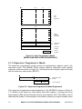
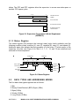
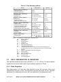
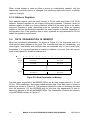

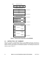
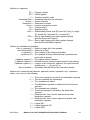
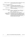
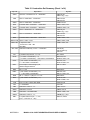
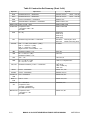
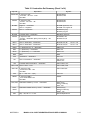
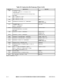
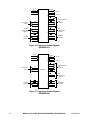

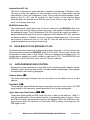
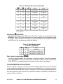
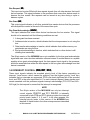
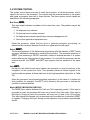

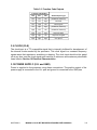

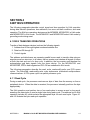
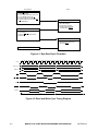
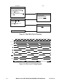
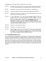
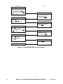
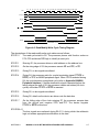

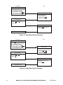
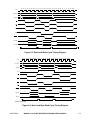
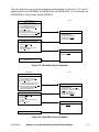
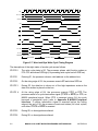
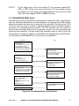

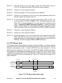
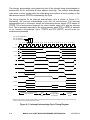
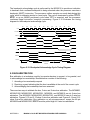
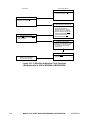
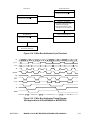
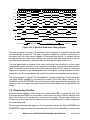
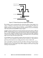


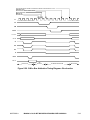
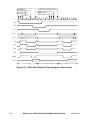


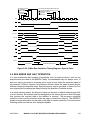
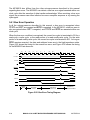
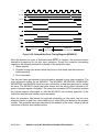
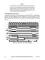
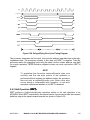
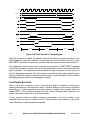
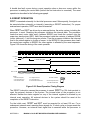
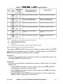
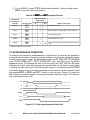
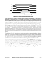
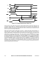
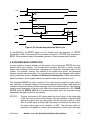

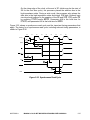
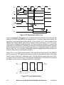


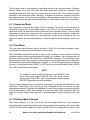
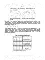
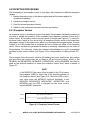
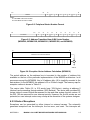

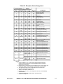
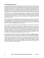
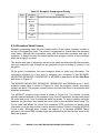
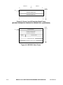
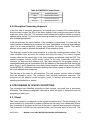
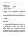
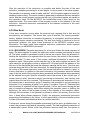
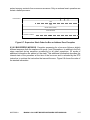

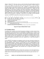
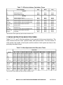
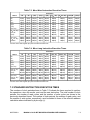
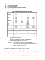
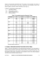
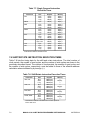
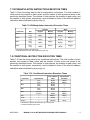
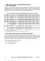
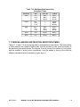
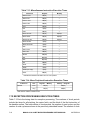
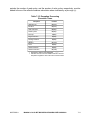
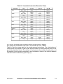
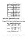
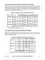
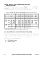
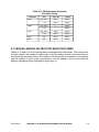
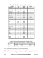
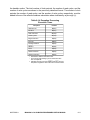
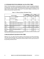
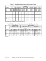
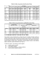
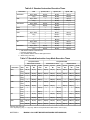
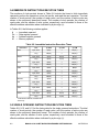
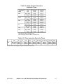
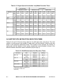
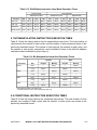
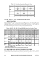
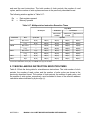
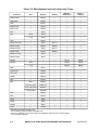
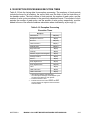
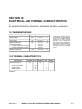
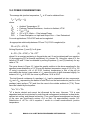
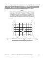
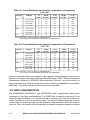

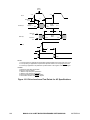
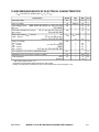
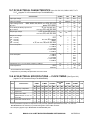
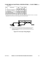
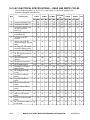
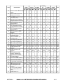
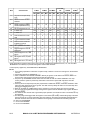
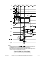

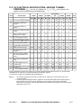
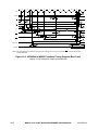
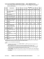
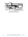
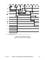

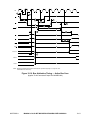
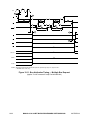
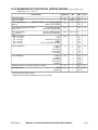
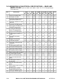
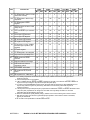
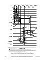


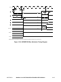
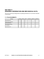
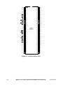
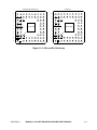
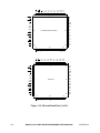
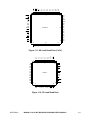

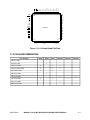

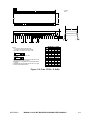
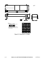
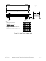

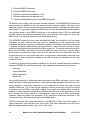
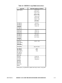



![CPU32 Reference Manual [330 pages!]](http://vs1.manualzilla.com/store/data/005686632_1-79fc9549061344d5fca8ab86e2038cb9-150x150.png)