1
TM
COMMITTED TO:
• INNOVATION
• QUALITY
• PERFORMANCE
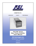
CIRRUS™ Series Counters
User's Manual
FSI Technologies Inc.
668 Western Avenue • Lombard, IL 60148-2097
Phone: (630) 932-9380 • Fax: (630) 932-0016
(800) 468-6009
www.fsinet.com
[email protected]
HISTORY
Founded in 1959, FSI Technologies Inc. Had its beginnings in the design and manufacture of
precision tuning fork time standards, primarily for use in military applications. In the mid 1960’s FSI
entered into the industrial market with a line of high performance logic compatible photoelectric
sensors and controls for factory automation.
During the following years FSI continued development of its sensor line while branching into high
speed IR sensors, optical rotary shaft encoders, machine vision, fiber optics and other leading edge
sensor and control technologies. Presently FSI manufactures state of the art sensors and electronic
products for use in industrial, commercial, military, and medical applications.
IN HOUSE CAPABILITIES
Standard sensors & encoders
Custom sensors & encoders
Application engineering & testing
Electrical & mechanical engineering
Prototype & production machining
Darkroom & technical graphics
Prototype PCB etching & fabrication
PBC & mechanical assembly
The above capabilities and a creative, quality conscious staff make FSI the company of choice for
both standard and custom products. FSI is committed to innovation, quality and customer
satisfaction.
All of us at FSI and our capable network of Distributors look forward to assisting you.
Please call for the location of your nearest Distributor.
(630) 932-9380 - FAX (630) 932-0016 - (800) 468-6009
668 Western Ave., Lombard, IL 60148-2097
Email: [email protected]
Table Of Contents
Section
Page
Introduction
1.0
2
Operation
2.0
3
Dip Switch Setup Guide
3.0
4
3.1
5
Wiring, Mounting, and Dimensions
4.0
8
Cirrus Specifications
5.0
10
Controlling Outputs
6.0
11
Single Preset Counter
6.1
11
Dual Preset Counter
6.2
11
Batch Counter
6.3
12
Resetting the Counter
7.0
13
Calculating the Scale Factor
8.0
13
Example Count Diagrams
9.0
14
Count Up Mode
9.1
14
Count Down Mode
9.2
14
Interval Mode
9.3
15
Quadrature x4 Mode
9.4
15
Ordering Information
10.0
16
Safety
11.0
16
Dip Switch Programming
1
1.0 INTRODUCTION
The Cirrus Series Counter is a predetermining counter that will count high speed unidirectional, bidirectional, or quadrature input signals and will activate an output when the predetermined preset value
is reached. The unit is available in both Single and Dual Preset models, and includes an internal totalizer.
Also, the Cirrus Counter will operate as a Batch Counter using the second preset as a Batch Preset. The
Cirrus comes with a variety of counting modes (some of which are only available in the dual preset
model). The counter allows the users to set:
Count Up from Zero to a given Preset
The Output in the Counter is activated when the Count equals the Preset. In the Dual Preset
Model, the Counter counts up from zero and Output 1 is activated when Preset 1 is reached and
Output 2 is activated when Preset 2 is reached.
Count Down from a Preset to Zero
When Reset is pressed, the Counter is set to the Preset value. When the Count value equals
zero, the Output is activated. In the Dual Preset Model, the Counter counts down from the High
Preset value and activates one Output when it reaches the Low Preset value; the other Output is
activated when the Counter counts down from the Low Preset value and reaches zero.
Interval Mode
In this mode, the Counter will not begin counting until Input 2 is turned ON, indicating a Start
Signal. Once the Start Signal is received, the Output will turn ON and the Counter will count. The
Output will then turn OFF at the preset or zero. The Start Signal must be activated each time the
process is reset, even when the Counter is set to Auto Reset.
Batch Mode - Dual Preset Models only
In the Batch Mode, Input 1 is the Count input and will turn ON at Preset 1. Each time Output 1
turns ON, the Batch Counter will record a count. When the Batch Counter value equals the value
in Preset 2, Output 2 will turn ON. The Batch Mode must be Manually Reset (unless T2 is set to
.5 w/AR (00.00) for Auto Reset).
Timed Outputs
The Outputs can be delayed before turning OFF by setting time delay values for each output.
Once the Preset is reached, a time delay, according to the time value set, will occur before the
Outputs turn OFF. This value can range from 0.00 sec. (OFF at Preset) to 99.99 sec. (Latched
ON). In addition, the outputs can also be set to turn OFF upon reaching the preset for the other
output in the Dual Preset Model.
Scale Factor
A Prescale value can be set to allow viewing and setting counts using real units of measure. The
Prescale value is a multiplier which is applied to the count input(s) to determine the count
display and preset values. The Prescale value can be set from 0.00001 to 9.99999. In addition,
the decimal point can be set on the display to any one of 6 positions.
2
2.0 OPERATION
To operate the Counter, there are four push button keys located on the front of the unit. These buttons
are provided to allow the user to select, change and save various values. These key operations are
dependent on the DIP Switch settings of the unit (see Section 3.0).
1 0 0. 0 4
preset 1
preset 2
SELECT
RESET
ENTER
CANCEL
This figure shows the front of the panel with the Process
Count value displayed. Pressing SELECT will scroll
through a menu of options. After one of these options is
displayed for a second, the value for that option is
automatically displayed. Pressing the < key will move
one digit to the left and the ^ key will increment the
value by one. The SELECT key must be pressed to save
the new value. Pressing RESET will return to the
process count display. The change will not be entered if
SELECT is not pressed. Selections in addition to
Process Count are:
Totalizer: Counts accumulated since last Totalizer Reset. When the total counts
exceeds 99,999,999 the Totalizer display will blink. Pressing RESET will scroll
through the actual value until pressing RESET a final time will reset the value to
Zero.
Batch: Number of cycles elapsed in Batch Mode.
0 0 0 9 9 8 9 8
B
Preset 1/Preset 2: Value compared with the actual count. When the Preset
value is displayed, the Preset LED on the panel will light, indicating which preset
is displayed.
Prescale: This factor will scale the input counts. The count signal is multiplied
by the prescale value (range - 0.00001 to 9.99999) to determine the count
displayed.
Note: If the prescale value is fractional, the output will energize when the count
value passes the preset value.
10
0 0 0 5 0 0
1. 0 0 0 0 0
Output 1/Output 2: Time delay setting for outputs.
L A T C H E D
Decimal: The number of decimal positions for the display.
D P
When the Counter reaches its presets, the output will activate and the LEDs on
the panel will flash, indicating which output is activated.
3
0
3.0 DIP SWITCH SETUP GUIDE
To set up the Counter for operation, a series of DIP switches located inside the unit must be set UP or
DOWN. To access these DIP switches, loosen the two screws on the front panel and pull the unit from its
housing.
LEFT SWITCH
1
2
3
4
5
6
RIGHT SWITCH
7
8
1
2
3
4
5
6
7
8
INPUT COUNT TYPE
(See next page)
UP = NO RESET ON PWR UP
DN = RESET ON PWR UP
UP = HIGH THRESHOLD IN
DN = LOW THRESHOLD IN
UP = NO PANEL RESET
DN = PANEL RESET
UP = NO DEBOUNCE INPUT
DN = DEBOUNCE INPUT
UP = NO ACCESS - T1, T2, SF, DP
DN = ACCESS - T1, T2, SF, DP
UP = SINK INPUT SIGNAL
DN = SOURCE INPUT SIGNAL
UP = NO ACCESS - P1, P2
DN = ACCESS - P1, P2
UP = COUNT UP
DN = COUNT DOWN
UP = DUAL PRESET MODE
DN = BATCH MODE
UP = COUNT AND GO
DN = COUNT AND STOP
UP = TOTALIZER OFF
DN = TOTALIZER ON
(Bold indicates factory default setting)
UP = AUTO RESET AT PRESET
DN = AUTO RESET AT TIME OUT
UP = AUTO RESET OFF
DN = AUTO RESET ON
NOTES:
RIGHT SWITCH Pin 4, DUAL PRESET/BATCH MODE, is only active on Dual Preset Models.
RIGHT SWITCH Pin 2, AUTO RESET AT PRESET/TIME OUT, is active only when RIGHT SWITCH Pin 1 is
set to AUTO RESET ON (DN). The automatic reset takes place after the Preset (or zero) is reached
(depending on the setting of LEFT SWITCH Pin 7, COUNT UP/DOWN) and will occur either immediately
at the Preset, or after the Timed Output value has elapsed. For Dual Preset Mode, the automatic reset
occurs after the highest of the two presets has been reached. For Batch Mode, the automatic reset only
applies to Preset 1 (Count preset). For automatic reset of Preset 2 (Batch preset) in Batch mode refer to
Section 6.3.2.
Changing the RIGHT SWITCH Pins 1,2 & 4 and LEFT SWITCH Pins 1,2 & 3 may cause the counter to
load the default P1, P2, T1, T2, SF, and DP values of 500, 1000, 00.01, 00.01, 1.00000 and 0,
respectively.
4
3.1 DIP SWITCH PROGRAMMING
3.1.1 LEFT DIP SWITCH
Pins 1,2, and 3 - the first three DIP switches define how the input count signals, Input 1 and Input 2, will
be read. Determine which of the six available settings in needed for your application and set the switches
accordingly:
LEFT SWITCH
INPUT COUNT TYPE:
Single and Bi - directional Counter
Input 1 = Count signal
Input = Directional Signal
Counter will count the trailing edges of input 1.
Counter will read a positive count when Input 2 is LOW
and will read a negative count when Input 2 is HIGH.
Quadrature Counter
Input 1 = Quadrature Count Signal
Input 2 = Directional Signal
Input 1 will count the trailing edges of the input signal.
If Input 2 trails, the Counter will read a positive count.
If Input 2 leads, the Counter will read a negative count.
Quadrature Count x 2
Input 1 = Quadrature Count Signal x 2
Input 2 = Directional Signal
The leading and trailing edges of Input 1 are counted.
If Input 2 trails, the Counter will read a positive count.
If Input 2 leads, the Counter will read a negative count.
Quadrature Count x 4
Input 1 = Count Signal x 2
Input 2 = Directional Count Signal x 2
Same as Quadrature Count x 2 except that the leading
and trailing edges of the Input 2 are also counted.
Count with Inhibit
Input 1 = Count Signal
Input 2 = Halts Input 1 counting when active.
Counter will count the trailing edges of Input 1 and read
positive counts only when Input 2 is OFF. When Input 2 is
ON, no counts are read.
Interval Mode (Counter with Start Signal Input)
Input 1 = Count Signal
Input 2 = Start Signal
The Outputs will turn ON when Input 2 (Start Signal) is
turned ON. Counter will count the trailing edges of
Input 1 and register positive counts only after the Start
Signal is detected. When the Preset(s) are reached and
Timed Output values have elapsed, the Outputs will
turn OFF.
5
1
2
3
UP UP UP
DN UP UP
UP DN UP
DN DN UP
UP UP DN
DN UP DN
Pin 4 determines the threshold level for the Input Signal is:
High (UP):
Low (DN):
5.5 V & 7.5 V trigger levels (Proximity Switch)
1.5 V & 3.75 V trigger levels (TTL)
Pin 5 determines if the signals from Input 1 are filtered before being counted.
No Debounce (UP):
Debounce (DN):
Signal is unfiltered with a max. freq. of 10 kHz.
Signal is filtered to a max. freq. of 100 Hz.
Pin 6 determines whether the Inputs 1 and 2 operate as:
Sinking (UP):
Sourcing (DN):
Max. Current = 1.25 mA.
Max. Voltage = 30 VDC @ 7 mA.
Pin 7 determines the counting mode of the device:
Count Up Mode (UP):
Count Down Mode (DN)
The input will count up from zero and
the output(s) will switch at their preset values(s).
The input will count down from the high preset
and the output will switch at zero. For Dual
Preset Mode, the other output will switch at
the low preset.
Pin 8 determines the status of the Process Counter:
Count and Go (UP):
Count and Stop (DN):
The Counter continues to accumulate counts
after the preset is reached (or past zero).
The Counter stops accumulating counts after
the high preset is reached (or at zero).
3.1.2 RIGHT DIP SWITCH
Pin 1 determines whether the Counter will automatically reset or not:
Auto Reset Off (UP):
Auto Reset On (DN):
The Counter will not automatically reset.
The Counter will automatically reset upon
reaching the high preset (or zero). The reset
will occur either immediately or after the Timed
Output value has elapsed.
(See RIGHT SWITCH Pin 2).
Note: Auto Reset does not apply to the Batch
Counter when in Batch Counting Mode. Refer
to Section 7.0 for addition information on
Auto Reset.
Pin 2 determines when the Auto Reset will occur (RIGHT SWITCH Pin 1 must be set DOWN - Auto
Reset On):
The Counter will automatically reset after the high
Reset at Preset (UP):
preset is reached (or at zero).
The Counter will continue counting after the high
Reset at Time-out (DN):
preset is reached (or at zero) until the Timed Output
value has elapsed, and then will automatically
reset.
6
Pin 3 determines if the Totalizer Counter is active:
Totalizer Off (UP):
Totalizer ON (DN):
The Totalizer is disabled.
The Totalizer is enabled and will count all pulses
into the unit. The Totalizer can be reset
by displaying the Totalizer value on the display and
pressing the Reset button.
Pin 4 sets the Dual Preset Model to DUAL PRESET or BATCH MODE (this
switch is not active on Single Preset models):
Dual Preset Mode (UP):
Batch Mode (DN):
In the Dual Preset Mode, Preset 1 is the Preset for
Output 1 and, Preset 2 for Output 2.
In the Batch Mode, Preset 1 is the target Count
value for Output 1 and Preset 2 is the number of
cycles that will occur in the Batch process, before
Output 2 switches.
Pin 5 establishes operator access to Preset 1 and Preset 2:
No Access - P1/P2 (UP):
Access - P1/P2 (DN):
This prevents access to these Presets from the
front panel during operation.
This allows the Preset values to be adjusted
from the front panel during operation.
Pin 6 establishes operator access to the values of Timed Output 1, Timed
Output 2, Scale Factor, and Decimal Point position.
No Access - T1, T2, SF, DP (UP):
Access to - T1, T2, SF, DP (DN):
This prevents access to these values from the
front panel during operation.
This allows these values to be
adjusted from the front panel during the process.
Pin 7 determines whether the Reset Key on the panel is active during operation:
No Panel Reset (UP):
Panel Reset (DN)
The count can not be reset by pressing the Reset
Key on the panel. (Note: the three hardware reset
terminals are always active and are not affected
by this setting.)
The displayed Count, Batch or Totalizer value will be
reset when the Reset Key is pressed.
Pin 8 determines whether the Counter will reset when power is lost.
No Reset on Power Up (UP):
Reset on Power Up (DN):
The Counter will resume counting from where
it was before the power loss. (Note: any Outputs that
were ON before the power loss will be set to OFF when
power is restored.)
If power is lost, the Counter will reset when
power is restored.
7
4.0 WIRING, MOUNTING, AND DIMENSIONS
TERMINALS
13
14
12
N.C.
OUT1
10
11
N.O.
N.O.
9
N.C.
OUT2
8
7
BATCH
RST
TOT
RST
L1
L2
+12 VDC
AUX PWR
AUX
COM
IN1
IN2
IN
COM
CNT
RST
1
2
3
4
5
6
15
16
OUTPUT WIRING
14
13
12
OUT 1
14
13
12
9
10
11
OUT 2
9
10
11
N.O.
RELAY
NPN TRANSISTOR
(Open Collector)
COUNT INPUT WIRING - SINK INPUT SIGNAL (Left Switch Pin 6 - UP)
2 WIRE DC
3 WIRE DC
RELAY
+
OUT
(NPN)
(NPN)
+
5
6
15
5
6
15
3
5
IN1
IN2
IN
COM
IN1
IN2
IN
COM
12 VDC
AUX
PWR
IN1
Note:
Note:
Counter will read positive counts with terminal 6 not connected.
For negative counts, connect terminal 6 to terminal 15.
For Count Inhibit or Interval Mode Start, wire terminal 6 in the same
manner as terminal 5.
8
6
IN2
15
IN
COM
4.0 WIRING, MOUNTING, AND DIMENSIONS (Continued)
COUNT INPUT WIRING - SOURCE INPUT SIGNAL (Left Switch Pin 6 - DN)
+
2 WIRE DC
3 WIRE DC
RELAY
(PNP)
+
(PNP)
OUT
5
6
3
5
6
3
5
6
3
4
IN1
IN2
12 VDC
AUX
PWR
IN1
IN2
12 VDC
AUX
PWR
IN1
IN2
12 VDC
AUX
PWR
AUX
PWR
COM
Note:
Counter will read positive counts with terminal 6 not connected.
For negative counts, connect terminal 6 to terminal 3.
For Count Inhibit or Interval Mode Start, wire terminal 6 in the same
manner as terminal 5.
Note:
ENCODER INPUT WIRING
SINK INPUT SIGNAL
(Left Switch Pin 6 - UP)
+ (B)
- (A)
QUADRATURE
ENCODER
(NPN)
RESET INPUT WIRING
(Sink Input Signals)
OUTPUT COM (F)
2 WIRE
DC
(NPN) +
RELAY
CHAN
B
(E)
CHAN A (D)
3 WIRE
+
DC
(NPN) OUT
3
4
5
6
15
15
16
8
7
3
12 VDC
AUX
PWR
AUX
PWR
COM
IN1
IN2
IN
COM
IN
COM
CNT
RST
COM
BATCH
RST
TOT
RST
12 VDC
AUX
PWR
MOUNTING AND DIMENSIONS
PANEL CUTOUT SHOWING DISTANCE
BETWEEN ADJACENT CUTOUTS.
INCHES
MILLIMETERS
1.10
27.95
2.83
72.00
3.63 MIN
92.20
5.31
134.87
2.58
65.53
2.83
72.00
2.64
67.00 SQ.
9
5.0 CIRRUS SPECIFICATIONS
Settings (Front Panel):
Presets: 1 to 999,999
Scale Factor: 0.00001 to 9.99999
Timed Outputs: 00.01 to 99.98 sec.
Latched
Off at Preset
Decimal Positions: 0 to 6
Remote Resets:
Count, Batch, Totalizer
Min. 15 ms. pulse
Pulled to 5V via 8K ohm res.
Active Low. ViL = 0.5 V Max.
Max. current = .625 ma.
Output - Solid State:
Current Sinking
I sink = 100 ma Max.
VoL = 1.0 VDC Max.
Max. Voltage = 30 VDC
Count Input Modes:
(Switch Selectable)
Bi - Directional
Quadrature X1
Quadrature X2
Quadrature X4
Count with Inhibit
Interval with Start Input
Output - Relay:
Life - 100 million operations (no
load). Contact Rating - 10 amp.
30 VDC or 250 VAC, 1/3 HP.
Operating Features:
(Switch Selectable)
Count Up or Count Down
Count/Go or Count/Stop
Sink or Source Count Input
High or Low Threshold (Bias)
Auto Reset at:
High preset (Count Up)
Zero (Count Down)
After Timed output
Totalizer
Dual Preset / Batch mode
Security lockout:
Access to Presets
Access to T1, T2, SF, DP
Front panel Reset
Reset on Power Up
DC supply for external sensors:
12 VDC Regulated, +/- 4%.
Max. current = 120 ma.
Memory:
Non-Volatile EEPROM.
196,000 power losses min.
10 Year Retention
Models:
Single and Dual Preset with
either NPN (Solid State) or Relay
Outputs.
Power:
Maximum Counting Frequency:
10 kHz - Count Up mode
9 kHz - Count Down Mode
(Reduce by 3 kHz when
Totalizer Counter is enabled).
(Reduce by 2 kHz when Auto
Reset is enabled).
Min. pulse 10 usec. on: 90 usec. off.
Count Inputs:
Sink - 9.4 K ohm pull up.
Max. current = 1.25 ma.
Source - 4.7 K ohm pull down.
Max. voltage = 30 VDC @ 7 ma.
High Bias: ViL = 5.5 V Max.
ViH = 7.5 V Min.
Low Bias: ViL = 1.5 V Max.
ViH = 3.75 V Min.
120 VAC: 95 - 132 VAC
240 VAC: 190 - 264 VAC
50 / 60 Hz.
Max. power = 8 VA.
Display:
8 Digit, 14 Segment
5 mm. X 4.1 mm. (0.2" x 0.16")
Blue Vacuum Fluorescent
Housing:
Plug in.
72 mm. sq. DIN Plug in. Fully
Gasketed. Dust and Water tight.
Terminals:
16 screw terminals
accessible from rear.
Operating Temperature:
0° F to 140° F.
-20° C to 60° C
Debounce - reduces count Input 1
to 100 Hz. (Input 2 no debounce).
Humidity:
0% to 80% RH
Non-condensing
Interval start requires
15 msec min. pulse.
(Can be momentary or sustained).
10
6.0 CONTROLLING OUTPUTS
6.1 SINGLE PRESET COUNTER
Time Delayed Output
To make the output remain energized for a time delay, set the Output 1 value to a time value. This time
value can be set to a range of 00.01 to 99.98 seconds. Upon reaching the preset, the output will remain
ON for this period of time, or until it is reset via the Reset key on the panel or the external Count Reset
input.
Latched Output
(Note: Auto Reset must be set OFF for the Latched output setting to be allowed (RIGHT SWITCH
PIN 1 - UP). Also, the Latched output setting is not active when the Counter is set for Interval Mode).
To latch the output ON until the Counter is reset, set the Output 1 value to 99.99. The display will show
"LATCHED". Upon reaching the preset, the output will remain ON until it is reset via the Reset key on
the panel or the external Count Reset input.
Output OFF at Preset
(Note: The Counter must be set to Interval Mode for the OFF at Preset setting to be allowed). To make
the output turn OFF upon reaching the preset, set the Output 1 value to 00.00, the display will show
"OFF at P1". (If the Counter is set to Count Down the display will show "OFF AT 0"). Upon reaching the
preset, the output will turn OFF.
6.2 DUAL PRESET COUNTER
Time Delayed Output
To make either output remain energized for a time delay, set the Output 1 and/or the Output 2 value to a
time value. This time value can be set to a range of 00.01 to 99.98 seconds. Upon reaching the preset,
the output will remain ON for this period of time, or until it is reset via the Reset key on the panel or the
external Count Reset input.
Latched Output
(Note: Auto Reset must be set OFF for the Latched output setting to be allowed (RIGHT SWITCH
PIN 1 - UP). Also, the Latched output setting is not active when the Counter is set for Interval Mode). To
latch either output ON until the Counter is reset, set the Output 1 and/or the Output 2 value to 99.99.
The display will show "LATCHED". Upon reaching the preset, the output will remain ON until it is reset
via the Reset key on the panel or the external Count Reset input.
Output ON at Low Preset, OFF at High Preset
To make the output controlled by the lower preset turn OFF at the higher preset, set the Output value of
the output controlled by the lower preset to 00.00. If Output 1 has the lower preset, the Output 1 value
display will show "OFF AT P2". If Output 2 has the lower preset, the Output 2 value display will show
"OFF AT P1". (If the Counter is set to Count Down the output value display will show "OFF AT 0"). Upon
reaching the Low Preset, the output will remain ON until the High Preset is reached, or until it is reset via
the Reset key on the panel or the external Count Reset input.
11
6.2 DUAL PRESET COUNTER (continued)
Output OFF at Preset
(Note: The Counter must be set to Interval Mode for the OFF at Preset setting to
be allowed). To make either output turn OFF upon reaching the preset, set the
Output value to 00.00. The display will show "OFF at P1" for Output 1 or "OFF
at P2" for Output 2. (If the Counter is set to Count Down the display will show
"OFF at 0"). Upon reaching the preset, the output will turn OFF.
6.3 BATCH COUNTER
6.3.1 Output 1 - Process Counter
When the Counter is set up as a Batch Counter, Output 1 operates the same as the
Single Preset Counter. Refer to Section 6.1 for operation of this output.
6.3.2 Output 2 - Batch Counter
Time Delayed Output
To make Output 2 remain energized for a time delay, set the Output 2 value to a
time delay value. This time value can be set to a range of 00.01 to 99.98 seconds.
Upon reaching Preset 2 (Batch Preset), Output 2 will remain ON for this period of
time, or until it is reset via the Reset key on the panel or the external Batch Reset
input.
Latched Output
To latch Output 2 ON until the Batch Counter is reset, set the Output 2 value to
99.99. The display will show "LATCHED". Upon reaching Preset 2 (Batch
Preset), Output 2 will remain ON until it is reset via the Reset key on the panel or
the external Batch Reset input.
Pulse for .5 sec and Automatically Reset the Batch Counter
To make Output 2 turn on for .5 seconds and automatically reset the Batch Counter
upon reaching Preset 2 (Batch Preset), set the Output 2 value to 00.00. the display
will show ".5 W/AR". Upon reaching Preset 2 (Batch Preset), Output 2 will
turn ON for .5 sec and the Batch Counter will automatically reset, allowing inputs
for the next batch to counted. This allows the Batch Counter to automatically
repeat its cycle without being manually reset via the Reset key on the panel or the
external Batch Reset input.
Note: When Preset 2 is to ".5 W/AR" and the Counter is set to Auto Reset
(RIGHT SWITCH, PIN 1 - DN), The maximum count frequency is reduced
by 4 kHz.
12
7.0 RESETTING THE COUNTER
7.1 Manual Reset
The Counter can be manually reset via the Reset key on the panel or via the external Reset inputs.
Pressing the Reset key on the panel will reset the Counter which is currently displayed on the panel. To
reset the Process Counter, press the Reset key when the Process Count is being displayed. To reset the
Batch Counter, press the Reset key when the Batch Count is displayed. To reset the Totalizer, press the
Reset key when the Totalizer Count is displayed. The three external Reset inputs will reset the Process,
Batch, or Totalizer Counters when activated.
Reset of the Counters will occur within 15 msec. of a signal being received by the Reset key on the panel
or from the external Reset inputs. Upon reset, the appropriate outputs will turn OFF and the Counter will
be reset to zero (or the high preset for count down mode). The Counter will not read count inputs while
the reset signal is being received. When the reset signal is removed, the Counter will again begin to
count.
7.2 Auto Reset (RIGHT SWITCH, PIN 1 -DN)
Auto Reset allows the Counter to automatically reset upon reaching the high preset (or zero for count
down). The Auto Reset will occur either immediately at the high preset, or after the Output time delay has
elapsed, depending on the position of RIGHT SWITCH, PIN 2. This allows the Counter to operate with
repeating cycles, without waiting for a manual reset signal from the Reset key on the panel or the
external Count Reset input.
Note: Auto Reset will only reset the Process Count value. The outputs will remain ON until the Output
time delay has elapsed. Auto Reset does not affect the Batch Count. To Auto Reset the Batch Count,
refer to Section 6.3.2.
Note: When the Counter is set to Auto Reset, the maximum count frequency is reduced by 2 kHz.
8.0 CALCULATING THE SCALE FACTOR
The Prescale value is factory set to provide 1 count on the display for each input pulse received by the
Counter. To make the display show real units, such as "gallons" or "feet", set the prescale value to
calculate these units for the display. The Prescale value is determined as follows:
PRESCALE VALUE = DISPLAY UNITS / NUMBER OF PULSES
The DISPLAY UNITS represents the number of units that should be displayed after the NUMBER OF
PULSES has been counted.
The NUMBER OF PULSES is the number of pulses required to achieve the DISPLAY UNITS.
The Prescale value can be set from 0.00001 to 9.99999.
13
9.0 EXAMPLE COUNT DIAGRAMS
9.1 COUNT UP MODE / DUAL PRESET / MANUAL RESET / NO OUTPUT DELAY
LEFT SWITCH
RIGHT SWITCH
U
U
U
U
U
U
U
U
U
U
U
U
D
D
D
U
1
2
3
4
5
6
7
8
1
2
3
4
5
6
7
8
Preset Values:
Low Preset (P1) = 3
High Preset (P2) = 5
Output 1 (T1) = Latched
Output 2 (T2) = Latched
PROCESS
0
1
(Range: 1 to 999,999)
(Range: 1 to 999,999)
(Range: Off at P2/ 0.01 to 99.98 / Latched)
(Range: 0.01 to 99.98 / Latched)
2
3
4
5
7
6
8
9
INPUT 1
OUTPUT LOW
MANUAL RESET
OUTPUT HIGH
9.2 COUNT DOWN MODE / DUAL PRESET / AUTO RESET / AFTER TIME OUT
LEFT SWITCH
RIGHT SWITCH
U
U
U
U
U
U
D
U
D
D
U
U
D
D
D
U
1
2
3
4
5
6
7
8
1
2
3
4
5
6
7
8
Preset Values:
Low Preset (P1) = 3
High Preset (P2) = 5
Output 1 (T1) = 2.0
Output 2 (T2) = 4.0
PROCESS
5
4
(Range: 1 to 999,999)
(Range: 1 to 999,999)
(Range: Off at Zero/0.01 to 99.98)
(Range: 0.1 to 99.98)
3
2
1
0
-1
-2
INPUT 1
OUTPUT LOW
T1 = 2.0
AUTO RESET
OUTPUT HIGH
T2 = 4.0
14
5
4
9.3 INTERVAL MODE / COUNT DOWN MODE / DUAL PRESET / MANUAL RESET
LEFT SWITCH
RIGHT SWITCH
D
U
D
U
U
U
D
U
U
U
U
U
D
D
D
U
1
2
3
4
5
6
7
8
1
2
3
4
5
6
7
8
Preset Values:
Low Preset (P1) = 3
High Preset (P2) = 5
Output 1 (T1) = Off at P1
Output 2 (T2) = Off at 0
PROCESS
5
(Range: 1 to 999,999)
(Range: 1 to 999,999)
(Range: Off at P1 / 0.01 to 99.98)
(Range: Off at 0 / 0.01 to 99.98)
4
3
2
1
0
-1
5
INPUT 1
OUTPUT LOW
OUTPUT HIGH
START SIGNAL
MANUAL RESET
START SIGNAL
9.4 QUADRATURE x 4 / COUNT DOWN MODE / BATCH MODE / BATCH AUTO RESET
LEFT SWITCH
RIGHT SWITCH
D
D
U
U
U
U
D
U
D
D
U
D
D
D
D
U
1
2
3
4
5
6
7
8
1
2
3
4
5
6
7
8
Preset Values:
Count Preset (P1) = 16
Batch Preset (P2) = 2
Output 1 (T1) = 0.5
Output 2 (T2) = 0.5 sec. with Auto Reset*
(Range: 1 to 999,999)
(Range: 1 to 999,999)
(Range: 0.01 to 99.98)
(Range: .5 with AR / 0.01 to 99.98 / Latched)
* This is the only way to Auto Reset the Batch Count.
PROCESS
16
12
8
4
16
12
8
4
16
INPUT 1
INPUT 2
BATCH AUTO RESET
OUTPUT 1 (P1)
1
0
OUTPUT 2 (BATCH - P2)
15
10.0 ORDERING INFORMATION
CRS - _ _ - _ _ _ - _ _ _ - _
BASIC MODEL TYPE
PRESETS
SP
Single Preset
DP
Dual Preset (w/ Batch)
VOLTAGE / FREQUENCY
120
120 VAC, 50/60 Hz
240
240 VAC, 50/60 Hz
OUTPUT TYPE
NPN
RLY
NPN Transistor
Relay
FEATURES
NONE
X
Standard
Special
11.0 A WORD ABOUT SAFETY
Most of FSI's products are designed for general and not for specific applications. Because of this, we usually are not
aware of how they eventually will be used. However, they are frequently employed in controlling automatic
machinery or processes.
Although FSI makes products of high reliability, every product, given enough time, can be expected to fail.
Statistically, devices can fail after a short period of time or a long period of time or anything in between. In essentially
all cases, failure means (1) failure to provide a logic signal or power to an electrical load when it should or (2) the
providing of such a signal or power when it should be absent. Less often, failure means failure to meet some other
specification. But, in all cases, it means to do something unwanted or unexpected.
Since the failure of automatic machinery or processes can create hazardous conditions for personnel or property,
whatever the definition of failure might be, it is necessary to consider the consequences of failure and design the
application in which the FSI product is used so that failure will not create a hazard to personnel or property. The
design must insure that any failure will result in a fail-safe condition and there will be no danger to personnel and/or
property involved in the use of the product. FSI products are not intended for use as final safety devices.
Designs incorporating controls of any kind should be carefully considered to provide for their eventual
failure.
IMPORTANT NOTICE:
The use of this product is beyond the control of the manufacturer, no guarantee or warranty, expressed or implied, is
made as to such effects incidental to such use, handling or possession or the results to be obtained, whether in
accordance with the directions of the claimed so to be. The manufacturer expressly disclaims responsibility
therefore. Furthermore, nothing contained herein shall be construed as a recommendation to use any product in
conflict with existing laws and/or patents covering any material or use.
Warranties of Sale, disclaimer thereof and limitations of liability are covered exclusively by FSIs' printed warranty
statement for controls. These instructions do not expand, reduce, modify or alter FSIs' warranty statement and no
warranty or remedy in favor of a customer or any other person arises out of these instructions.
16
Over 750 Distributors within North America to Serve You
TM
TM
668 Western Avenue Lombard, IL. 60148-2097
ph: 800-468-6009 fax: 630-932-0016 [email protected] www.fsinet.com
© 2006 FSI Technologies Inc. All rights reserved.
Bulletin # 2952-8600-31
TM
Printed in U.S.A. by FSI Press