1
Agilent 1260 Infinity
Standard Autosampler
User Manual
Agilent Technologies
Notices
© Agilent Technologies, Inc. 2007-2012,
2013
No part of this manual may be reproduced
in any form or by any means (including electronic storage and retrieval or translation
into a foreign language) without prior agreement and written consent from Agilent
Technologies, Inc. as governed by United
States and international copyright laws.
Manual Part Number
G1329-90015 Rev. B
Edition
04/2013
Printed in Germany
Agilent Technologies
Hewlett-Packard-Strasse 8
76337 Waldbronn
This product may be used as a component of an in vitro diagnostic system if the system is registered with
the appropriate authorities and complies with the relevant regulations.
Otherwise, it is intended only for general laboratory use.
Warranty
The material contained in this document is provided “as is,” and is subject to being changed, without notice,
in future editions. Further, to the maximum extent permitted by applicable
law, Agilent disclaims all warranties,
either express or implied, with regard
to this manual and any information
contained herein, including but not
limited to the implied warranties of
merchantability and fitness for a particular purpose. Agilent shall not be
liable for errors or for incidental or
consequential damages in connection
with the furnishing, use, or performance of this document or of any
information contained herein. Should
Agilent and the user have a separate
written agreement with warranty
terms covering the material in this
document that conflict with these
terms, the warranty terms in the separate agreement shall control.
receive no greater than Restricted Rights as
defined in FAR 52.227-19(c)(1-2) (June
1987). U.S. Government users will receive
no greater than Limited Rights as defined in
FAR 52.227-14 (June 1987) or DFAR
252.227-7015 (b)(2) (November 1995), as
applicable in any technical data.
Safety Notices
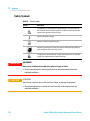
CAUTION
A CAUTION notice denotes a
hazard. It calls attention to an
operating procedure, practice, or
the like that, if not correctly performed or adhered to, could
result in damage to the product
or loss of important data. Do not
proceed beyond a CAUTION
notice until the indicated conditions are fully understood and
met.
Technology Licenses
The hardware and/or software described in
this document are furnished under a license
and may be used or copied only in accordance with the terms of such license.
Restricted Rights Legend
If software is for use in the performance of a
U.S. Government prime contract or subcontract, Software is delivered and licensed as
“Commercial computer software” as
defined in DFAR 252.227-7014 (June 1995),
or as a “commercial item” as defined in FAR
2.101(a) or as “Restricted computer software” as defined in FAR 52.227-19 (June
1987) or any equivalent agency regulation
or contract clause. Use, duplication or disclosure of Software is subject to Agilent
Technologies’ standard commercial license
terms, and non-DOD Departments and
Agencies of the U.S. Government will
WA R N I N G
A WARNING notice denotes a
hazard. It calls attention to an
operating procedure, practice,
or the like that, if not correctly
performed or adhered to, could
result in personal injury or
death. Do not proceed beyond a
WARNING notice until the indicated conditions are fully understood and met.
Agilent 1260 Infinity Standard Autosampler User Manual
In This Book
In This Book
This manual covers the Agilent 1260 Infinity Standard Autosampler (G1329B).
1 Introduction to the Autosampler (ALS)
This chapter gives an introduction to the autosampler and instrument
overview.
2 Site Requirements and Specifications
This chapter provides information on environmental requirements, physical
and performance specifications.
3 Installing the Autosampler
This chapter provides information on unpacking, checking on completeness,
stack considerations and installation of the module.
4 Using the Autosampler
This chapter provides information on how to set up the module for an analysis
and explains the basic settings.
5 Optimizing Performance
This chapter provides information on how to optimize the module.
6 Troubleshooting and Diagnostics
Overview about the troubleshooting and diagnostic features.
7 Error Information
This chapter describes the meaning of error messages, and provides
information on probable causes and suggested actions how to recover from
error conditions.
Agilent 1260 Infinity Standard Autosampler User Manual
3
In This Book
8 Maintenance
This chapter describes the maintenance of the module.
9 Parts and Materials for Maintenance
This chapter provides information on parts for maintenance.
10 Identifying Cables
This chapter provides information on cables used with the module.
11 Hardware Information
This chapter describes the detector in more detail on hardware and
electronics.
12 Appendix
This chapter provides addition information on safety, legal and web.
4
Agilent 1260 Infinity Standard Autosampler User Manual
Contents
Contents
1 Introduction to the Autosampler (ALS)
9
Introduction to the Autosampler (ALS)
10
2 Site Requirements and Specifications
21
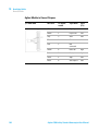
Site Requirements 22
Physical Specifications 25
Performance Specifications Standard Autosampler
3 Installing the Autosampler
27
Unpacking the Autosampler 28
Optimizing the Stack Configuration
Installing the Autosampler 32
Flow Connections 35
Installing the Sample Tray 37
Transporting the Autosampler 38
4 Using the Autosampler
26
29
39
Sample Trays 40
Choice of Vials and Caps
42
5 Optimizing Performance
45
Optimization for Lowest Carry-over 46
Fast Injection Cycle and Low Delay Volume
Precise Injection Volume 51
Choice of Rotor Seal 53
6 Troubleshooting and Diagnostics
49
55
Overview of the Module’s Indicators and Test Functions
Status Indicators 57
Maintenance Functions 59
ALS Step Commands 66
Agilent 1260 Infinity Standard Autosampler User Manual
56
5
Contents
Troubleshooting 68
Troubleshooting Guide for the Sample Transport Assembly
Agilent Lab Advisor Software 77
7 Error Information
70
79
What are Error Messages 81
General Error Messages 82
Autosampler Error Messages 88
8 Maintenance
101
Introduction to Maintenance 102
Cautions and Warnings 103
Updating the Firmware 105
Cleaning the Module 106
Safety Flap, Flex Board 107
Transport Assembly Parts 108
Maintenance Functions 109
Simple Repairs 110
Exchanging the Needle Assembly 111
Exchanging the Needle-Seat Assembly 114
Exchanging the Rotor Seal 116
Exchanging the Metering Seal and Piston 120
Exchanging the Gripper Arm 124
Exchanging the Interface Board 126
Replacing the Module’s Firmware 127
9 Parts and Materials for Maintenance
Main Assemblies 130
Analytical-Head Assembly 132
Vial Trays 134
Standard Autosampler Accessory Kit
Maintenance Kit 137
Injection Upgrade Kit 138
Multi-Draw Kit 139
External Tray 140
6
129
136
Agilent 1260 Infinity Standard Autosampler User Manual
Contents
10 Identifying Cables
141
Cable Overview 142
Analog Cables 144
Remote Cables 146
BCD Cables 149
External Contact Cable 151
CAN/LAN Cables 152
Auxiliary Cable 153
RS-232 Cables 154
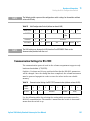
11 Hardware Information
155
Firmware Description 156
Interfaces 159
Setting the 8-bit Configuration Switch 166
Electrical Connections 170
Early Maintenance Feedback (EMF) 172
Instrument Layout 173
12 Appendix
175
General Safety Information 176
The Waste Electrical and Electronic Equipment (WEEE) Directive
(2002/96/EC) 179
Lithium Batteries Information 180
Radio Interference 181
Solvent Information 182
Sound Emission 184
Agilent Technologies on Internet 185
Agilent 1260 Infinity Standard Autosampler User Manual
7
Contents
8
Agilent 1260 Infinity Standard Autosampler User Manual
Agilent 1260 Infinity Standard Autosampler User Manual
1
Introduction to the Autosampler (ALS)
Introduction to the Autosampler (ALS)
Sampling Sequence 12
Sampling Unit 15
Transport Assembly 18
10
This chapter gives an introduction to the autosampler and instrument overview.
Agilent Technologies
9
1
Introduction to the Autosampler (ALS)
Introduction to the Autosampler (ALS)
Introduction to the Autosampler (ALS)
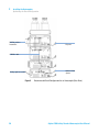
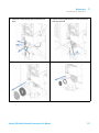
6cVani^XVa]ZVY
<g^eeZgVgb
CZZYaZhZVi
K^VaigVn
Hl^iX]^c\kVakZ
Figure 1
Overview of the Autosampler
The Agilent 1260 Infinity autosampler is designed for use with other modules
of the Agilent 1200 Infinity Series, 1200 Series and 1100 Series LC, or with
other LC systems if adequate remote control inputs and outputs are available.
The autosamplers are controlled by the Agilent Instant Pilot (G4208A) or by
Agilent control software (OpenLAB CDS, ChemStation for LC, EZChrom Elite
etc.).
Three sample-rack sizes are available for the autosampler. The standard
full-size rack holds 100 × 1.8 mL vials, while the two half-size racks provide
space for 40 × 1.8 mL vials and 15 × 6 mL vials respectively. Any two half-size
rack trays can be installed in the autosampler simultaneously. A specially
designed sample-rack holding 100 × 1.8 mL vials is available for use with
thermostatted autosamplers. The half-size racks trays are not designed for an
optimal heat transfer when they are used with a thermostatted autosampler.
10
Agilent 1260 Infinity Standard Autosampler User Manual
Introduction to the Autosampler (ALS)
Introduction to the Autosampler (ALS)
1
The autosampler's transport mechanism uses an X-Z-Theta movement to
optimize vial pick-up and return. A gripper arm picks up the vials and
positions them below the sampling unit. The gripper transport mechanism and
sampling unit are driven by motors. Movement is monitored by optical sensors
and optical encoders to ensure correct operation. The metering device is
always flushed after injection to ensure minimum carry-over. The standard
analytical head of the metering device provides injection volumes from 0.1 –
100 μL and can be operated at up to 600 bar. A head with extended volume is
available for injection volumes from 0.1 – 900 μL and can be operated up to
400 bar (G1329B) or 200 bar (G1329A).
The six-port injection valve unit (only 5 ports are used) is driven by a
high-speed hybrid stepper motor. During the sampling sequence, the valve unit
bypasses the autosampler, and directly connects the flow from the pump to
the column. During injection and analysis, the valve unit directs the flow
through the autosampler. This ensures that all the sample is completely
injected into the column. Any sample residue is removed from the metering
device and from the needle before the next sampling sequence begins.
For applications that require control of the vial temperature, the module can
be combined with the Agilent 1290 Infinity Thermostat (G1330B). The
combination of the autosampler with the thermostat is called a "thermostatted
autosampler". For more details refer to the documentation of the 1290 Infinity
Thermostat.
Agilent 1260 Infinity Standard Autosampler User Manual
11
1
Introduction to the Autosampler (ALS)
Introduction to the Autosampler (ALS)
Sampling Sequence
The autosampler processor continuously monitors the movements of the
autosampler components during the sampling sequence. The processor
defines specific time windows and mechanical ranges for each movement. If a
specific step of the sampling sequence can’t be completed successfully, an
error message is generated.
During the sampling sequence the solvent bypasses the autosampler via the
injection valve. The gripper arm selects the sample vial, either from a static
sample rack, or from external vial positions. The gripper arm places the
sample vial below the injection needle. The required volume of sample is
drawn into the sample loop by the metering device. Sample is applied to the
column when the injection valve returns to the mainpass position at the end of
the sampling sequence.
The sampling sequence occurs in the following order:
1 The injection valve switches to the bypass position.
2 The piston of the metering device moves to the initialization position.
3 The gripper arm moves from the home position, and selects the vial. At the
same time, the needle lifts out of the seat.
4 The gripper arm places the vial below the needle.
5 The needle lowers into the vial.
6 The metering device draws the defined sample volume.
7 The needle lifts out of the vial.
8 If the automated needle wash is selected (see “Using the Automated Needle
Wash” on page 46), the gripper arm replaces the sample vial, positions the
wash vial below the needle, lowers the needle into the vial, then lifts the
needle out of the wash vial.
9 The gripper arm checks if the safety flap is in position.
10 The gripper arm replaces the vial, and returns to the home position.
Simultaneously, the needle lowers into the seat.
11 The injection valve switches to the mainpass position.
12
Agilent 1260 Infinity Standard Autosampler User Manual
Introduction to the Autosampler (ALS)
Introduction to the Autosampler (ALS)
1
Injection Sequence
Before the start of the injection sequence, and during an analysis, the injection
valve is in the mainpass position (Figure 2 on page 13). In this position, the
mobile phase flows through the autosamplers metering device, sample loop,
and needle, ensuring all parts in contact with sample are flushed during the
run, thus minimizing carry-over.
Figure 2
Mainpass Position
When the sample sequence begins, the valve unit switches to the bypass
position (Figure 3 on page 13). Solvent from the pump enters the valve unit at
port 1, and flows directly to the column through port 6.
Figure 3
Bypass Position
Agilent 1260 Infinity Standard Autosampler User Manual
13
1
Introduction to the Autosampler (ALS)
Introduction to the Autosampler (ALS)
Next, the needle is raised, and the vial is positioned below the needle. The
needle moves down into the vial, and the metering unit draws the sample into
the sample loop (Figure 4 on page 14).
Figure 4
Drawing the Sample
When the metering unit has drawn the required volume of sample into the
sample loop, the needle is raised, and the vial is replaced in the sample tray.
The needle is lowered into the needle seat, and the injection valve switches
back to the mainpass position, flushing the sample onto the column (Figure 5
on page 14).
Figure 5
14
Mainpass Position (Sample Injection)
Agilent 1260 Infinity Standard Autosampler User Manual
Introduction to the Autosampler (ALS)
Introduction to the Autosampler (ALS)
1
Sampling Unit
The sampling unit comprises three main assemblies: needle drive, metering
device, and injection valve.
NOTE
The replacement sampling unit excludes the injection valve and metering head assemblies.
CZZYaZYg^kZ
BZiZg^c\YZk^XZ
>c_ZXi^dckVakZ
Figure 6
Autosampler Sampling Unit
Agilent 1260 Infinity Standard Autosampler User Manual
15
1
Introduction to the Autosampler (ALS)
Introduction to the Autosampler (ALS)
Needle-Drive
The needle movement is driven by a stepper motor connected to the spindle
assembly by a toothed belt. The circular motion of the motor is converted to
linear motion by the drive nut on the spindle assembly. The upper and lower
needle positions are detected by reflection sensors on the sampling unit flex
board, while the needle-in-vial position is determined by counting the motor
steps from the upper needle-sensor position.
Analytical head
The analytical head is driven by the stepper motor connected to the drive shaft
by a toothed belt. The drive nut on the spindle converts the circular movement
of the spindle to linear motion. The drive nut pushes the sapphire piston
against the tension of the spring into the analytical head. The base of the
piston sits on the large bearing of the drive nut, which ensures the piston is
always centered. A ceramic ring guides the movement of the piston in the
analytical head. The home position of the piston is sensed by an infra-red
sensor on the sampling unit flex board, while the sample volume is
determined by counting the number of steps from the home position. The
backward movement of the piston (driven by the spring) draws sample from
the vial.
Table 1
16
Analytical Head Technical Data
Standard (100 µL)
Extended Volume (900 µL)
Number of steps
15000
15000
Volume resolution
7 nL/motor step
60 nL/motor step
Maximum stroke
100 µL
900 µL
Pressure limit
600 bar
400 bar (G1329B)
200 bar (G1329A)
Piston material
Sapphire
Sapphire
Agilent 1260 Infinity Standard Autosampler User Manual
Introduction to the Autosampler (ALS)
Introduction to the Autosampler (ALS)
1
Injection-Valve
The two-position 6-port injection valve is driven by a stepper motor. Only five
of the six ports are used (port 3 is not used). A lever/slider mechanism
transfers the movement of the stepper motor to the injection valve. Two
microswitches monitor the switching of the valve (bypass and mainpass end
positions).
No valve adjustments are required after replacing internal components.
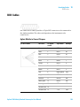
Table 2
Injection-Valve Technical Data
Autosampler
Motor type
4 V, 1.2 A stepper motor
Seal material
PEEK
Stator material
None
Number of ports
6
Switching time
< 150 ms
Agilent 1260 Infinity Standard Autosampler User Manual
17
1
Introduction to the Autosampler (ALS)
Introduction to the Autosampler (ALS)
Transport Assembly
The transport unit comprises an X-axis slide (left-right motion), a Z-axis arm
(up-down motion), and a gripper assembly (rotation and vial-gripping).
Mbdidg
I]ZiVbdidg
<g^eeZgbdidg
MVm^h
<g^eeZg
I]ZiVVm^h
OVm^h
Obdidg
;aZmWdVgY
Figure 7
Transport Assembly
The transport assembly uses four stepper motors driven in closed-loop mode
for accurate positioning of the gripper assembly. The rotational movement of
the motors is converted to linear motion (X- and Z-axes) by toothed belts
connected to the drive spindles. The rotation (theta axes) of the gripper
assembly is transferred from the motor by a toothed belt and series of gears.
The opening and closing of the gripper fingers are driven by a stepper motor
linked by a toothed belt to the planetary gearing inside the gripper assembly.
18
Agilent 1260 Infinity Standard Autosampler User Manual
Introduction to the Autosampler (ALS)
Introduction to the Autosampler (ALS)
1
The stepper motor positions are determined by the optical encoders mounted
onto the stepper-motor housing. The encoders monitor the position of the
motors continually, and correct for position errors automatically (e.g. if the
gripper is accidentally moved out of position when loading vials into the vial
tray). The initialization positions of the moving components are sensed by
reflection sensors mounted on the flex board. These positions are used by the
processor to calculate the actual motor position. An additional six reflection
sensors for tray recognition are mounted on the flex board at the front of the
assembly.
Agilent 1260 Infinity Standard Autosampler User Manual
19
1
20
Introduction to the Autosampler (ALS)
Introduction to the Autosampler (ALS)
Agilent 1260 Infinity Standard Autosampler User Manual
Agilent 1260 Infinity Standard Autosampler User Manual
2
Site Requirements and Specifications
Site Requirements
22
Physical Specifications
25
Performance Specifications Standard Autosampler
26
This chapter provides information on environmental requirements, physical and
performance specifications.
Agilent Technologies
21
2
Site Requirements and Specifications
Site Requirements
Site Requirements
Site Requirements
A suitable environment is important to ensure optimum performance of the
instrument.
Power Consideration
The autosampler power supply has wide-ranging capability (see Table 3 on
page 25). Consequently there is no voltage selector in the rear of the
autosampler. There are also no externally accessible fuses, because automatic
electronic fuses are implemented in the power supply.
The thermostatted autosampler comprises two modules, the standard
autosampler and the thermostat (G1330B). Both modules have a separate
power supply and a power plug for the line connections. The two modules are
connected by a control cable and both are turned on by the autosampler
module.
CAUTION
Damaged electronics
Disconnecting or reconnecting the sampler to thermostat cable when the power cords
are connected to either of the two modules will damage the electronics of the modules.
➔ Make sure the power cords are unplugged before disconnecting or reconnecting the
sampler to thermostat cable.
WA R N I N G
Hazard of electrical shock or damage of your instrumentation
can result, if the devices are connected to a line voltage higher than specified.
➔ Connect your instrument to the specified line voltage only.
22
Agilent 1260 Infinity Standard Autosampler User Manual
2
Site Requirements and Specifications
Site Requirements
CAUTION
Inaccessible power plug.
In case of emergency it must be possible to disconnect the instrument from the power
line at any time.
➔ Make sure the power connector of the instrument can be easily reached and
unplugged.
➔ Provide sufficient space behind the power socket of the instrument to unplug the
cable.
Power Cords
Different power cords are offered as options with the module. The female end
of all power cords is identical. It plugs into the power-input socket at the rear.
The male end of each power cord is different and designed to match the wall
socket of a particular country or region.
WA R N I N G
Absence of ground connection or use of unspecified power cord
The absence of ground connection or the use of unspecified power cord can lead to
electric shock or short circuit.
➔ Never operate your instrumentation from a power outlet that has no ground
connection.
➔ Never use a power cord other than the Agilent Technologies power cord designed
for your region.
WA R N I N G
Use of unsupplied cables
Using cables not supplied by Agilent Technologies can lead to damage of the
electronic components or personal injury.
➔ Never use cables other than the ones supplied by Agilent Technologies to ensure
proper functionality and compliance with safety or EMC regulations.
Agilent 1260 Infinity Standard Autosampler User Manual
23
2
Site Requirements and Specifications
Site Requirements
WA R N I N G
Unintended use of supplied power cords
Using power cords for unintended purposes can lead to personal injury or damage of
electronic equipment.
➔ Never use the power cords that Agilent Technologies supplies with this instrument
for any other equipment.
Bench Space
The autosampler can be placed on almost any laboratory bench (for
dimensions and weight see Table 3 on page 25). The instrument requires an
additional 2.5 cm (1.0 inch) of space on either side, and approximately 8 cm
(3.1 inch) at the rear for the circulation of air, and room for electrical
connections. Ensure the autosampler is installed in a horizontal position.
If a complete Agilent 1200 Infinity Series LC is to be installed on the bench,
make sure that the bench is designed to carry the weight of all the modules.
For a complete system including the thermostatted autosampler it is
recommended to position the modules in two stacks, see “Optimizing the Stack
Configuration” on page 29. Make sure that in this configuration there is 25 cm
(10 inch) space on either side of the thermostatted autosampler for the
circulation of air.
Condensation
CAUTION
Condensation within the module
Condensation will damage the system electronics.
➔ Do not store, ship or use your module under conditions where temperature
fluctuations could cause condensation within the module.
➔ If your module was shipped in cold weather, leave it in its box and allow it to warm
slowly to room temperature to avoid condensation.
24
Agilent 1260 Infinity Standard Autosampler User Manual
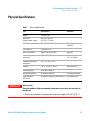
2
Site Requirements and Specifications
Physical Specifications
Physical Specifications
Table 3
WA R N I N G
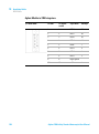
Physical Specifications
Type
Specification
Comments
Weight
14.2 kg (32 lbs)
Dimensions
(height × width × depth)
200 × 345 × 435 mm
(8 × 13.5 × 17 inches)
Line voltage
100 – 240 VAC, ± 10 %
Line frequency
50 or 60 Hz, ± 5 %
Power consumption
300 VA / 200 W / 683 BTU
Maximum
Ambient operating
temperature
0–55 °C (32–131 °F)
See warning “Hot rear
panel” on page 25
Ambient non-operating
temperature
-40 – 70 °C (-40 – 158 °F)
Humidity
< 95 % r.h. at 40 °C (104 °F)
Operating altitude
Up to 2000 m (6562 ft)
Non-operating altitude
Up to 4600 m (15091 ft)
For storing the module
Safety standards:
IEC, CSA, UL
Installation category II, Pollution degree 2
For indoor use only.
Wide-ranging
capability
Non-condensing
Hot rear panel
Using the module at high environmental temperatures may cause the rear panel to
become hot.
➔ Do not use the module at environmental temperatures higher than 50 °C (122 °F)
Agilent 1260 Infinity Standard Autosampler User Manual
25
2
Site Requirements and Specifications
Performance Specifications Standard Autosampler
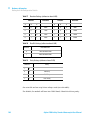
Performance Specifications Standard Autosampler
Table 4
26
Performance Specifications Agilent 1260 Infinity Standard Autosampler
(G1329B)
Type
Specification
Pressure
Operating range 0 - 60 MPa (0 - 600 bar, 0 - 8850 psi)
GLP features
Early maintenance feedback (EMF), electronic records of maintenance and
errors
Communications
Controller-area network (CAN), RS232C, APG-remote standard, optional
four external contact closures and BCD vial number output
Safety features
Leak detection and safe leak handling, low voltages in maintenance areas,
error detection and display
Injection range
0.1 - 100 µL in 0.1 µL increments (recommended 1 µL increments)
Up to 1500 µL with multiple draw (hardware modification required)
Replicate injections
1 – 99 from one vial
Precision
Typically < 0.25 % RSD of peak areas from < 5 µL to 100 µL
Typically < 1 % RSD of peak areas from 1 µL to 5 µL
Minimum sample
volume
1 µL from 5 µL sample in 100 µL microvial, or 1 µL from 10 µL sample in
300 µL microvial
Carryover
Typically < 0.1 %, < 0.05 % with external needle cleaning
Sample viscosity
range
0.2 – 50 cp
Sample capacity
100 × 2 mL vials in 1 tray
40 × 2 mL vials in ½ tray
15 × 6 mL vials in ½ tray (Agilent vials only)
Injection cycle time
50 s for draw speed 200 µL/min, ejection speed 200 µL/min, injection
volume 5 µL
Metering device
Metering pump in high pressure flow path
Agilent 1260 Infinity Standard Autosampler User Manual
Agilent 1260 Infinity Standard Autosampler User Manual
3
Installing the Autosampler
Unpacking the Autosampler
28
Optimizing the Stack Configuration
Installing the Autosampler
Flow Connections
29
32
35
Installing the Sample Tray
37
Transporting the Autosampler
38
This chapter provides information on unpacking, checking on completeness,
stack considerations and installation of the module.
Agilent Technologies
27
3
Installing the Autosampler
Unpacking the Autosampler
Unpacking the Autosampler
Damaged Packaging
If the delivery packaging shows signs of external damage, please call your
Agilent Technologies sales and service office immediately. Inform your service
representative that the instrument may have been damaged during shipment.
CAUTION
"Defective on arrival" problems
If there are signs of damage, please do not attempt to install the module. Inspection by
Agilent is required to evaluate if the instrument is in good condition or damaged.
➔ Notify your Agilent sales and service office about the damage.
➔ An Agilent service representative will inspect the instrument at your site and
initiate appropriate actions.
Delivery Checklist
Ensure all parts and materials have been delivered with your module. The
delivery checklist is shown below.
For parts identification please check the illustrated parts breakdown in “Parts
and Materials for Maintenance” on page 129.
Please report any missing or damaged parts to your local Agilent Technologies
sales and service office.
Table 5
28
Agilent 1260 Infintity Standard Autosampler
Description
Quantity
Autosampler
1
Power Cable
1
User Documentation DVD
1
Agilent 1260 Infinity Standard Autosampler User Manual
Installing the Autosampler
Optimizing the Stack Configuration
3
Optimizing the Stack Configuration
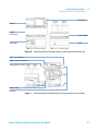
If your autosampler is part of a system, you can ensure optimum performance
by installing the autosampler in the stack in the position shown in Figure 8 on
page 29 and Figure 9 on page 30. Figure 10 on page 31 and Figure 11 on
page 31 show the configuration recommended for a thermostatted
autosampler. These configurations optimize the system flow path, ensuring
minimum delay volume.
HdakZciXVW^cZi
Ejbe
>chiVciE^adi
6jidhVbeaZg
8dajbcXdbeVgibZci
9ZiZXidg
Figure 8
Recommended Stack Configuration for an Autosampler (Front View)
Agilent 1260 Infinity Standard Autosampler User Manual
29
3
Installing the Autosampler
Optimizing the Stack Configuration
86C7jhXVWaZid
>chiVciE^adi
68edlZg
86C7jhXVWaZ
6cVad\h^\cVaidgZXdgYZg
Figure 9
30
A6CidA89ViV
HnhiZb
Recommended Stack Configuration for an Autosampler (Rear View)
Agilent 1260 Infinity Standard Autosampler User Manual
3
Installing the Autosampler
Optimizing the Stack Configuration
>chiVciE^adi
9ZiZXidg
8dajbc
XdbeVgibZci
HdakZciXVW^cZi
6jidhVbeaZg
Ejbe
Figure 10
Recommended Stack Configuration for a thermostatted ALS (Front View)
A6CidXdcigdahd[ilVgZ
86CWjhXVWaZid>chiVciE^adi
6cVad\h^\cVaidgZXdgYZg
68EdlZg
86CWjhXVWaZ
68EdlZg
Figure 11
Recommended Stack Configuration for a thermostatted ALS (Rear View)
Agilent 1260 Infinity Standard Autosampler User Manual
31
3
Installing the Autosampler
Installing the Autosampler
Installing the Autosampler
Parts required
#
Description
1
Sampler
1
Power cord
Software required
Agilent Data System and/or Instant Pilot G4208A.
Preparations
•
•
•
WA R N I N G
Locate bench space
Provide power connection
Unpack the Sampler
Module is partially energized when switched off, as long as the power cord is
plugged in.
Risk of stroke and other personal injury. Repair work at the module can lead to
personal injuries, e. g. shock hazard, when the module cover is opened and the
instrument is connected to power.
➔ Never perform any adjustment, maintenance or repair of the module with the top
cover removed and with the power cord plugged in.
➔ The security lever at the power input socket prevents that the module cover is taken
off when line power is still connected. Never plug the power line back in when cover
is removed.
WA R N I N G
Personal injury
To avoid personal injury, keep fingers away from the needle area during autosampler
operation.
➔ Do not bend the safety flap away from its position, or attempt to remove the safety
cover.
➔ Do not attempt to insert or remove a vial from the gripper when the gripper is
positioned below the needle.
32
Agilent 1260 Infinity Standard Autosampler User Manual
3
Installing the Autosampler
Installing the Autosampler
CAUTION
"Defective on arrival" problems
If there are signs of damage, please do not attempt to install the module. Inspection by
Agilent is required to evaluate if the instrument is in good condition or damaged.
➔ Notify your Agilent sales and service office about the damage.
➔ An Agilent service representative will inspect the instrument at your site and
initiate appropriate actions.
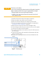
1 Install the LAN interface board in the sampler (if required).
2 Remove the adhesive tape which covers the front door.
3 Remove the front door and remove the transport protection foam.
4 Place the Autosampler on the bench or in the stack as recommended in
“Optimizing the Stack Configuration” on page 29.
5 Ensure the power switch at the front of the Autosampler is OFF.
6 Connect the power cable to the power connector at the rear of the sampler.
7 Connect the CAN cable to the other modules.
8 If an Agilent ChemStation is the controller, connect the LAN connector to
the LAN interface.
9 Connect the APG remote cable (optional) for all instruments other than
Agilent 1200 Infinity Series.
10 Turn ON power by pushing the button at the lower left hand side of the
sampler.
K^VacjbWZgdjieji
GZbdiZ
GH'('8
86C"Wjh
GZaVnXdciVXih
Figure 12
Cable Connections
Agilent 1260 Infinity Standard Autosampler User Manual
33
3
34
Installing the Autosampler
Installing the Autosampler
NOTE
If the front cover is not installed the autosampler is in a not ready condition and operation is
inhibited.
NOTE
The sampler is turned ON when the line power switch is pressed and the green indicator
lamp is illuminated. The detector is turned OFF when the line power switch is protruding
and the green light is OFF.
Agilent 1260 Infinity Standard Autosampler User Manual
Installing the Autosampler
Flow Connections
3
Flow Connections
Tools required
Description
Parts from the HPLC Tool-Kit
Parts required
Description
Parts from the Accessory kit
Preparations
WA R N I N G
•
Sampler is installed in the LC system
Toxic, flammable and hazardous solvents, samples and reagents
The handling of solvents, samples and reagents can hold health and safety risks.
➔ When working with these substances observe appropriate safety procedures (for
example by wearing goggles, safety gloves and protective clothing) as described in
the material handling and safety data sheet supplied by the vendor, and follow good
laboratory practice.
➔ The volume of substances should be reduced to the minimum required for the
analysis.
➔ Do not operate the instrument in an explosive atmosphere.
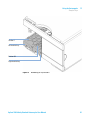
1 Connect the pump outlet capillary to port 1 of the injection valve.
2 Connect column-compartment inlet capillary to port 6 of the injection
valve.
3 Connect the corrugated waste tube to the solvent waste from the leak plane.
4 Ensure that the waste tube is positioned inside the leak channel.
NOTE
Do not extend the waste capillary of the autosampler. The siphoning effect might empty the
complete seat capillary introducing air into the system.
Agilent 1260 Infinity Standard Autosampler User Manual
35
3
Installing the Autosampler
Flow Connections
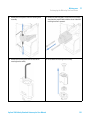
8dajbcXdbeVgibZci
^caZiXVe^aaVgn
EjbedjiaZiXVe^aaVgn
HdakZcilVhiZ[dgXdggj\ViZYijWZ
LVhiZijW^caZV`X]VccZa
Figure 13
36
Hydraulic Connections
Agilent 1260 Infinity Standard Autosampler User Manual
Installing the Autosampler
Installing the Sample Tray
3
Installing the Sample Tray
1 Open the front door.
2 Load the sample tray with sample vials as required.
3 Slide the sample tray into the autosampler so that the rear of the sample
tray is seated firmly against the rear of the sample-tray area.
4 Press the front of the sample tray down to secure the tray in the
autosampler.
NOTE
If the thermostatted autosampler tray pops out of position the air channel adapter is not
inserted correctly.
Figure 14
Installing the Sample Tray
Agilent 1260 Infinity Standard Autosampler User Manual
37
3
Installing the Autosampler
Transporting the Autosampler
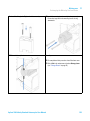
Transporting the Autosampler
When moving the autosampler around the laboratory, no special precautions
are needed. However, if the autosampler needs to be shipped to another
location via carrier, ensure:
• The transport assembly is parked, see “Park Arm” on page 63;
• The vial tray is secured.
If the autosampler is to be shipped to another location, the transport assembly
must be moved to the park position to prevent mechanical damage should the
shipping container be subjected to excessive shock. Also, ensure the vial tray
is secured in place with suitable packaging, otherwise the tray may become
loose and damage internal components.
38
Agilent 1260 Infinity Standard Autosampler User Manual
Agilent 1260 Infinity Standard Autosampler User Manual
4
Using the Autosampler
Sample Trays
40
Choice of Vials and Caps
42
This chapter provides information on how to set up the module for an analysis
and explains the basic settings.
Agilent Technologies
39
4
Using the Autosampler
Sample Trays
Sample Trays
Supported trays for the module:
p/n
Description
G1313-44510
Tray for 100 x 2 mL vials
G1313-44513
Halftray for 15 x 6 mL vials
G1313-44512
Halftray for 40 x 2 mL vials
G1329-60011
Thermostattable tray for 100 x 2 mL vials
Half-Tray Combinations
Half-trays can be installed in any combination enabling both 2 mL-and
6 mL-vials to be used simultaneously.
Numbering of Vial Positions
The standard 100-vial tray has vial positions 1 to 100. However, when using
two half-trays, the numbering convention is slightly different. The vial
positions of the right-hand half tray begin at position 101 as follows:
Left-hand 40-position tray: 1 - 40
Left-hand 15-position tray: 1–15
Right-hand 40-position tray: 101–140
Right-hand 15-position tray: 101–115
40
Agilent 1260 Infinity Standard Autosampler User Manual
Using the Autosampler
Sample Trays
4
Edh^i^dc&
AZ[i]VcY]Va[igVn
Edh^i^dc&%&
G^\]i]VcY]Va[igVn
Figure 15
Numbering of Tray Positions
Agilent 1260 Infinity Standard Autosampler User Manual
41
4
Using the Autosampler
Choice of Vials and Caps
Choice of Vials and Caps
List of Compatible Vials and Caps
For reliable operation vials used with the autosampler must not have tapered
shoulders or caps that are wider than the body of the vial. The vials in “Crimp
Top Vials” on page 42, “Snap Top Vials” on page 43 and “Screw Top Vials” on
page 43 and caps in “Crimp Caps” on page 44, “Snap Caps” on page 44 and
“Screw Caps” on page 44 (shown with their Part numbers) have been
successfully tested using a minimum of 15,000 injections with the
autosampler.
Crimp Top Vials
42
p/n
Description
5181-3375
Crimp Top Vial, 2 mL, clear glass, 100/Pack
5183-4491
Crimp Top Vial, 2 mL, clear glass, 1000/Pack
5182-0543
Crimp Top Vial, 2 mL, clear glass, write-on spot, 100/Pack
5183-4492
Crimp Top Vial, 2 mL, clear glass, write-on spot, 1000/Pack
5183-4494
Crimp Top Vial, 2 mL, clear glass, write-on spot, 100/Pack (silanized)
5181-3376
Crimp Top Vial, 2 mL, amber glass, write-on spot, 100/Pack
5183-4493
Crimp Top Vial, 2 mL, amber glass, write-on spot, 1000/Pack
5183-4495
Crimp Top Vial, 2 mL, amber glass, write-on spot, 100/Pack (silanized)
5182-0567
Crimp Top Vial, 1 mL, polypropylene, wide opening, 100/Pack
5183-4496
Crimp Top Vial, 1 mL, polypropylene, wide opening, 100/Pack (silanized)
9301-0978
crimp top vial, 0.3 mL, polypropylene, wide opening, 1000/pack
Agilent 1260 Infinity Standard Autosampler User Manual
4
Using the Autosampler
Choice of Vials and Caps
Snap Top Vials
p/n
Description
5182-0544
Snap Top Vial, 2 mL, clear glass, 100/Pack
5183-4504
Snap Top Vial, 2 mL, clear glass, 1000/Pack
5183-4507
Snap Top Vial, 2 mL, clear glass, 100/Pack (silanized)
5182-0546
Snap Top Vial, 2 mL, clear glass, write-on spot, 100/Pack
5183-4505
Snap Top Vial, 2 mL, clear glass, write-on spot, 1000/Pack
5183-4508
Snap Top Vial, 2 mL, clear glass, write-on spot, 100/Pack (silanized)
5182-0545
Snap Top Vial, 2 mL, amber glass, write-on spot, 100/Pack
5183-4506
Snap Top Vial, 2 mL, amber glass, write-on spot, 1000/Pack
5183-4509
Snap Top Vial, 2 mL, amber glass, write-on spot, 100/Pack (silanized)
Screw Top Vials
p/n
Description
5182-0714
Screw Cap Vials, 2 mL, clear glass, 100/Pack
5183-2067
Screw Top Vial, 2 mL, clear glass, 1000/Pack
5183-2070
Screw Top Vial, 2 mL, clear glass, 100/Pack (silanized)
5182-0715
Screw Top Vial, 2 mL, clear glass, write-on spot, 100/Pack
5183-2068
Screw Top Vial, 2 mL, clear glass, write-on spot, 1000/Pack
5183-2071
Screw Top Vial, 2 mL, clear glass, write-on spot, 100/Pack (silanized)
5182-0716
Screw Cap Vial, 2 mL, amber glass, write-on spot, 100/pk
5183-2069
Screw Top Vial, 2 mL, amber glass, write-on spot, 1000/Pack
5183-2072
Screw Top Vial, 2 mL, amber glass, write-on spot, 100/Pack (silanized)
Agilent 1260 Infinity Standard Autosampler User Manual
43
4
Using the Autosampler
Choice of Vials and Caps
Crimp Caps
p/n
Description
5181-1210
Crimp Cap, silver aluminum, septum (clear PTFE/red rubber), 100/Pack
5183-4498
Crimp Cap, silver aluminum, septum (clear PTFE/red rubber), 1000/Pack
5181-1215
Crimp Cap, blue aluminum, septum (clear PTFE/red rubber), 100/Pack
5181-1216
Crimp Cap, green aluminum, septum (clear PTFE/red rubber), 100/Pack
5181-1217
Crimp Cap, red aluminum, septum (clear PTFE/red rubber), 100/Pack
Snap Caps
p/n
Description
5182-0550
Snap Cap, clear polypropylene, septum (clear PTFE/red rubber), 100/Pack
5182-3458
Snap Cap, blue polypropylene, septum (clear PTFE/red rubber), 100/Pack
5182-3457
Snap Cap, green polypropylene, septum (clear PTFE/red rubber), 100/Pack
5182-3459
Snap Cap, red polypropylene, septum (clear PTFE/red rubber), 100/Pack
Screw Caps
44
p/n
Description
5182-0717
Screw Cap, blue polypropylene, septum (clear PTFE/red rubber), 100/Pack
5182-0718
Screw Cap, green polypropylene, septum (clear PTFE/red rubber), 100/Pack
5182-0719
Screw Cap, red polypropylene, septum (clear PTFE/red rubber), 100/Pack
5182-0720
Screw Cap, blue polypropylene, septum (clear PTFE/silicone), 100/Pack
5182-0721
Screw Cap, green polypropylene, septum (clear PTFE/silicone), 100/Pack
5182-0722
Screw Cap, red polypropylene, septum (clear PTFE/silicone), 100/Pack
Agilent 1260 Infinity Standard Autosampler User Manual
Agilent 1260 Infinity Standard Autosampler User Manual
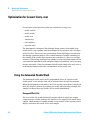
5
Optimizing Performance
Optimization for Lowest Carry-over 46
Using the Automated Needle Wash 46
Using an Injector Program 47
General Recommendation to Lowest Carry-over
48
Fast Injection Cycle and Low Delay Volume 49
Overlapped Injection Mode 49
General Recommendations for Fast Injection Cycle Times
50
Precise Injection Volume 51
Draw and Eject Speed 51
Choice of Rotor Seal
53
This chapter provides information on how to optimize the module.
Agilent Technologies
45
5
Optimizing Performance
Optimization for Lowest Carry-over
Optimization for Lowest Carry-over
Several parts of an injection system can contribute to carry-over:
• needle outside
• needle inside
• needle seat
• sample loop
• seat capillary
• injection valve
The autosampler continuous flow-through design ensures that sample loop,
needle inside, seat capillary, and the mainpass of the injection valve is always
in the flow line. These parts are continuously flushed during an isocratic and
also during a gradient analysis. The residual amount of sample remaining on
the outside of the needle after injection may contribute to carry-over in some
instances. When using small injection volumes or when injecting samples of low
concentration immediately after samples of high concentration, carry-over may
become noticeable. Using the automated needle wash enables the carry-over to
be minimized and prevents also contamination of the needle seat.
Using the Automated Needle Wash
The automated needle wash can be programmed either as “injection with
needle wash” or the needle wash can be included into the injector program.
When the automated needle wash is used, the needle is moved into a wash vial
after the sample is drawn. By washing the needle after drawing a sample, the
sample is removed from the surface of the needle immediately.
Uncapped Wash Vial
For best results, the wash vial should contain solvent in which the sample
components are soluble, and the vial should not be capped. If the wash vial is
capped, small amounts of sample remain on the surface of the septum, which
may be carried on the needle to the next sample.
46
Agilent 1260 Infinity Standard Autosampler User Manual
Optimizing Performance
Optimization for Lowest Carry-over
5
Injector Program with Needle Wash
The injector program includes the command NEEDLE WASH. When this
command is included in the injector program, the needle is lowered once into
the specified wash vial before injection.
For example:
1 DRAW 5 μl
2 NEEDLE WASH vial 7
3 INJECT
Line 1 draws 5 μl from the current sample vial. Line 2 moves the needle to
vial 7. Line 3 injects the sample (valve switches to main pass).
Using an Injector Program
The process is based on a program that switches the bypass grove of the
injection valve into the flow line for cleaning. This switching event is
performed at the end of the equilibration time to ensure that the bypass grove
is filled with the start concentration of the mobile phase. Otherwise the
separation could be influenced, especially if microbore columns are used.
For example:
Outside wash of needle in vial 7 before injection
Injector program:
Draw x.x (y) μl from sample
NEEDLE WASH vial 7
Inject
Wait (equilibration time - see text above)
Valve bypass
Wait 0.2 min
Valve mainpass
Valve bypass
Valve mainpass
NOTE
Overlapped injection together with additional injection valve switching is not possible.
Agilent 1260 Infinity Standard Autosampler User Manual
47
5
Optimizing Performance
Optimization for Lowest Carry-over
General Recommendation to Lowest Carry-over
• For samples where needle outside cannot be cleaned sufficiently with water
or alcohol use wash vials with an appropriate solvent. Using an injector
program and several wash vials can be used for cleaning.
In case the needle seat has got contaminated and carry-over is significantly
higher than expected, the following procedure can be used to clean the needle
seat:
• Go to MORE INJECTOR and set needle to home position.
• Pipette an appropriate solvent on to the needle seat. The solvent should be
able to dissolve the contamination. If this is not known use 2 or 3 solvents
of different polarity. Use several milliliters to clean the seat.
• Clean the needle seat with a tissue and remove all liquid from it.
• RESET the injector.
48
Agilent 1260 Infinity Standard Autosampler User Manual
5
Optimizing Performance
Fast Injection Cycle and Low Delay Volume
Fast Injection Cycle and Low Delay Volume
Short injection cycle times for high sample througput is one of the most
important requirements in analytical laboratories. In order to shorten cycle
times, you can:
• shorten the column length
• use high flow rates
• apply a steep gradient
Having optimized these parameters, further reduction of cycle times can be
obtained using the overlapped injection mode.
Overlapped Injection Mode
In this process, as soon as the sample has reached the column, the injection
valve is switched back to bypass and the next injection cycle starts but waits
with switching to mainpass until the actual run is finished. You gain the
sample preparation time when using this process.
Switching the valve into the bypass position reduces the system delay volume,
the mobile phase is directed to the column without passing sample loop,
needle and needle seat capillary. This can help to have faster cycle times
especially if low flow rates have to be used like it is mandatory in narrow bore
and micro bore HPLC.
NOTE
Having the valve in bypass position can increase the carry-over in the system.
The injection cycle times also depend on the injection volume. In identically
standard condition, injecting 100 μl instead of 1 μl, increase the injection time
by approximately 8 sec. In this case and if the viscosity of the sample allows it,
the draw and eject speed of the injection system has to be increased.
Agilent 1260 Infinity Standard Autosampler User Manual
49
5
Optimizing Performance
Fast Injection Cycle and Low Delay Volume
NOTE
For the last injection of the sequence with overlapped injections it has to be considered
that for this run the injection valve is not switched as for the previous runs and
consequently the injector delay volume is not bypassed. This means the retention times are
prolonged for the last run. Especially at low flow rates this can lead to retention time
changes which are too big for the actual calibration table. To overcome this it is
recommended to add an additional “blank” injection as last injection to the sequence.
General Recommendations for Fast Injection Cycle Times
As described in this section, the first step to provide short cycle times are
optimizing the chromatographic conditions. If this is done the autosampler
parameter should be set to:
• Overlapped injection mode
• Increase of draw and eject speed for large injection volumes
• Add at last run a blank, if overlapped injection is used
To reduce the injection time, the detector balance has to be set to OFF.
50
Agilent 1260 Infinity Standard Autosampler User Manual
Optimizing Performance
Precise Injection Volume
5
Precise Injection Volume
Injection Volumes Less Than 2 µL
When the injection valve switches to the BYPASS position, the mobile phase in
the sample loop is depressurized. When the syringe begins drawing sample,
the pressureof the mobile phase is decreased further. If the mobile phase is
not degassed adequately, small gas bubbles may form in the sample loop
during the injection sequence. When using injection volumes < 2 μL, these gas
bubbles may affect the injection-volume precision. For best injection-volume
precision with injection volumes < 2 μL, use of an Agilent 1260 Infinity
degasser is recommended to ensure the mobile phase is adequately degassed.
Also, using the automated needle wash (see “Optimization for Lowest
Carry-over” on page 46) between injections reduces carry-over to a minimum,
further improving the injection volume precision.
Draw and Eject Speed
Draw Speed
The speed at which the metering unit draws sample out of the vial may have an
influence on the injection volume precision when using viscous samples. If the
draw speed is too high, air bubbles may form in the sample plug, affecting
precision. The default draw speed is 200 μL/min. This speed is suitable for the
majority of applications, however, when using viscous samples, set the draw
speed to lower speed for optimum results. A DRAW statement in an injector
program also uses the draw speed setting which is configured for the
autosampler.
Agilent 1260 Infinity Standard Autosampler User Manual
51
5
Optimizing Performance
Precise Injection Volume
Eject Speed
The default eject speed setting is 200 μL/min. When using large injection
volumes, setting the eject speed to a higher value speeds up the injection cycle
by shortening the time the metering unit requires to eject solvent at the
beginning of the injection cycle (when the piston returns to the home
position).
An EJECT statement in an injector program also uses the eject speed setting
which is configured for the autosampler. A faster eject speed shortens the time
required to run the injector program. When using viscous samples, a high eject
speed should be avoided.
52
Agilent 1260 Infinity Standard Autosampler User Manual
Optimizing Performance
Choice of Rotor Seal
5
Choice of Rotor Seal
Vespel™ Seal (for standard valves only)
The standard seal has sealing material made of Vespel. Vespel is suitable for
applications using mobile phases within the pH range of 2.3 to 9.5, which is
suitable for the majority of applications. However, for applications using
mobile phases with pH below 2.3 or above 9.5, the Vespel seal may degrade
faster, leading to reduced seal lifetime.
Tefzel™ Seal (for standard valve only)
For mobile phases with pH below 2.3 or above 9.5, or for conditions where the
lifetime of the Vespel seal is drastically reduced, a seal made of Tefzel is
available. Tefzel is more resistant than Vespel to extremes of pH, however, is a
slightly softer material. Under normal conditions, the expected lifetime of the
Tefzel seal is shorter than the Vespel seal, however, Tefzel may have the longer
lifetime under more extreme mobile phase conditions.
PEEK Seal (for preparative injection valve only)
The preparative injection valve has a sealing material made of PEEK. This
material has high chemical resistance and versatility. It is suitable for
application using mobile phases within a pH between 1 and 14.
This seal is also used for the G1329B module.
NOTE
Strong oxidizing acids such as concentrated nitric and sulfuric acids are not compatible
with PEEK.
Agilent 1260 Infinity Standard Autosampler User Manual
53
5
54
Optimizing Performance
Choice of Rotor Seal
Agilent 1260 Infinity Standard Autosampler User Manual
Agilent 1260 Infinity Standard Autosampler User Manual
6
Troubleshooting and Diagnostics
Overview of the Module’s Indicators and Test Functions
56
Status Indicators 57
Power Supply Indicator 57
Module Status Indicator 58
Maintenance Functions 59
User Interface 59
Change Needle 60
Change Piston 62
Park Arm 63
Change Gripper 65
Tray Alignment 65
ALS Step Commands
Troubleshooting
66
68
Troubleshooting Guide for the Sample Transport Assembly 70
Intermittent lock-ups with or without vial in the gripper fingers 71
Jittery (shaky) movement in X and/or theta axes and/or when the
needle goes through the gripper arm into the vial 73
Poor alignment 75
Agilent Lab Advisor Software
77
Overview about the troubleshooting and diagnostic features.
Agilent Technologies
55
6
Troubleshooting and Diagnostics
Overview of the Module’s Indicators and Test Functions
Overview of the Module’s Indicators and Test Functions
Status Indicators
The module is provided with two status indicators which indicate the
operational state (prerun, run, and error states) of the module. The status
indicators provide a quick visual check of the operation of the module.
Error Messages
In the event of an electronic, mechanical or hydraulic failure, the module
generates an error message in the user interface. For each message, a short
description of the failure, a list of probable causes of the problem, and a list of
suggested actions to fix the problem are provided (see chapter Error Information).
Maintenance Functions
The maintenance functions position the needle arm, gripper assembly, and
metering device for easy access when doing maintenance (see “Maintenance
Functions” on page 59).
Tray Alignment
Tray alignment is required after repair of internal components, or after a firmware
update. The procedure aligns the gripper arm correctly to ensure the positioning
of the gripper arm is correct for all vials (see “Tray Alignment” on page 65).
Step Commands
The step functions provide the possibility to execute each step of the sampling
sequence individually. The step functions are used primarily for
troubleshooting, and for verification of correct autosampler operation after
repair (see “ALS Step Commands” on page 66).
56
Agilent 1260 Infinity Standard Autosampler User Manual
Troubleshooting and Diagnostics
Status Indicators
6
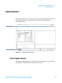
Status Indicators
Two status indicators are located on the front of the autosampler. The lower
left indicates the power supply status, the upper right indicates the
autosampler status.
HiVijh^cY^XVidg
EdlZghjeean^cY^XVidg
Figure 16
Location of Status Indicators
Power Supply Indicator
The power supply indicator is integrated into the main power switch. When
the indicator is illuminated (green) the power is ON.
Agilent 1260 Infinity Standard Autosampler User Manual
57
6
Troubleshooting and Diagnostics
Status Indicators
Module Status Indicator
The module status indicator indicates one of six possible module conditions:
• When the status indicator is OFF (and power switch light is on), the module
is in a prerun condition, and is ready to begin an analysis.
• A green status indicator, indicates the module is performing an analysis
(run mode).
• A yellow indicator indicates a not-ready condition. The module is in a
not-ready state when it is waiting for a specific condition to be reached or
completed (for example, immediately after changing a set point), or while a
self-test procedure is running.
• An error condition is indicated when the status indicator is red. An error
condition indicates the module has detected an internal problem which
affects correct operation of the module. Usually, an error condition requires
attention (e.g. leak, defective internal components). An error condition
always interrupts the analysis.
If the error occurs during analysis, it is propagated within the LC system,
i.e. a red LED may indicate a problem of a different module. Use the status
display of your user interface for finding the root cause/module of the
error.
• A blinking indicator indicates that the module is in resident mode (e.g.
during update of main firmware).
• A fast blinking indicator indicates that the module is in a low-level error
mode. In such a case try to re-boot the module or try a cold-start (see
“Special Settings” on page 169. Then try a firmware update (see “Replacing
the Module’s Firmware” on page 127). If this does not help, a main board
replacement is required.
58
Agilent 1260 Infinity Standard Autosampler User Manual
6
Troubleshooting and Diagnostics
Maintenance Functions
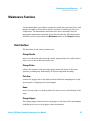
Maintenance Functions
Certain maintenance procedures require the needle arm, metering device, and
gripper assembly to be moved to specific positions to enable easy access to
components. The maintenance functions move these assemblies into the
appropriate maintenance position. In the Data System the ALS maintenance
positions can be selected from the Maintenance menu in the Diagnosis display.
User Interface
The functions for the control software are:
Change Needle:
moves the safety flap away from the needle, and positions the needle arm for
easy access to the needle and needle seat.
Change Piston:
relieves the tension on the metering spring (draws the piston to the outer
position), enabling easy disassembly of the metering head assembly).
Park Arm:
secures the gripper arm to the park position behind the sampling unit. ready
for transport or shipping of the autosampler.
Home:
moves the tray arm to its home position for better access and exchange of the
trays.
Change Gripper:
The change gripper function moves the gripper to the front of the autosampler
enabling easy access to the gripper release mechanism.
Agilent 1260 Infinity Standard Autosampler User Manual
59
6
Troubleshooting and Diagnostics
Maintenance Functions
Change Needle
WA R N I N G
For needle exchange, the needle arm moves down automatically when the front
cover is removed.
Risk of personal injury due to moving needle.
➔ Keep fingers away from the needle area during needle movement.
The change-needle/seat function moves the safety flap out of position, and
positions the needle for easy exchange and alignment of the needle and needle
seat.
User Interface
The commands for the Data System are:
NOTE
The autosampler front cover must be in place when Start and End are selected.
Start
Moves the safety flap away from the needle, and positions the needle
approximately 15 mm above the needle seat.
Needle Up
Press function key couple of times to move the needle arm up in 2 mm steps.
Needle Down
Press function key couple of times to move the needle arm down in 2 mm
steps. The lowest position (end position) is used to align the needle at the
correct position in the needle seat.
End
Completes the procedure by moving the gripper arm to the home position, and
releasing the safety flap.
60
Agilent 1260 Infinity Standard Autosampler User Manual
Troubleshooting and Diagnostics
Maintenance Functions
6
Using the Change Needle Function
1 Ensure the front cover is installed.
2 Select Start to move the needle arm to the maintenance position.
3 Remove the front cover.
NOTE
Do not remove the front cover until the needle arm is in its maintenance position. Removing
the cover while the needle arm is activated may lock up the system.
4 Exchange the needle or needle seat (see “Exchanging the Needle-Seat
Assembly” on page 114 and “Exchanging the Needle Assembly” on
page 111).
5 Replace the front cover.
6 Select End to complete the procedure.
Agilent 1260 Infinity Standard Autosampler User Manual
61
6
Troubleshooting and Diagnostics
Maintenance Functions
Change Piston
The change-piston function draws the piston away from the home position,
relieving the tension on the spring. In this position, the analytical head
assembly can be removed and reinstalled easily after maintenance.
User Interface
The commands for the control software are:
Start
Draws the piston away from the home position, relieving the tension on the
spring.
End
Repositions the piston at the home position.
Using the Change Seal Function
1 Select Start to move the piston to the maintenance position.
2 Exchange the metering seal (see “Exchanging the Gripper Arm” on
page 124).
3 Select End to move the piston back to the home position.
62
Agilent 1260 Infinity Standard Autosampler User Manual
Troubleshooting and Diagnostics
Maintenance Functions
6
Park Arm
User Interface
In the control software the Park Arm command is part of the ALS
maintenance positions that can be selected from the Maintenance menu in the
Diagnosis display.
The commands for the control software are:
Park Arm
moves the gripper arm to the park position.
Home
moves the gripper arm out of the park position to the home position.
Agilent 1260 Infinity Standard Autosampler User Manual
63
6
Troubleshooting and Diagnostics
Maintenance Functions
To prepare autosampler for transportation
The park arm function moves the gripper and transport slider to the home
position behind the sampling unit, and lowers the gripper arm into the park
position where the transport assembly is secured against a mechanical stop.
The autosampler can be switched OFF after parking the arm.
When
Before transporting or shipping the autosampler.
CAUTION
Unsecured Transportation of Autosampler
Unsecured transportation of the autosampler may result in mechanical damage to the
gripper and transport slider.
➔ Always secure the arm in the park position.
NOTE
Before parking the gripper arm, ensure there is no vial in the gripper. Use the Release
Gripper function to remove the vial.
1 Select Park Arm.
2 When the arm is in the park position, the autosampler is ready for
shipment, and can be switched OFF.
64
Agilent 1260 Infinity Standard Autosampler User Manual
6
Troubleshooting and Diagnostics
Maintenance Functions
Change Gripper
The change gripper function moves the gripper to the front of the autosampler
enabling easy access to the gripper release mechanism.
User Interface
The commands for the control software are:
Start
Moves the transport assembly and gripper arm to the position required to
change the gripper arm.
End
Repositions the transport assembly and gripper arm to the home position.
Using the Change Seal Function
1 Select Start to move the gripper arm to the maintenance position.
2 Exchange the gripper arm (see “Exchanging the Gripper Arm” on page 124).
3 Select End to move the gripper arm to the home position.
Tray Alignment
Tray alignment is required to compensate for small deviations in positioning
of the gripper which may occur after disassembling the module for repair.
The tray alignment procedure uses several tray positions as reference points.
Because the tray is a rectangle, a two-point alignment is sufficient to correct
all other vial positions within the tray. On completion of the procedure, the
corrected gripper positions are stored in the instrument firmware.
Agilent 1260 Infinity Standard Autosampler User Manual
65
6
Troubleshooting and Diagnostics
ALS Step Commands
ALS Step Commands
Each movement of the sampling sequence can be done under manual control.
This is useful during troubleshooting, where close observation of each of the
sampling steps is required to confirm a specific failure mode or verify
successful completion of a repair.
Each injector step command actually consists of a series of individual
commands that move the autosampler components to predefined positions,
enabling the specific step to be done.
Table 6
66
Injector step commands
Step
Action
Comments
Valve Bypass
Switches injection valve to
the bypass position.
Plunger Home
Moves the plunger to the
home position.
Needle Up
Lifts the needle arm to the
upper position.
Command also switches the valve to bypass if
it is not already in that position.
Vial to Seat
Moves the selected vial to
the seat position.
Command also lifts the needle to the upper
position.
Needle into
Sample
Lowers the needle into the
sample.
Command also positions the vial at the seat,
and lifts the needle to the upper position.
Draw
Metering device draws the
defined injection volume.
Command also positions the vial at the seat,
lifts the needle, and lowers the needle into
vial. Command can be done more than once
(maximum draw volume of 100 µL cannot be
exceeded). Use Plunger Home to reset the
metering device.
Needle Up
Lifts the needle out of the
vial.
Command also switches the valve to bypass if
it is not already in that position.
Vial to Tray
Returns the selected vial to
the tray position.
Command also lifts the needle to the upper
position.
Agilent 1260 Infinity Standard Autosampler User Manual
Troubleshooting and Diagnostics
ALS Step Commands
Table 6
6
Injector step commands
Step
Action
Comments
Needle into Seat
Lowers the needle arm into
the seat.
Command also returns the vial to the tray
position.
Valve Mainpass
Switches the injection valve
to the mainpass position.
Reset
Resets the injector.
Agilent 1260 Infinity Standard Autosampler User Manual
67
6
Troubleshooting and Diagnostics
Troubleshooting
Troubleshooting
If the autosampler is unable to perform a specific step due to a hardware
failure, an error message is generated. You can use the injector steps to do the
injection sequence, while observing how the instrument responds. Table 7 on
page 68 summarizes the injector steps, and lists the associated error messages
and probable causes of step failures.
Table 7
68
Step Failures
Step Function
Probable Failure Modes
Bypass
Valve already in bypass.
Valve not connected.
Defective injection valve.
Piston Home
Defective or dirty sensor on the sampling-unit flex board.
Defective metering-drive motor.
Needle Up
Needle already in the upper position.
Defective or dirty sensor on the sampling-unit flex board.
Sticking needle-arm assembly.
Defective needle-drive motor.
Vial to Seat
No vial in selected position.
Vial already in seat position.
Defective transport assembly motors.
Sticking transport assembly.
Defective gripper assembly.
Gripper not aligned (see “Tray Alignment” on page 65).
Draw
Sum of all draw volumes exceeds 100µl.
Defective metering-drive motor.
Needle Up
Needle already in the upper position.
Needle already in the upper position.
Defective or dirty sensor on the sampling-unit flex board.
Sticking needle-arm assembly.
Defective needle-drive motor.
Agilent 1260 Infinity Standard Autosampler User Manual
Troubleshooting and Diagnostics
Troubleshooting
Table 7
6
Step Failures
Step Function
Probable Failure Modes
Vial to Tray
Defective transport assembly motors.
Sticking transport assembly.
Defective gripper assembly.
Gripper not aligned (see “Tray Alignment” on page 65).
Needle Down
Needle already in the lower position.
Defective or dirty sensor on the sampling-unit flex board.
Sticking needle-arm assembly.
Defective needle-drive motor.
Mainpass
Valve already in mainpass.
Valve not connected.
Defective injection valve.
Needle Up/Mainpass
Blockage in the sample loop or needle (no solvent flow).
Needle already in the upper position.
Defective or dirty sensor on the sampling-unit flex board.
Sticking needle-arm assembly.
Defective needle-drive motor.
Valve already in mainpass.
Valve not connected.
Defective injection valve.
Agilent 1260 Infinity Standard Autosampler User Manual
69
6
Troubleshooting and Diagnostics
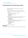
Troubleshooting Guide for the Sample Transport Assembly
Troubleshooting Guide for the Sample Transport Assembly
This troubleshooting guide is meant to help you diagnose and repair
autosampler problems.
In general, autosampler problems can be divided into three categories.
1 Intermittent lock-ups with or without vial in the gripper fingers with error
messages
Many times the sampler is being used very heavily.
• motor overtemp (0 or 1 or 2 or 3)
• movement failed (0 or 1 or 2 or 3)
• missing vial
2 Jittery (shaky) movement in X and/or theta axes and/or when the needle
goes through the gripper arm into the vial with error messages
• motor overtemp (0 or 2)
• movement failed (0 or 2)
3 Poor alignment, seen during vial pickup and vial replacement and/or when
the needle hits the gripper arm with error messages
• motor overtemp (0 or 2 or 3)
• movement failed (0 or 2 or 3)
• missing vial
NOTE
70
Motor 0=X; 1=Z; 2=Theta; 3=Gripper.
Agilent 1260 Infinity Standard Autosampler User Manual
6
Troubleshooting and Diagnostics
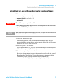
Troubleshooting Guide for the Sample Transport Assembly
Intermittent lock-ups with or without vial in the gripper fingers
With error messages
• motor overtemp (0 or 1 or 2 or 3)
• movement failed (0 or 1 or 2 or 3)
• missing vial
WA R N I N G
Personal damage, damage to the module
➔ Some of these procedures require a trained service engineer. Persons who are not
qualified MUST NOT perform these procedures.
NOTE
When a motor over temperature message has occurred, the sampler must be turned OFF for
about 10 minutes to allow the motor to cool down.
1 Check the vials and the caps.
For reliable operation, vials used with the autosampler must not have
tapered shoulders or caps that are wider than the body of the vial. For more
details see the service note G1313-017.
2 Very heavy usage - use a macro.
A pre-sequence macro, inj_rset.mac will automatically reset the sampler at
the start of a sequence (ChemStation).
3 Reset the sampler alignment to default value.
Reset tray alignment, and transport alignment is possible with the Control
Module and the ChemStation. To reset the transport alignment with the
ChemStation, enter following command in the command line.
Print sendmodule$(lals, “tray:alig 0.00,0.00”)
Agilent 1260 Infinity Standard Autosampler User Manual
71
6
Troubleshooting and Diagnostics
Troubleshooting Guide for the Sample Transport Assembly
4 Check the tension of the belts.
For this use the ALS Torque Verification in LabAdvisor and measure the torque
for each axis.
Table 8
Typical ranges
Theta (both) 30-50
X-axis (both) 50-90
Z-axis (both) 90-130
Gripper open 30-65
Gripper closed maximum 30
NOTE
If the Gripper open/closed torque is not in the range, proceed with step 5 on page 72. If the
theta or X torque is not in the range, proceed with step 6 on page 72 (if you think you can
adjust the torque), otherwise proceed with step 7 on page 72.
5 Exchange the gripper arm assembly (part number G1313-60010).
6 Adjust the belts tension.
• If the measured torque value is too low, the belt needs to be tightened.
• If the measured torque value is too high, the belt needs to be loosened.
For this, slide the motor (X or theta) on the holder bracket in the
appropriate direction and test the tension with the ALS Torque Verification in
LabAdvisor. Repeat this steps until the values are in the appropriate torque
range.
7 If these measures don't resolve the problem, it is necessary to exchange the
transport assembly or the main board. To do this, please contact your
Agilent service representative.
72
Agilent 1260 Infinity Standard Autosampler User Manual
6
Troubleshooting and Diagnostics
Troubleshooting Guide for the Sample Transport Assembly
Jittery (shaky) movement in X and/or theta axes and/or when the
needle goes through the gripper arm into the vial
With Error messages
• motor overtemp (0 or 2)
• movement failed (0 or 2)
WA R N I N G
Personal damage, damage to the module
➔ Some of these procedures require a trained service engineer. Persons who are not
qualified MUST NOT perform these procedures.
NOTE
When a motor over temperature message has occurred, the sampler must be turned OFF for
about 10 minutes to allow the motor to cool down.
1 Check the cleanliness of the transport rods (X-axis) and clean them.
NOTE
DO NOT lubricate the transport rod.
2 Lubricate the X-gear.
Friction can result in the belt slipping on the gear so that the position of the
belt teeth towards the gear changes.
To avoid this, apply some grease from the sample transport repair kit to the
X-motor-gear.
NOTE
Do not use other grease as the one in the kit and carefully follow the instruction from the
technical note.
Agilent 1260 Infinity Standard Autosampler User Manual
73
6
Troubleshooting and Diagnostics
Troubleshooting Guide for the Sample Transport Assembly
3 Check the tension of the belts.
For this use the ALS Torque Verification in LabAdvisor and measure the torque
for theta and X-axis.
Table 9
Typical ranges
Theta (both) 30-50
X-axis (both) 50-90
• If the theta or X torque is not in the range, proceed with step 4 on
page 74 (if you think you can adjust the torque). Otherwise proceed with
step 6 on page 74.
4 Adjust the belts tension.
• If the measured torque value is too low, the belt needs to be tightened.
• If the measured torque value is too high, the belt needs to be loosened.
For this, slide the motor (X or theta) on the holder bracket in the
appropriate direction and test the tension with the ALS Torque Verification in
LabAdvisor. Repeat this steps until the values are in the appropriate torque
range.
5 Reset the sampler alignment to default value.
Reset tray alignment, and transport alignment is possible with the Control
Module and the ChemStation. To reset the transport alignment with the
ChemStation, enter following command in the command line.
Print sendmodule$(lals, “tray:alig 0.00,0.00”)
6 If these measures don't resolve the problem, it is necessary to exchange the
transport assembly or the main board. To do this, please contact your
Agilent service representative.
74
Agilent 1260 Infinity Standard Autosampler User Manual
6
Troubleshooting and Diagnostics
Troubleshooting Guide for the Sample Transport Assembly
Poor alignment
With Error messages
• motor overtemp (0 or 2 or 3)
• movement failed (0 or 2 or 3)
WA R N I N G
Personal damage, damage to the module
➔ Some of these procedures require a trained service engineer. Persons who are not
qualified MUST NOT perform these procedures.
NOTE
When a motor over temperature message has occurred, the sampler must be turned OFF for
about 10 minutes to allow the motor to cool down.
1 Reset the sampler alignment to default value.
Reset tray alignment, and transport alignment is possible with the Control
Module and the Chemstation. To reset the transport alignment with the
Chemstation enter following command in the command line:
Print sendmodule$(lals, “tray:alig 0.00,0.00”)
2 Lubricate the X-gear.
Friction can result in the belt slipping on the gear so that the position of the
belt teeth towards the gear changes. To avoid this, apply some grease from
the sample transport repair kit to the X-motor-gear.
NOTE
Do not use other grease as the one in the kit and carefully follow the instruction from the
technical note.
Agilent 1260 Infinity Standard Autosampler User Manual
75
6
Troubleshooting and Diagnostics
Troubleshooting Guide for the Sample Transport Assembly
3 Check the tension of the belts.
For this use the ALS Torque Verification in LabAdvisor and measure the torque
for each axis.
Table 10
Typical ranges
Theta (both) 30-50
X-axis (both) 50-90
Z-axis (both) 90-130
Gripper open 30-65
Gripper closed maximum 30
4 Exchange Gripper assembly (G1313-60010).
For exchange procedure see “Exchanging the Gripper Arm” on page 124.
5 If these measures don't resolve the problem, it is necessary to exchange the
transport assembly or the main board. To do this, please contact your
Agilent service representative.
76
Agilent 1260 Infinity Standard Autosampler User Manual
Troubleshooting and Diagnostics
Agilent Lab Advisor Software
6
Agilent Lab Advisor Software
The Agilent Lab Advisor software is a standalone product that can be used
with or without data system. Agilent Lab Advisor software helps to manage
the lab for high quality chromatographic results and can monitor in real time a
single Agilent LC or all the Agilent GCs and LCs configured on the lab
intranet.
Agilent Lab Advisor software provides diagnostic capabilities for all Agilent
1200 Infinity Series modules. This includes diagnostic capabilities, calibration
procedures and maintenance routines for all the maintenance routines.
The Agilent Lab Advisor software also allows users to monitor the status of
their LC instruments. The Early Maintenance Feedback (EMF) feature helps to
carry out preventive maintenance. In addition, users can generate a status
report for each individual LC instrument. The tests and diagnostic features as
provided by the Agilent Lab Advisor software may differ from the descriptions
in this manual. For details refer to the Agilent Lab Advisor software help files.
The Instrument Utilities is a basic version of the Lab Advisor with limited
functionality required for installation, use and maintenance. No advanced
repair, troubleshooting and monitoring functionality is included.
Agilent 1260 Infinity Standard Autosampler User Manual
77
6
78
Troubleshooting and Diagnostics
Agilent Lab Advisor Software
Agilent 1260 Infinity Standard Autosampler User Manual
Agilent 1260 Infinity Standard Autosampler User Manual
7
Error Information
What are Error Messages
81
General Error Messages 82
Timeout 82
Shutdown 82
Remote Timeout 83
Lost CAN Partner 83
Leak 84
Leak Sensor Open 84
Leak Sensor Short 85
Compensation Sensor Open
Compensation Sensor Short
Fan Failed 86
Open Cover 87
Restart Without Cover 87
85
86
Autosampler Error Messages 88
Front door open 88
Arm Movement Failed 89
Valve to Bypass Failed 90
Valve to Mainpass Failed 90
Needle Up Failed 91
Needle Down Failed 92
Missing Vial 93
Initialization Failed 94
Metering Home Failed 95
Motor Temperature 96
Initialization with Vial 97
Safety Flap Missing 97
Vial in Gripper 98
Agilent Technologies
79
7
Error Information
Agilent Lab Advisor Software
Missing Wash Vial 98
Invalid Vial Position 99
This chapter describes the meaning of error messages, and provides
information on probable causes and suggested actions how to recover from
error conditions.
80
Agilent 1260 Infinity Standard Autosampler User Manual
7
Error Information
What are Error Messages
What are Error Messages
Error messages are displayed in the user interface when an electronic,
mechanical, or hydraulic (flow path) failure occurs which requires attention
before the analysis can be continued (for example, repair, or exchange of
consumables is necessary). In the event of such a failure, the red status
indicator at the front of the module is switched on, and an entry is written
into the module logbook.
If an error occurs outside a method run, other modules will not be informed
about this error. If it occurs within a method run, all connected modules will
get a notification, all LEDs get red and the run will be stopped. Depending on
the module type, this stop is implemented differently. For example, for a pump
the flow will be stopped for safety reasons. For a detector, the lamp will stay
on in order to avoid equilibration time. Depending on the error type, the next
run can only be started, if the error has been resolved, for example liquid from
a leak has been dried. Errors for presumably single time events can be
recovered by switching on the system in the user interface.
Special handling is done in case of a leak. As a leak is a potential safety issue
and may have occurred at a different module from where it has been observed,
a leak always causes a shutdown of all modules, even outside a method run.
In all cases, error propagation is done via the CAN bus or via an APG remote
cable (see documentation for the APG interface).
Agilent 1260 Infinity Standard Autosampler User Manual
81
7
Error Information
General Error Messages
General Error Messages
Timeout
Error ID: 0062
The timeout threshold was exceeded.
Probable cause
Suggested actions
1 The analysis was completed successfully,
Check the logbook for the occurrence and
source of a not-ready condition. Restart the
analysis where required.
and the timeout function switched off the
module as requested.
2 A not-ready condition was present during a
sequence or multiple-injection run for a
period longer than the timeout threshold.
Check the logbook for the occurrence and
source of a not-ready condition. Restart the
analysis where required.
Shutdown
Error ID: 0063
An external instrument has generated a shutdown signal on the remote line.
The module continually monitors the remote input connectors for status
signals. A LOW signal input on pin 4 of the remote connector generates the
error message.
Probable cause
Suggested actions
1 Leak detected in another module with a
Fix the leak in the external instrument before
restarting the module.
CAN connection to the system.
2 Leak detected in an external instrument
with a remote connection to the system.
3 Shut-down in an external instrument with a
remote connection to the system.
4 The degasser failed to generate sufficient
vacuum for solvent degassing.
82
Fix the leak in the external instrument before
restarting the module.
Check external instruments for a shut-down
condition.
Check the vacuum degasser for an error
condition. Refer to the Service Manual for the
degasser or the 1260 pump that has the
degasser built-in.
Agilent 1260 Infinity Standard Autosampler User Manual
Error Information
General Error Messages
7
Remote Timeout
Error ID: 0070
A not-ready condition is still present on the remote input. When an analysis is
started, the system expects all not-ready conditions (for example, a not-ready
condition during detector balance) to switch to run conditions within one
minute of starting the analysis. If a not-ready condition is still present on the
remote line after one minute the error message is generated.
Probable cause
Suggested actions
1 Not-ready condition in one of the
Ensure the instrument showing the not-ready
condition is installed correctly, and is set up
correctly for analysis.
instruments connected to the remote line.
2 Defective remote cable.
Exchange the remote cable.
3 Defective components in the instrument
Check the instrument for defects (refer to the
instrument’s documentation).
showing the not-ready condition.
Lost CAN Partner
Error ID: 0071
During an analysis, the internal synchronization or communication between
one or more of the modules in the system has failed.
The system processors continually monitor the system configuration. If one or
more of the modules is no longer recognized as being connected to the system,
the error message is generated.
Probable cause
Suggested actions
1 CAN cable disconnected.
•
Ensure all the CAN cables are connected
correctly.
•
Ensure all CAN cables are installed
correctly.
2 Defective CAN cable.
Exchange the CAN cable.
3 Defective main board in another module.
Switch off the system. Restart the system, and
determine which module or modules are not
recognized by the system.
Agilent 1260 Infinity Standard Autosampler User Manual
83
7
Error Information
General Error Messages
Leak
Error ID: 0064
A leak was detected in the module.
The signals from the two temperature sensors (leak sensor and
board-mounted temperature-compensation sensor) are used by the leak
algorithm to determine whether a leak is present. When a leak occurs, the leak
sensor is cooled by the solvent. This changes the resistance of the leak sensor
which is sensed by the leak-sensor circuit on the main board.
Probable cause
Suggested actions
1 Loose fittings.
Ensure all fittings are tight.
2 Broken capillary.
Exchange defective capillaries.
3 Leaking rotor seal or needle seat.
Exchange the rotor seal or seat capillary.
4 Defective metering seal.
•
Exchange the metering seal.
•
Make sure the leak sensor is thoroughly dry
before restarting the autosampler.
Leak Sensor Open
Error ID: 0083
The leak sensor in the module has failed (open circuit).
The current through the leak sensor is dependent on temperature. A leak is
detected when solvent cools the leak sensor, causing the leak-sensor current to
change within defined limits. If the current falls outside the lower limit, the
error message is generated.
Probable cause
Suggested actions
1 Leak sensor not connected to the main
Please contact your Agilent service
representative.
board.
2 Defective leak sensor.
Please contact your Agilent service
representative.
3 Leak sensor incorrectly routed, being
Please contact your Agilent service
representative.
pinched by a metal component.
84
Agilent 1260 Infinity Standard Autosampler User Manual
Error Information
General Error Messages
7
Leak Sensor Short
Error ID: 0082
The leak sensor in the module has failed (short circuit).
The current through the leak sensor is dependent on temperature. A leak is
detected when solvent cools the leak sensor, causing the leak sensor current to
change within defined limits. If the current increases above the upper limit,
the error message is generated.
Probable cause
Suggested actions
1 Defective leak sensor.
Please contact your Agilent service
representative.
2 Leak sensor incorrectly routed, being
Please contact your Agilent service
representative.
pinched by a metal component.
Compensation Sensor Open
Error ID: 0081
The ambient-compensation sensor (NTC) on the main board in the module has
failed (open circuit).
The resistance across the temperature compensation sensor (NTC) on the
main board is dependent on ambient temperature. The change in resistance is
used by the leak circuit to compensate for ambient temperature changes. If the
resistance across the sensor increases above the upper limit, the error
message is generated.
Probable cause
Suggested actions
1 Defective main board.
Please contact your Agilent service
representative.
Agilent 1260 Infinity Standard Autosampler User Manual
85
7
Error Information
General Error Messages
Compensation Sensor Short
Error ID: 0080
The ambient-compensation sensor (NTC) on the main board in the module has
failed (short circuit).
The resistance across the temperature compensation sensor (NTC) on the
main board is dependent on ambient temperature. The change in resistance is
used by the leak circuit to compensate for ambient temperature changes. If the
resistance across the sensor falls below the lower limit, the error message is
generated.
Probable cause
Suggested actions
1 Defective main board.
Please contact your Agilent service representative.
Fan Failed
Error ID: 0068
The cooling fan in the module has failed.
The hall sensor on the fan shaft is used by the main board to monitor the fan
speed. If the fan speed falls below a certain limit for a certain length of time,
the error message is generated.
This limit is given by 2 revolutions/second for longer than 5 seconds.
Depending on the module, assemblies (e.g. the lamp in the detector) are
turned off to assure that the module does not overheat inside.
86
Probable cause
Suggested actions
1 Fan cable disconnected.
Please contact your Agilent service representative.
2 Defective fan.
Please contact your Agilent service representative.
3 Defective main board.
Please contact your Agilent service representative.
Agilent 1260 Infinity Standard Autosampler User Manual
7
Error Information
General Error Messages
Open Cover
Error ID: 0205
The top foam has been removed.
The sensor on the main board detects when the top foam is in place. If the
foam is removed, the fan is switched off, and the error message is generated.
Probable cause
Suggested actions
1 The top foam was removed during
Please contact your Agilent service
representative.
operation.
2 Foam not activating the sensor.
Please contact your Agilent service
representative.
3 Defective sensor or main board.
Please contact your Agilent service
representative.
Restart Without Cover
Error ID: 2502
The module was restarted with the top cover and foam open.
The sensor on the main board detects when the top foam is in place. If the
module is restarted with the foam removed, the module switches off within
30 s, and the error message is generated.
Probable cause
Suggested actions
1 The module started with the top cover and
Please contact your Agilent service
representative.
foam removed.
Agilent 1260 Infinity Standard Autosampler User Manual
87
7
Error Information
Autosampler Error Messages
Autosampler Error Messages
Front door open
Error ID: 4350
A sensor on the flex board measures the contact to the magnet in the front
door. If there is no contact and you try to start operation, the error message is
generated.
Probable cause
Suggested actions
1 The door is not in place, bent or the magnet
Please contact your Agilent service
representative.
is misplaced.
2 The sensor on the flex board is defective.
88
Please contact your Agilent service
representative.
Agilent 1260 Infinity Standard Autosampler User Manual
Error Information
Autosampler Error Messages
7
Arm Movement Failed
Error ID: 4002
The transport assembly was unable to complete a movement in one of the
axes.
The processor defines a certain time window for the successful completion of
a movement in any particular axis. The movement and position of the
transport assembly is monitored by the encoders on the stepper motors. If the
processor does not receive the correct position information from the encoders
within the time window, the error message is generated.
See figure Figure 7 on page 18 for axes identification.
• Arm Movement 0 Failed: X-axis.
Arm Movement 1 Failed: Z-axis.
Arm Movement 2 Failed: Theta (gripper rotation).
Arm Movement 3 Failed: Gripper (gripper fingers open/close).
Probable cause
Suggested actions
1 Mechanical obstruction.
Ensure unobstructed movement of the
transport assembly.
2 High friction in the transport assembly.
Please contact your Agilent service
representative.
3 Defective motor assembly.
Please contact your Agilent service
representative.
4 Defective sample transport assembly flex
Please contact your Agilent service
representative.
board.
5 Defective main board.
Agilent 1260 Infinity Standard Autosampler User Manual
Please contact your Agilent service
representative.
89
7
Error Information
Autosampler Error Messages
Valve to Bypass Failed
Error ID: 4014, 4701
The injection valve failed to switch to the bypass position.
The switching of the injection valve is monitored by two microswitches on the
valve assembly. The switches detect the successful completion of the valve
movement. If the valve fails to reach the bypass position, or if the microswitch
does not close, the error message is generated.
Probable cause
Suggested actions
1 Defective injection valve.
Please contact your Agilent service
representative.
2 Defective main board.
Please contact your Agilent service
representative.
Valve to Mainpass Failed
Error ID: 4015
The injection valve failed to switch to the mainpass position.
The switching of the injection valve is monitored by two microswitches on the
valve assembly. The switches detect the successful completion of the valve
movement. If the valve fails to reach the mainpass position, or if the
microswitch does not close, the error message is generated.
90
Probable cause
Suggested actions
1 Defective injection valve.
Please contact your Agilent service
representative.
2 Defective main board.
Please contact your Agilent service
representative.
Agilent 1260 Infinity Standard Autosampler User Manual
7
Error Information
Autosampler Error Messages
Needle Up Failed
Error ID: 4017
The needle arm failed to move successfully from the seat or out of the vial to
the upper position.
The upper position of the needle arm is monitored by a position sensor on the
sampling unit flex board. The sensor detects the successful completion of the
needle movement to the upper position. If the needle fails to reach the end
point, or if the sensor fails to recognize the needle arm movement, the error
message is generated.
Probable cause
Suggested actions
1 Defective or dirty position sensor.
Please contact your Agilent service
representative.
2 Defective motor.
Please contact your Agilent service
representative.
3 Sticking spindle assembly.
Please contact your Agilent service
representative.
4 Defective main board.
Please contact your Agilent service
representative.
Agilent 1260 Infinity Standard Autosampler User Manual
91
7
Error Information
Autosampler Error Messages
Needle Down Failed
Error ID: 4018
The needle arm failed to move down into the needle seat.
The lower position of the needle arm is monitored by a position sensor on the
sampling unit flex board. The sensor detects the successful completion of the
needle movement to the needle seat position. If the needle fails to reach the
end point, or if the sensor fails to recognize the needle arm movement, the
error message is generated.
Probable cause
Suggested actions
1 Needle installed incorrectly, or wrong
Ensure the correct needle type is used, and
installed correctly.
needle type (too long).
92
2 Defective or dirty position sensor.
Please contact your Agilent service
representative.
3 Defective motor.
Please contact your Agilent service
representative.
4 Sticking spindle assembly.
Please contact your Agilent service
representative.
5 Defective main board.
Please contact your Agilent service
representative.
Agilent 1260 Infinity Standard Autosampler User Manual
Error Information
Autosampler Error Messages
7
Missing Vial
Error ID: 4019, 4034, 4541, 4706
No vial was found in the position defined in the method or sequence.
When the gripper arm picks a vial out of the sample tray, the processor
monitors the gripper motor encoder. If a vial is present, the closing of the
gripper fingers is limited by the vial. However, if no vial is present, the gripper
fingers close too far. This is sensed by the processor (encoder position),
causing the error message to be generated.
Probable cause
Suggested actions
1 No vial in the position defined in the method
Install the sample vial in the correct position, or
edit the method or sequence accordingly.
or sequence.
2 Incorrect gripper alignment.
Align gripper.
3 Defective gripper assembly (defective
Exchange the gripper assembly.
gripper fingers or belt).
4 Defective transport assembly flex board.
Agilent 1260 Infinity Standard Autosampler User Manual
Please contact your Agilent service
representative.
93
7
Error Information
Autosampler Error Messages
Initialization Failed
Error ID: 4020
The autosampler failed to complete initialization correctly.
The autosampler initialization procedure moves the needle arm and transport
assembly to their home positions in a predefined sequence. During
initialization, the processor monitors the position sensors and motor encoders
to check for correct movement. If one or more of the movements is not
successful, or is not detected, the error message is generated.
94
Probable cause
Suggested actions
1 Mechanical obstruction.
Ensure unobstructed movement of the
transport assembly.
2 Defective sampling unit flex board.
Please contact your Agilent service
representative.
3 Defective transport assembly flex board.
Please contact your Agilent service
representative.
4 Defective sampling unit motor.
Please contact your Agilent service
representative.
5 Defective main board.
Please contact your Agilent service
representative.
Agilent 1260 Infinity Standard Autosampler User Manual
Error Information
Autosampler Error Messages
7
Metering Home Failed
Error ID: 4054, 4704
The metering piston has failed to move back to the home position.
The home position sensor on the sampling unit flex board monitors the home
position of the piston. If the piston fails to move to the home position, or if the
sensor fails to recognize the piston position, the error message is generated.
Probable cause
Suggested actions
1 Dirty or defective sensor.
Please contact your Agilent service
representative.
2 Broken piston.
Exchange the metering piston and seal.
3 Defective metering-drive motor.
Please contact your Agilent service
representative.
4 Defective main board.
Please contact your Agilent service
representative.
Agilent 1260 Infinity Standard Autosampler User Manual
95
7
Error Information
Autosampler Error Messages
Motor Temperature
Error ID: 4027, 4040, 4261, 4451
One of the motors of the transport assembly has drawn excessive current,
causing the motor to become too hot. The processor has switched OFF the
motor to prevent damage to the motor.
See figure Figure 7 on page 18 for motor identification.
• Motor 0 temperature: X-axis motor.
Motor 1 temperature: Z-axis motor.
Motor 2 temperature: Theta (gripper rotation) motor.
Motor 3 temperature: Gripper motor (motor for gripper fingers).
The processor monitors the current drawn by each motor and the time the
motor is drawing current. The current drawn by the motors is dependent on
the load on each motor (friction, mass of components etc.). If the current
drawn is too high, or the time the motor draws current is too long, the error
message is generated.
96
Probable cause
Suggested actions
1 Mechanical obstruction.
Ensure unobstructed movement of the
transport assembly.
2 High friction in the transport assembly.
Please contact your Agilent service
representative.
3 Motor belt tension too high.
Switch OFF the autosampler at the power
switch. Wait at least 10 min before switching
on again.
4 Defective motor.
Please contact your Agilent service
representative.
5 Defective transport assembly flex board.
Please contact your Agilent service
representative.
Agilent 1260 Infinity Standard Autosampler User Manual
Error Information
Autosampler Error Messages
7
Initialization with Vial
Error ID: 4028
The autosampler attempted to initialize with a vial still in the gripper.
During initialization, the autosampler checks correct operation of the gripper
by closing and opening the gripper fingers while monitoring the motor
encoder. If a vial is still in the gripper when initialization is started, the
gripper fingers cannot close causing the error message to be generated.
Probable cause
Suggested actions
1 Vial still in gripper.
Remove the vial using the Release Vial function
in the user interface. Reinitialize the
autosampler.
Safety Flap Missing
Error ID: 4032
The safety flap was not detected.
Before the needle moves down into the needle seat to inject sample, the safety
flap locks into position. Next, the gripper checks the safety flap by trying to
move the safety flap away from the needle. If the gripper is able to move
beyond the safety flap position (safety flap not in position), the error message
is generated.
Probable cause
Suggested actions
1 Safety flap missing or broken.
Please contact your Agilent service
representative.
Agilent 1260 Infinity Standard Autosampler User Manual
97
7
Error Information
Autosampler Error Messages
Vial in Gripper
Error ID: 4033
The gripper arm attempted to move with a vial still in the gripper.
During specific stages of the sampling sequence, no vial should be held by the
gripper. The autosampler checks if a sample vial is stuck in the gripper by
closing and opening the gripper fingers while monitoring the motor encoder. If
the gripper fingers are unable to close, the error message is generated.
Probable cause
Suggested actions
1 Vial still in gripper.
Remove the vial using the Release Vial function
in the user interface. Reinitialize the
autosampler.
Missing Wash Vial
Error ID: 4035, 4542, 4707
The wash vial programmed in the method was not found.
When the gripper arm picks a vial out of the sample tray, the processor
monitors the gripper motor encoder. If a vial is present, the closing of the
gripper fingers is limited by the vial. However, if no vial is present, the gripper
fingers close too far. This is sensed by the processor (encoder position),
causing the error message to be generated.
Probable cause
Suggested actions
1 No wash vial in the position defined in the
Install the wash vial in the correct position, or
edit the method accordingly.
method.
98
Agilent 1260 Infinity Standard Autosampler User Manual
Error Information
Autosampler Error Messages
7
Invalid Vial Position
Error ID: 4042
The vial position defined in the method or sequence does not exist.
The reflection sensors on the transport assembly flex board are used to
automatically check which sample trays are installed (coding on tray). If the
vial position does not exist in the current sample tray configuration, the error
message is generated.
Probable cause
Suggested actions
1 Incorrect tray or trays installed.
Install the correct trays, or edit the method or
sequence accordingly.
2 Incorrect vial positions defined in the
Check method settings vs. installed tray.
method or sequence.
3 Tray recognition defective (dirty sample tray
or defective transport assembly flex board).
Agilent 1260 Infinity Standard Autosampler User Manual
Ensure the coding surfaces of the sample tray
are clean (located at the rear of the sample
tray). If this does not solve the problem, replace
the transport assembly.
99
7
100
Error Information
Autosampler Error Messages
Agilent 1260 Infinity Standard Autosampler User Manual
Agilent 1260 Infinity Standard Autosampler User Manual
8
Maintenance
Introduction to Maintenance
102
Cautions and Warnings
103
Updating the Firmware
105
Cleaning the Module
106
Safety Flap, Flex Board
107
Transport Assembly Parts
Maintenance Functions
Simple Repairs
108
109
110
Exchanging the Needle Assembly
111
Exchanging the Needle-Seat Assembly
Exchanging the Rotor Seal
116
Exchanging the Metering Seal and Piston
Exchanging the Gripper Arm
114
120
124
Exchanging the Interface Board
Replacing the Module’s Firmware
126
127
This chapter describes the maintenance of the module.
Agilent Technologies
101
8
Maintenance
Introduction to Maintenance
Introduction to Maintenance
The module is designed for easy maintenance. Maintenance can be done from
the front with module in place in the system stack.
NOTE
There are no serviceable parts inside.
Do not open the module.
102
Agilent 1260 Infinity Standard Autosampler User Manual
8
Maintenance
Cautions and Warnings
Cautions and Warnings
WA R N I N G
Personal injury or damage to the product
Agilent is not responsible for any damages caused, in whole or in part, by improper
use of the products, unauthorized alterations, adjustments or modifications to the
products, failure to comply with procedures in Agilent product user guides, or use of
the products in violation of applicable laws, rules or regulations.
➔ Use your Agilent products only in the manner described in the Agilent product user
guides.
WA R N I N G
Sharp metal edges
Sharp-edged parts of the equipment may cause injuries.
➔ To prevent personal injury, be careful when getting in contact with sharp metal
areas.
WA R N I N G
Toxic, flammable and hazardous solvents, samples and reagents
The handling of solvents, samples and reagents can hold health and safety risks.
➔ When working with these substances observe appropriate safety procedures (for
example by wearing goggles, safety gloves and protective clothing) as described in
the material handling and safety data sheet supplied by the vendor, and follow good
laboratory practice.
➔ The volume of substances should be reduced to the minimum required for the
analysis.
➔ Do not operate the instrument in an explosive atmosphere.
Agilent 1260 Infinity Standard Autosampler User Manual
103
8
Maintenance
Cautions and Warnings
CAUTION
Safety standards for external equipment
➔ If you connect external equipment to the instrument, make sure that you only use
accessory units tested and approved according to the safety standards appropriate
for the type of external equipment.
WA R N I N G
Electrical shock
Repair work at the module can lead to personal injuries, e.g. shock hazard, when the
cover is opened.
➔ Do not remove the cover of the module.
➔ Only certified persons are authorized to carry out repairs inside the module.
NOTE
104
The electronics of the autosampler will not allow operation of the autosampler when the
top cover and the top foam are removed. A safety light switch on the main board will inhibit
the operation of the fan immediately. Voltages for the other electronic components will be
turned off after 30 seconds. The status lamp will light up red and an error will be logged into
the logbook of the user interface. Always operate the autosampler with the top covers in
place.
Agilent 1260 Infinity Standard Autosampler User Manual
Maintenance
Updating the Firmware
8
Updating the Firmware
The Modules are fitted with FLASH EPROMS. These EPROMS enable you to
update the instrument firmware from the LabAdvisor, Instant Pilot (G4208A),
LC Firmware Tool. See also “Replacing the Module’s Firmware” on page 127.
Agilent 1260 Infinity Standard Autosampler User Manual
105
8
Maintenance
Cleaning the Module
Cleaning the Module
To keep the module case clean, use a soft cloth slightly dampened with water,
or a solution of water and mild detergent.
WA R N I N G
Liquid dripping into the electronic compartment of your module can cause shock
hazard and damage the module
➔ Do not use an excessively damp cloth during cleaning.
➔ Drain all solvent lines before opening any connections in the flow path.
106
Agilent 1260 Infinity Standard Autosampler User Manual
Maintenance
Safety Flap, Flex Board
8
Safety Flap, Flex Board
It is strongly recommended that the exchange of the safety flap, and flex board
is done by Agilent-trained service personnel.
Figure 17
Safety Flap
Agilent 1260 Infinity Standard Autosampler User Manual
107
8
Maintenance
Transport Assembly Parts
Transport Assembly Parts
The adjustment of the motors, and the tension on the drive belts are important
for correct operation of the transport assembly. It is strongly recommended
that exchange of drive belts, and the gripper assembly is done by
Agilent-trained service personnel. There are no other field-replaceable parts
in the transport assembly. If any other component is defective (flex board,
spindles, plastic parts) the complete unit must be exchanged.
108
Agilent 1260 Infinity Standard Autosampler User Manual
Maintenance
Maintenance Functions
8
Maintenance Functions
Certain maintenance procedures require the needle arm, metering device, and
gripper assembly to be moved to specific positions to enable easy access to
components. The maintenance functions move these assemblies into the
appropriate maintenance position. For details, refer to “Maintenance
Functions” on page 59.
Agilent 1260 Infinity Standard Autosampler User Manual
109
8
Maintenance
Simple Repairs
Simple Repairs
The procedures described in this section can be done with the autosampler in
place in the stack. You will do some of these procedures on a more frequent
basis.
Table 11
Maintenance Procedures
Procedure
Typical Frequency
Time Required
Notes
Exchanging the needle
assembly
When needle shows indication of
damage or blockage
15 minutes
See “Exchanging the Needle
Assembly” on page 111
Exchanging the seat
assembly
When the seat shows indication of
damage or blockage
10 minutes
See “Exchanging the Needle-Seat
Assembly” on page 114
Exchanging the rotor
seal
After approximately 30000 to 40000
injections, or when the valve
performance shows indication of
leakage or wear
30 minutes
See “Exchanging the Rotor Seal” on
page 116
Exchanging the
metering seal
When autosampler reproducibility
indicates seal wear
30 minutes
See “Exchanging the Metering Seal
and Piston” on page 120
Exchanging the gripper
arm
When the gripper arm is defective
10 minutes
See “Exchanging the Gripper
Arm” on page 124
110
Agilent 1260 Infinity Standard Autosampler User Manual
Maintenance
Exchanging the Needle Assembly
8
Exchanging the Needle Assembly
When
When the needle is visibly damaged
When the needle is blocked
Tools required
Description
Wrench, 1/4 inch (supplied in HPLC Tool-Kit)
Hexagonal key, 2.5 mm (supplied in HPLC Tool-Kit)
Pair of pliers
Parts required
OR
Preparations
WA R N I N G
#
p/n
Description
1
G1313-87201
Needle assembly
1
G1313-87202
Needle assembly (900 µL)
•
•
Select Start in the maintenance function Change Needle (see “Change Needle” on page 60).
When the needle is positioned approx.15 mm above the needle seat, remove the front cover.
Personal injury
To avoid personal injury, keep fingers away from the needle area during autosampler
operation.
➔ Do not bend the safety flap away from its position, or attempt to remove the safety
cover.
➔ Do not attempt to insert or remove a vial from the gripper when the gripper is
positioned below the needle.
Agilent 1260 Infinity Standard Autosampler User Manual
111
8
Maintenance
Exchanging the Needle Assembly
1 Select Needle Down until the needle screw is aligned
2 Remove the sample-loop fitting from the needle fitting.
with the hole in the safety cover.
3 Loosen the fixing screw, and lift out the needle.
4 Insert the new needle (1). Align the needle in the seat,
then tighten the screw firmly (2).
'
112
&
Agilent 1260 Infinity Standard Autosampler User Manual
8
Maintenance
Exchanging the Needle Assembly
5 Reconnect the sample-loop fitting to the needle fitting.
6 Use Needle Up to lift the needle to a position
approximately 2 mm above the seat.
'bb
7 Ensure the needle is aligned with the seat.
Next Steps:
8 On completion of this procedure: Install the front cover.
9 Select End in the maintenance function Change Needle
(see “Change Needle” on page 60).
Agilent 1260 Infinity Standard Autosampler User Manual
113
8
Maintenance
Exchanging the Needle-Seat Assembly
Exchanging the Needle-Seat Assembly
When
When the seat is visibly damaged
When the seat capillary is blocked
Tools required
Description
Wrench, 1/4 inch (supplied in HPLC Tool-Kit)
Screwdriver, flat-head
Parts required
OR
Preparations
#
p/n
Description
1
G1329-87017
Needle-seat assy (0.17 mm i.d. 2.3 µL)
1
G1329-87012
Needle-seat assy (0.12 mm i.d. 1.2 µL)
•
•
•
Select Start in the maintenance function Change Needle (see “Change Needle” on page 60).
Remove the front cover.
Use the Needle Up command in the Change Needle function to lift the needle an addition 1 cm.
1 Disconnect the seat-capillary fitting from the injection
valve (port 5).
114
2 Use a small flat-head screwdriver to ease out the needle
seat.
Agilent 1260 Infinity Standard Autosampler User Manual
Maintenance
Exchanging the Needle-Seat Assembly
8
3 Insert the new needle-seat assembly. Press the seat firmly 4 Connect the seat-capillary fitting to port 5 of the injection
into position.
5 Use Down to position the needle approximately 2 mm
valve.
6 Ensure the needle is aligned with the seat. If required,
above the seat.
bend the needle slightly until the needle is aligned
correctly.
'bb
Next Steps:
7 On completion of this procedure: Install the front cover.
8 Select End in the maintenance function Change Needle (see “Change Needle” on page 60).
Agilent 1260 Infinity Standard Autosampler User Manual
115
8
Maintenance
Exchanging the Rotor Seal
Exchanging the Rotor Seal
When
Poor injection-volume reproducibility
Leaking injection valve
Tools required
Description
Wrench, 1/4 inch (supplied in HPLC Tool-Kit)
Hexagonal key, 9/64 inch (supplied in HPLC Tool-Kit)
Parts required
Preparations
CAUTION
#
p/n
Description
1
0100-1853
Rotor seal (Vespel)
1
0100-1849
Rotor seal (Tefzel)
1
0101-1416
Rotor seal (PEEK)
•
•
Remove front cover.
Remove the leak tubing (if necessary).
Removing the stator head
The stator face is held in place by the stator head. When you remove the stator head,
the stator face can fall out of the valve.
➔ Carefully handle the valve to prevent damage to the stator face
116
Agilent 1260 Infinity Standard Autosampler User Manual
8
Maintenance
Exchanging the Rotor Seal
1 Remove all capillary fittings from the injection-valve
2 Loosen each fixing bolt two turns at a time. Remove the
ports.
3 Remove the stator head and stator ring.
bolts from the head.
4 Remove the rotor seal and isolation seal.
Agilent 1260 Infinity Standard Autosampler User Manual
117
8
Maintenance
Exchanging the Rotor Seal
5 Install the new rotor seal and isolation seal. Ensure the
metal spring inside the isolation seal faces towards the
valve body.
6 Install the stator ring with the short of the two pins facing
towards you at the 12 O’Clock position. Ensure the ring
sits flat on the valve body.
7 Install stator head. Tighten the bolts alternately two turns 8 Reconnect the pump capillaries to the valve ports (see
at a time until the stator head is secure.
118
Hydraulic Connections).
Agilent 1260 Infinity Standard Autosampler User Manual
8
Maintenance
Exchanging the Rotor Seal
9 Slide the waste tube into the waste holder in the leak
10 On completion of this procedure: Install the front cover.
tray.
Agilent 1260 Infinity Standard Autosampler User Manual
119
8
Maintenance
Exchanging the Metering Seal and Piston
Exchanging the Metering Seal and Piston
When
Poor injection-volume reproducibility
Leaking metering device
Tools required
p/n
Description
Wrench, 1/4 inch (supplied in HPLC Tool-Kit)
Hexagonal key, 4 mm (supplied in HPLC Tool-Kit)
8710-2411
Parts required
Preparations
120
Hexagonal key, 3 mm (supplied in HPLC Tool-Kit)
#
p/n
Description
1
5063-6589
Metering seal (pack of 2) for 100 µL analytical head
1
0905-1294
Metering seal (pack of 1) for 900 µL analytical head
1
5063-6586
Sapphire piston
(only if scratched or contaminated)
1
5062-8587
Metering piston for 900 µL analytical head
(only if scratched or contaminated)
•
•
Select Start in the maintenance function Change piston (see “Change Piston” on page 62).
Remove the front cover.
Agilent 1260 Infinity Standard Autosampler User Manual
8
Maintenance
Exchanging the Metering Seal and Piston
1 Remove the two capillaries from the metering-head
2 Remove the two fixing bolts, and pull the head assembly
assembly.
3 Remove the two fixing bolts from the base of the
away from the sampler. Notice that the closed side of the
metering head faces upwards.
4 Disassemble the metering head assembly.
metering head assembly.
Agilent 1260 Infinity Standard Autosampler User Manual
121
8
Maintenance
Exchanging the Metering Seal and Piston
5 Use a small screwdriver to carefully remove the seal.
6 Install the new seal. Press the seal firmly into position.
Clean the chamber with lint-free cloth. Ensure all
particular matter is removed.
7 Place the piston guide on top of the seal.
8 Reassemble the metering head assembly. Carefully insert
the piston into the base. The closed side of the metering
head must be on the same side as the lower one of the
two capillary drillings.
122
Agilent 1260 Infinity Standard Autosampler User Manual
8
Maintenance
Exchanging the Metering Seal and Piston
9 Install the fixing bolts. Tighten the bolts securely.
10 Install the metering head assembly in the autosampler.
Ensure the large hole in the metering head is facing
downwards.
11 Reinstall the capillaries.
Next Steps:
12 On completion of this procedure: Install the front cover.
13 Select End in the maintenance function Change piston
(see “Change Piston” on page 62).
Agilent 1260 Infinity Standard Autosampler User Manual
123
8
Maintenance
Exchanging the Gripper Arm
Exchanging the Gripper Arm
When
Tools required
Defective gripper arm
Description
Straightened paper clip.
Parts required
Preparations
#
p/n
Description
1
G1313-60010
Gripper assembly
•
•
•
Select Start in the maintenance function Change Gripper (see “Change Gripper” on page 65).
Turn off the power to the autosampler.
Remove the front cover.
1 Identify the slit below the gripper motor and the gripper
arm release button.
2 Rotate the arm approximately 2.5cm (1 inch) to the left
and insert the straightened paper clip into the slit.
Wjiidc
ha^i
124
Agilent 1260 Infinity Standard Autosampler User Manual
Maintenance
Exchanging the Gripper Arm
3 Rotate the gripper arm slowly from left to right and apply
4 Hold the paper clip in place, press the gripper release
a gentle pressure to the paper clip. The clip will engage
on an internal catch and the rotation of the arm will be
blocked.
5 The gripper arm will come off.
8
button and rotate the gripper arm to the right.
6 Replace the gripper arm by holding the paper clip in
place, pushing the gripper arm into the holder and
rotating the gripper arm to the left.
Next Steps:
7 On completion of this procedure: Install the front cover.
8 Turn the power to the autosampler ON.
Agilent 1260 Infinity Standard Autosampler User Manual
125
8
Maintenance
Exchanging the Interface Board
Exchanging the Interface Board
When
Tools required
At installation or when defective.
Description
Screwdriver, flat-head
Parts required
CAUTION
#
Description
1
Interface board.
Electronic boards are sensitive to electrostatic discharge (ESD) and should be handled
with care so as not to damage them. Touching electronic boards and components can
cause electrostatic discharge.
ESD can damage electronic boards and components.
➔ Be sure to hold the board by the edges and do not touch the electrical components.
Always use an ESD protection (for example, an ESD wrist strap) when handling
electronic boards and components.
1 Switch OFF the autosampler at the main power switch.
2 Disconnect cables from the interface board connectors.
3 Loosen the screws. Slide out the interface board from the autosampler.
4 Install the interface board. Secure the screws.
5 Reconnect the cables to the board connectors.
HXgZlh
126
Agilent 1260 Infinity Standard Autosampler User Manual
Maintenance
Replacing the Module’s Firmware
8
Replacing the Module’s Firmware
When
The installation of newer firmware might be necessary
• if a newer version solves problems of older versions or
• to keep all systems on the same (validated) revision.
The installation of older firmware might be necessary
• to keep all systems on the same (validated) revision or
• if a new module with newer firmware is added to a system or
• if third party control software requires a special version.
Tools required
Description
LAN/RS-232 Firmware Update Tool
OR
Agilent Lab Advisor software
OR
Instant Pilot G4208A
(only if supported by module)
Parts required
Preparations
#
Description
1
Firmware, tools and documentation from Agilent web site
Read update documentation provided with the Firmware Update Tool.
To upgrade/downgrade the module’s firmware carry out the following
steps:
1 Download the required module firmware, the latest LAN/RS-232 FW
Update Tool and the documentation from the Agilent web.
•http://www.chem.agilent.com/_layouts/agilent/downloadFirmware.aspx?whid=69761
2 For loading the firmware into the module follow the instructions in the
documentation.
Module Specific Information
There is no specific information for this module.
Agilent 1260 Infinity Standard Autosampler User Manual
127
8
128
Maintenance
Replacing the Module’s Firmware
Agilent 1260 Infinity Standard Autosampler User Manual
Agilent 1260 Infinity Standard Autosampler User Manual
9
Parts and Materials for Maintenance
Main Assemblies
130
Analytical-Head Assembly
Vial Trays
132
134
Standard Autosampler Accessory Kit
Maintenance Kit
137
Injection Upgrade Kit
Multi-Draw Kit
External Tray
136
138
139
140
This chapter provides information on parts for maintenance.
Agilent Technologies
129
9
Parts and Materials for Maintenance
Main Assemblies
Main Assemblies
&
'
(
)
Figure 18
130
Autosampler Main Assemblies
Agilent 1260 Infinity Standard Autosampler User Manual
9
Parts and Materials for Maintenance
Main Assemblies
Item
p/n
Description
1
01078-60003
Analytical head assembly, 100 µL
2
G1313-60010
Gripper assembly
3
G1329-60011
Thermostattable tray for 100 x 2 mL vials
4
0101-1422
Injection valve
G1351-68701
Interface board (BCD) with external contacts and BCD outputs
01090-87306
Capillary ST 0.17 mm x 380 nm S/S
Heat exchanger
Agilent 1260 Infinity Standard Autosampler User Manual
131
9
Parts and Materials for Maintenance
Analytical-Head Assembly
Analytical-Head Assembly
Analytical-Head Assembly, 100 µL
&
'
(
)
*
,
+
, cdih]dlc
Figure 19
Item
132
Analytical-Head Assembly
p/n
Description
01078-60003
Analytical head assembly, 100 µL
1
5063-6586
Sapphire piston
2
0515-0850
Screw M4, 40 mm long
3
01078-23202
Adapter
4
5001-3739
Support Seal assembly
5
5063-6589
Metering seal (pack of 2) for 100 µL analytical head
6
01078-27710
Head body
7
0515-2118
Screw M5, 60 mm long
Agilent 1260 Infinity Standard Autosampler User Manual
9
Parts and Materials for Maintenance
Analytical-Head Assembly
Analytical-Head Assembly, 900 µL
Item
NOTE
p/n
Description
G2260-60007
Analytical head assembly (900 µL, maximum pressure 400 bar)
only for G1329B
1
5062-8587
Metering piston for 900 µL analytical head
2
0515-0850
Screws
3
01078-23202
Adapter
Includes spring
4
5001-3764
Support seal assembly, 900 µL
5
0905-1294
Metering seal, 900 µL
6
G2260-27700
Head body, 900 µL
< 400 bar
7
0515-2118
Screw M5, 60 mm long
Upgrading the G1329A Standard Autosampler to 900 µL injection volume limits the
maximum instrument pressure to 200 bar. Therefore you must order the P/N G1313-60007
for the G1329A instead of P/N G2260-60007. This assembly includes the head body P/N
G1313-27700 for 200 bar.
Agilent 1260 Infinity Standard Autosampler User Manual
133
9
Parts and Materials for Maintenance
Vial Trays
Vial Trays
,
+
*
)
(
'
&
134
Agilent 1260 Infinity Standard Autosampler User Manual
Parts and Materials for Maintenance
Vial Trays
Item
p/n
Description
1
G1329-43200
Adapter air channel
2
G4226-47200
Tray base
3
G4226-43200
Plug
G1313-09101
Spring
4
G1329-60011
Thermostattable tray for 100 x 2 mL vials
5
0570-1574
Spring stud
6
G1313-44513
Halftray for 15 x 6 mL vials
7
G1313-44512
Halftray for 40 x 2 mL vials
Agilent 1260 Infinity Standard Autosampler User Manual
9
135
9
Parts and Materials for Maintenance
Standard Autosampler Accessory Kit
Standard Autosampler Accessory Kit
136
p/n
Description
5063-6527
Tubing assembly, i.d. 6 mm, o.d. 9 mm, 1.2 m (to waste)
5181-1519
CAN cable, Agilent module to module, 1 m
5959-3890
Label Halftray
9222-0518
Bag - plastics
01090-87306
Capillary ST 0.17 mm x 380 nm S/S
Heat exchanger
G1313-44101 (3x)
Finger Cap
G1329-40321
Door Front CA
G1329-43200
Adapter air channel
G1329-44111
Cover insulation
G1329-90122
1200 Sampler Door Upgrade Tech Notes ENG
Agilent 1260 Infinity Standard Autosampler User Manual
Parts and Materials for Maintenance
Maintenance Kit
9
Maintenance Kit
G1329B PM Kit
p/n
Description
G1313-68719
G1329B PM Kit (including Rotor Seal, Needle, Seat Assy, Metering Seal)
0101-1416
Rotor seal (PEEK)
2 grooves, max. 600 bar
G1313-87201
Needle assembly
G1329-87017
Needle-seat assy (0.17 mm i.d. 2.3 µL)
G1329A PM Kit
p/n
Description
G1313-68730
G1329A PM Kit (including Vespel Rotor Seal (400 bar), Needle, Seat Assy
0.17 mm
0100-1853
Rotor seal (Vespel)
2 grooves, max. 400 bar
G1313-87201
Needle assembly
G1329-87017
Needle-seat assy (0.17 mm i.d. 2.3 µL)
Seals and Caps
p/n
Description
5063-6589
Metering seal (pack of 2) for 100 µL analytical head
5063-6506
Finger caps (x3)1
1
Reorder gives pack of 15
Agilent 1260 Infinity Standard Autosampler User Manual
137
9
Parts and Materials for Maintenance
Injection Upgrade Kit
Injection Upgrade Kit
Item
138
p/n
Description
G1363A
900 µL Injection Upgrade Kit
for G1329B
1
G2260-60007
Analytical head assembly (900 µL, maximum pressure 400 bar)
for G1329B only
2
G1313-87303
Loop ext. capillary (900 µL)
3
5022-2133
Union for (900 µL) loop extension capillary
G1313-87202
Needle assembly (900 µL)
Agilent 1260 Infinity Standard Autosampler User Manual
Parts and Materials for Maintenance
Multi-Draw Kit
9
Multi-Draw Kit
p/n
Description
G1313-87307
Seat capillary, 500 µL, 0.5 mm id
G1313-87308
Seat capillary, 1500 µL, 0.9 mm id
0101-0301
Seat capillary, 5000 µL
5022-6515
Union ZDV
Agilent 1260 Infinity Standard Autosampler User Manual
139
9
Parts and Materials for Maintenance
External Tray
External Tray
140
p/n
Description
G1313-60004
External tray
G1313-27302
Disposal tube
Agilent 1260 Infinity Standard Autosampler User Manual
Agilent 1260 Infinity Standard Autosampler User Manual
10
Identifying Cables
Cable Overview
142
Analog Cables
144
Remote Cables
146
BCD Cables
149
External Contact Cable
CAN/LAN Cables
151
152
Auxiliary Cable
153
RS-232 Cables
154
This chapter provides information on cables used with the module.
Agilent Technologies
141
10 Identifying Cables
Cable Overview
Cable Overview
NOTE
Never use cables other than the ones supplied by Agilent Technologies to ensure proper
functionality and compliance with safety or EMC regulations.
Analog cables
p/n
Description
35900-60750
Agilent module to 3394/6 integrators
35900-60750
Agilent 35900A A/D converter
01046-60105
Analog cable (BNC to general purpose, spade lugs)
Remote cables
p/n
Description
03394-60600
Agilent module to 3396A Series I integrators
3396 Series II / 3395A integrator, see details in section “Remote
Cables” on page 146
03396-61010
Agilent module to 3396 Series III / 3395B integrators
5061-3378
Remote Cable
01046-60201
Agilent module to general purpose
BCD cables
142
p/n
Description
03396-60560
Agilent module to 3396 integrators
G1351-81600
Agilent module to general purpose
Agilent 1260 Infinity Standard Autosampler User Manual
Identifying Cables
Cable Overview
10
CAN cables
p/n
Description
5181-1516
CAN cable, Agilent module to module, 0.5 m
5181-1519
CAN cable, Agilent module to module, 1 m
LAN cables
p/n
Description
5023-0203
Cross-over network cable, shielded, 3 m (for point to point connection)
5023-0202
Twisted pair network cable, shielded, 7 m (for point to point connection)
External Contact Cable
p/n
Description
G1103-61611
External contact cable - Agilent module interface board to general
purposes
RS-232 cables
p/n
Description
G1530-60600
RS-232 cable, 2 m
RS232-61601
RS-232 cable, 2.5 m
Instrument to PC, 9-to-9 pin (female). This cable has special pin-out, and
is not compatible with connecting printers and plotters. It's also called
"Null Modem Cable" with full handshaking where the wiring is made
between pins 1-1, 2-3, 3-2, 4-6, 5-5, 6-4, 7-8, 8-7, 9-9.
5181-1561
RS-232 cable, 8 m
Agilent 1260 Infinity Standard Autosampler User Manual
143
10 Identifying Cables
Analog Cables
Analog Cables
One end of these cables provides a BNC connector to be connected to Agilent
modules. The other end depends on the instrument to which connection is
being made.
Agilent Module to 3394/6 Integrators
p/n 35900-60750
Pin 3394/6
Pin Agilent
module
1
Signal Name
Not connected
2
Shield
Analog -
3
Center
Analog +
Pin BNC
Pin Agilent
module
Signal Name
Shield
Shield
Analog -
Center
Center
Analog +
Agilent Module to BNC Connector
p/n 8120-1840
144
Agilent 1260 Infinity Standard Autosampler User Manual
Identifying Cables
Analog Cables
10
Agilent Module to General Purpose
p/n 01046-60105
Pin
Pin Agilent
module
1
Signal Name
Not connected
2
Black
Analog -
3
Red
Analog +
Agilent 1260 Infinity Standard Autosampler User Manual
145
10 Identifying Cables
Remote Cables
Remote Cables
One end of these cables provides a Agilent Technologies APG (Analytical
Products Group) remote connector to be connected to Agilent modules. The
other end depends on the instrument to be connected to.
Agilent Module to 3396A Integrators
p/n 03394-60600
Pin 3396A
Pin Agilent
module
Signal Name
9
1 - White
Digital ground
NC
2 - Brown
Prepare run
Low
3
3 - Gray
Start
Low
NC
4 - Blue
Shut down
Low
NC
5 - Pink
Not
connected
NC
6 - Yellow
Power on
High
5,14
7 - Red
Ready
High
1
8 - Green
Stop
Low
NC
9 - Black
Start request
Low
13, 15
Active
(TTL)
Not
connected
Agilent Module to 3396 Series II / 3395A Integrators
Use the cable Agilent module to 3396A Series I integrators (03394-60600) and
cut pin #5 on the integrator side. Otherwise the integrator prints START; not
ready.
146
Agilent 1260 Infinity Standard Autosampler User Manual
Identifying Cables
Remote Cables
10
Agilent Module to 3396 Series III / 3395B Integrators
p/n 03396-61010
Pin 33XX
Pin Agilent
module
Signal Name
9
1 - White
Digital ground
NC
2 - Brown
Prepare run
Low
3
3 - Gray
Start
Low
NC
4 - Blue
Shut down
Low
NC
5 - Pink
Not
connected
NC
6 - Yellow
Power on
High
14
7 - Red
Ready
High
4
8 - Green
Stop
Low
NC
9 - Black
Start request
Low
13, 15
Active
(TTL)
Not
connected
Agilent Module to Agilent 35900 A/D Converters
p/n 5061-3378
Pin 35900
A/D
Pin Agilent
module
Signal Name
1 - White
1 - White
Digital ground
2 - Brown
2 - Brown
Prepare run
Low
3 - Gray
3 - Gray
Start
Low
4 - Blue
4 - Blue
Shut down
Low
5 - Pink
5 - Pink
Not
connected
6 - Yellow
6 - Yellow
Power on
High
7 - Red
7 - Red
Ready
High
8 - Green
8 - Green
Stop
Low
9 - Black
9 - Black
Start request
Low
Agilent 1260 Infinity Standard Autosampler User Manual
Active
(TTL)
147
10 Identifying Cables
Remote Cables
Agilent Module to General Purpose
p/n 01046-60201
148
Wire Color
Pin Agilent
module
Signal Name
Active
(TTL)
White
1
Digital ground
Brown
2
Prepare run
Low
Gray
3
Start
Low
Blue
4
Shut down
Low
Pink
5
Not
connected
Yellow
6
Power on
High
Red
7
Ready
High
Green
8
Stop
Low
Black
9
Start request
Low
Agilent 1260 Infinity Standard Autosampler User Manual
Identifying Cables
BCD Cables
10
BCD Cables
One end of these cables provides a 15-pin BCD connector to be connected to
the Agilent modules. The other end depends on the instrument to be
connected to
Agilent Module to General Purpose
p/n G1351-81600
Wire Color
Pin Agilent
module
Signal Name
BCD Digit
Green
1
BCD 5
20
Violet
2
BCD 7
80
Blue
3
BCD 6
40
Yellow
4
BCD 4
10
Black
5
BCD 0
1
Orange
6
BCD 3
8
Red
7
BCD 2
4
Brown
8
BCD 1
2
Gray
9
Digital ground
Gray
Gray/pink
10
BCD 11
800
Red/blue
11
BCD 10
400
White/green
12
BCD 9
200
Brown/green
13
BCD 8
100
not connected
14
not connected
15
+5V
Low
Agilent 1260 Infinity Standard Autosampler User Manual
149
10 Identifying Cables
BCD Cables
Agilent Module to 3396 Integrators
p/n 03396-60560
150
Pin 3396
Pin Agilent
module
Signal Name
BCD Digit
1
1
BCD 5
20
2
2
BCD 7
80
3
3
BCD 6
40
4
4
BCD 4
10
5
5
BCD0
1
6
6
BCD 3
8
7
7
BCD 2
4
8
8
BCD 1
2
9
9
Digital ground
NC
15
+5V
Low
Agilent 1260 Infinity Standard Autosampler User Manual
Identifying Cables
External Contact Cable
10
External Contact Cable
5
10
15
1
6
11
One end of this cable provides a 15-pin plug to be connected to
Agilent modules interface board. The other end is for general purpose.
Agilent Module Interface Board to general purposes
p/n G1103-61611
Color
Pin Agilent
module
Signal Name
White
1
EXT 1
Brown
2
EXT 1
Green
3
EXT 2
Yellow
4
EXT 2
Grey
5
EXT 3
Pink
6
EXT 3
Blue
7
EXT 4
Red
8
EXT 4
Black
9
Not connected
Violet
10
Not connected
Grey/pink
11
Not connected
Red/blue
12
Not connected
White/green
13
Not connected
Brown/green
14
Not connected
White/yellow
15
Not connected
Agilent 1260 Infinity Standard Autosampler User Manual
151
10 Identifying Cables
CAN/LAN Cables
CAN/LAN Cables
Both ends of this cable provide a modular plug to be connected to
Agilent modules CAN or LAN connectors.
CAN Cables
p/n
Description
5181-1516
CAN cable, Agilent module to module, 0.5 m
5181-1519
CAN cable, Agilent module to module, 1 m
LAN Cables
152
p/n
Description
5023-0203
Cross-over network cable, shielded, 3 m (for point to point connection)
5023-0202
Twisted pair network cable, shielded, 7 m (for point to point connection)
Agilent 1260 Infinity Standard Autosampler User Manual
Identifying Cables
Auxiliary Cable
10
Auxiliary Cable
One end of this cable provides a modular plug to be connected to the
Agilent vacuum degasser. The other end is for general purpose.
Agilent Vacuum Degasser to general purposes
p/n G1322-81600
Color
Pin Agilent
1100
Signal Name
White
1
Ground
Brown
2
Pressure signal
Green
3
Yellow
4
Grey
5
DC + 5 V IN
Pink
6
Vent
Agilent 1260 Infinity Standard Autosampler User Manual
153
10 Identifying Cables
RS-232 Cables
RS-232 Cables
154
p/n
Description
G1530-60600
RS-232 cable, 2 m
RS232-61601
RS-232 cable, 2.5 m
Instrument to PC, 9-to-9 pin (female). This cable has special pin-out, and is
not compatible with connecting printers and plotters. It's also called "Null
Modem Cable" with full handshaking where the wiring is made between
pins 1-1, 2-3, 3-2, 4-6, 5-5, 6-4, 7-8, 8-7, 9-9.
5181-1561
RS-232 cable, 8 m
Agilent 1260 Infinity Standard Autosampler User Manual
Agilent 1260 Infinity Standard Autosampler User Manual
11
Hardware Information
Firmware Description
156
Interfaces 159
Overview Interfaces
162
Setting the 8-bit Configuration Switch 166
Communication Settings for RS-232C 167
Special Settings 169
Electrical Connections 170
Serial Number Information 171
Electrical Connections 170
Early Maintenance Feedback (EMF)
Instrument Layout
172
173
This chapter describes the detector in more detail on hardware and electronics.
Agilent Technologies
155
11 Hardware Information
Firmware Description
Firmware Description
The firmware of the instrument consists of two independent sections:
• a non-instrument specific section, called resident system
• an instrument specific section, called main system
Resident System
This resident section of the firmware is identical for all Agilent
1100/1200/1220/1260/1290 series modules. Its properties are:
• the complete communication capabilities (CAN, LAN and RS-232C)
• memory management
• ability to update the firmware of the 'main system'
Main System
Its properties are:
• the complete communication capabilities (CAN, LAN and RS-232C)
• memory management
• ability to update the firmware of the 'resident system'
In addition the main system comprises the instrument functions that are
divided into common functions like
• run synchronization through APG remote,
• error handling,
• diagnostic functions,
• or module specific functions like
• internal events such as lamp control, filter movements,
• raw data collection and conversion to absorbance.
156
Agilent 1260 Infinity Standard Autosampler User Manual
Hardware Information
Firmware Description
11
Firmware Updates
Firmware updates can be done using your user interface:
• PC and Firmware Update Tool with local files on the hard disk
• Instant Pilot (G4208A) with files from a USB Flash Disk
• Agilent Lab Advisor software B.01.03 and above
The file naming conventions are:
PPPP_RVVV_XXX.dlb, where
PPPP is the product number, for example, 1315AB for the G1315A/B DAD,
R the firmware revision, for example, A for G1315B or B for the G1315C DAD,
VVV is the revision number, for example 102 is revision 1.02,
XXX is the build number of the firmware.
For instructions on firmware updates refer to section Replacing Firmware in
chapter "Maintenance" or use the documentation provided with the
Firmware Update Tools.
NOTE
Update of main system can be done in the resident system only. Update of the resident
system can be done in the main system only.
Main and resident firmware must be from the same set.
BV^c;LjeYViZ
BV^cHnhiZb
GZh^YZciHnhiZb
GZh^YZci;LJeYViZ
Figure 20
Firmware Update Mechanism
Agilent 1260 Infinity Standard Autosampler User Manual
157
11 Hardware Information
Firmware Description
NOTE
Some modules are limited in downgrading due to their main board version or their initial
firmware revision. For example, a G1315C DAD SL cannot be downgraded below firmware
revision B.01.02 or to a A.xx.xx.
Some modules can be re-branded (e.g. G1314C to G1314B) to allow operation in specific
control software environments. In this case the feature set of the target type are use and
the feature set of the original are lost. After re-branding (e.g. from G1314B to G1314C), the
original feature set is available again.
All these specific informations are described in the documentation provided with the
firmware update tools.
The firmware update tools, firmware and documentation are available from
the Agilent web.
• http://www.chem.agilent.com/_layouts/agilent/downloadFirmware.aspx?whid=69761
158
Agilent 1260 Infinity Standard Autosampler User Manual
Hardware Information
Interfaces
11
Interfaces
The Agilent 1200 Infinity Series modules provide the following interfaces:
Table 12
Agilent 1200 Infinity Series Interfaces
Module
CAN
LAN/BCD
(optional)
LAN
(on-board)
RS-232
Analog
APG
Remote
Special
G1310B Iso Pump
G1311B Quat Pump
G1311C Quat Pump VL
G1312B Bin Pump
K1312B Bin Pump Clinical Ed.
G1312C Bin Pump VL
1376A Cap Pump
G2226A Nano Pump
G5611A Bio-inert Quat Pump
2
Yes
No
Yes
1
Yes
G4220A/B Bin Pump
G4204A Quat Pump
2
No
Yes
Yes
No
Yes
CAN-DC- OUT for CAN
slaves
G1361A Prep Pump
2
Yes
No
Yes
No
Yes
CAN-DC- OUT for CAN
slaves
G1329B ALS
G2260A Prep ALS
2
Yes
No
Yes
No
Yes
THERMOSTAT for
G1330B/K1330B
G1364B FC-PS
G1364C FC-AS
G1364D FC-μS
G1367E HiP ALS
K1367E HiP ALS Clinical Ed.
G1377A HiP micro ALS
G2258A DL ALS
G5664A Bio-inert FC-AS
G5667A Bio-inert
Autosampler
2
Yes
No
Yes
No
Yes
THERMOSTAT for
G1330B/K1330B
CAN-DC- OUT for CAN
slaves
G4226A ALS
2
Yes
No
Yes
No
Yes
Pumps
Samplers
Agilent 1260 Infinity Standard Autosampler User Manual
159
11 Hardware Information
Interfaces
Table 12
Agilent 1200 Infinity Series Interfaces
Module
CAN
LAN/BCD
(optional)
LAN
(on-board)
RS-232
Analog
APG
Remote
Special
G1314B VWD VL
G1314C VWD VL+
2
Yes
No
Yes
1
Yes
G1314E/F VWD
K1314F Clinical Ed.
2
No
Yes
Yes
1
Yes
G4212A/B DAD
K4212B DAD Clinical Ed.
2
No
Yes
Yes
1
Yes
G1315C DAD VL+
G1365C MWD
G1315D DAD VL
G1365D MWD VL
2
No
Yes
Yes
2
Yes
G1321B FLD
K1321B FLD Clinical Ed.
G1321C FLD
2
Yes
No
Yes
2
Yes
G1362A RID
2
Yes
No
Yes
1
Yes
G4280A ELSD
No
No
No
Yes
Yes
Yes
EXT Contact
AUTOZERO
G1170A Valve Drive
2
No
No
No
No
No
1
G1316A/C TCC
K1316C TCC Clinical Ed.
2
No
No
Yes
No
Yes
G1322A DEG
K1322A DEG Clinical Ed.
No
No
No
No
No
Yes
G1379B DEG
No
No
No
Yes
No
Yes
G4225A DEG
K4225A DEG Clinical Ed.
No
No
No
Yes
No
Yes
Detectors
Others
160
AUX
Agilent 1260 Infinity Standard Autosampler User Manual
Hardware Information
Interfaces
Table 12
11
Agilent 1200 Infinity Series Interfaces
Module
CAN
LAN/BCD
(optional)
LAN
(on-board)
RS-232
Analog
APG
Remote
Special
G4227A Flex Cube
2
No
No
No
No
No
CAN-DC- OUT for CAN
slaves
1
G4240A CHIP CUBE
1
2
Yes
No
Yes
No
Yes
CAN-DC- OUT for CAN
slaves
THERMOSTAT for
G1330A/B (NOT
USED), K1330B
Requires a HOST module with on-board LAN (e.g. G4212A or G4220A with minimum firmware B.06.40 or C.06.40) or with additional G1369C LAN Card
NOTE
The detector (DAD/MWD/FLD/VWD/RID) is the preferred access point for control via
LAN. The inter-module communication is done via CAN.
• CAN connectors as interface to other modules
• LAN connector as interface to the control software
• RS-232C as interface to a computer
• REMOTE connector as interface to other Agilent products
• Analog output connector(s) for signal output
Agilent 1260 Infinity Standard Autosampler User Manual
161
11 Hardware Information
Interfaces
Overview Interfaces
CAN
The CAN is inter-module communication interface. It is a 2-wire serial bus
system supporting high speed data communication and real-time requirement.
LAN
The modules have either an interface slot for an LAN card (e.g. Agilent
G1369B/C LAN Interface) or they have an on-board LAN interface (e.g.
detectors G1315C/D DAD and G1365C/D MWD). This interface allows the
control of the module/system via a PC with the appropriate control software.
Some modules have neither on-board LAN nor an interface slot for a LAN card
(e.g. G1170A Valve Drive or G4227A Flex Cube). These are hosted modules and
require a Host module with firmware B.06.40 or later or with additional
G1369C LAN Card.
NOTE
If an Agilent detector (DAD/MWD/FLD/VWD/RID) is in the system, the LAN should be
connected to the DAD/MWD/FLD/VWD/RID (due to higher data load). If no Agilent
detector is part of the system, the LAN interface should be installed in the pump or
autosampler.
RS-232C (Serial)
The RS-232C connector is used to control the module from a computer
through RS-232C connection, using the appropriate software. This connector
can be configured with the configuration switch module at the rear of the
module. Refer to Communication Settings for RS-232C.
NOTE
There is no configuration possible on main boards with on-board LAN. These are
pre-configured for
• 19200 baud,
• 8 data bit with no parity and
• one start bit and one stop bit are always used (not selectable).
The RS-232C is designed as DCE (data communication equipment) with a
9-pin male SUB-D type connector. The pins are defined as:
162
Agilent 1260 Infinity Standard Autosampler User Manual
Hardware Information
Interfaces
Table 13
11
RS-232C Connection Table
Pin
Direction
Function
1
In
DCD
2
In
RxD
3
Out
TxD
4
Out
DTR
5
Ground
6
In
DSR
7
Out
RTS
8
In
CTS
9
In
RI
>chigjbZci
BVaZ
Figure 21
E8
;ZbVaZ
;ZbVaZ BVaZ
RS-232 Cable
Analog Signal Output
The analog signal output can be distributed to a recording device. For details
refer to the description of the module’s main board.
Agilent 1260 Infinity Standard Autosampler User Manual
163
11 Hardware Information
Interfaces
APG Remote
The APG Remote connector may be used in combination with other analytical
instruments from Agilent Technologies if you want to use features as common
shut down, prepare, and so on.
Remote control allows easy connection between single instruments or systems
to ensure coordinated analysis with simple coupling requirements.
The subminiature D connector is used. The module provides one remote
connector which is inputs/outputs (wired- or technique).
To provide maximum safety within a distributed analysis system, one line is
dedicated to SHUT DOWN the system’s critical parts in case any module detects
a serious problem. To detect whether all participating modules are switched
on or properly powered, one line is defined to summarize the POWER ON state
of all connected modules. Control of analysis is maintained by signal readiness
READY for next analysis, followed by START of run and optional STOP of run
triggered on the respective lines. In addition PREPARE and START REQUEST may
be issued. The signal levels are defined as:
• standard TTL levels (0 V is logic true, + 5.0 V is false),
• fan-out is 10 ,
• input load is 2.2 kOhm against + 5.0 V, and
• output are open collector type, inputs/outputs (wired- or technique).
NOTE
164
All common TTL circuits operate with a 5 V power supply. A TTL signal is defined as "low"
or L when between 0 V and 0.8 V and "high" or H when between 2.0 V and 5.0 V (with
respect to the ground terminal).
Agilent 1260 Infinity Standard Autosampler User Manual
11
Hardware Information
Interfaces
Table 14
Remote Signal Distribution
Pin
Signal
Description
1
DGND
Digital ground
2
PREPARE
(L) Request to prepare for analysis (for example, calibration, detector
lamp on). Receiver is any module performing pre-analysis activities.
3
START
(L) Request to start run / timetable. Receiver is any module
performing run-time controlled activities.
4
SHUT DOWN
(L) System has serious problem (for example, leak: stops pump).
Receiver is any module capable to reduce safety risk.
5
Not used
6
POWER ON
(H) All modules connected to system are switched on. Receiver is
any module relying on operation of others.
7
READY
(H) System is ready for next analysis. Receiver is any sequence
controller.
8
STOP
(L) Request to reach system ready state as soon as possible (for
example, stop run, abort or finish and stop injection). Receiver is any
module performing run-time controlled activities.
9
START REQUEST
(L) Request to start injection cycle (for example, by start key on any
module). Receiver is the autosampler.
Special Interfaces
There is no special interface for this module.
Agilent 1260 Infinity Standard Autosampler User Manual
165
11 Hardware Information
Setting the 8-bit Configuration Switch
Setting the 8-bit Configuration Switch
The 8-bit configuration switch is located at the rear of the module.
This module does not have its own on-board LAN interface. It can be
controlled through the LAN interface of another module, and a CAN
connection to that module.
Figure 22
Configuration switch (settings depend on configured mode)
All modules without on-board LAN:
• default should be ALL DIPS DOWN (= best settings)
• Bootp mode for LAN and
• 19200 baud, 8 data bit / 1 stop bit with no parity for RS-232
• DIP 1 DOWN and DIP 2 UP allows special RS-232 settings
• for boot/test modes DIPS 1+2 must be UP plus required mode
NOTE
For normal operation use the default (best) settings.
Switch settings provide configuration parameters for serial communication
protocol and instrument specific initialization procedures.
NOTE
166
With the introduction of the Agilent 1260 Infinity, all GPIB interfaces have been removed.
The preferred communication is LAN.
Agilent 1260 Infinity Standard Autosampler User Manual
Hardware Information
Setting the 8-bit Configuration Switch
NOTE
The following tables represent the configuration switch settings for the modules without
on-board LAN only.
Table 15
NOTE
11
8-bit Configuration Switch (without on-board LAN)
Mode Select
1
2
RS-232C
0
1
Reserved
1
0
TEST/BOOT
1
1
3
4
5
Baudrate
6
7
Data
Bits
8
Parity
Reserved
RSVD
SYS
RSVD
RSVD
FC
The LAN settings are done on the LAN Interface Card G1369B/C. Refer to the
documentation provided with the card.
Communication Settings for RS-232C
The communication protocol used in the column compartment supports only
hardware handshake (CTS/RTR).
Switches 1 in down and 2 in up position define that the RS-232C parameters
will be changed. Once the change has been completed, the column instrument
must be powered up again in order to store the values in the non-volatile
memory.
Table 16
Communication Settings for RS-232C Communication (without on-board LAN)
Mode
Select
1
2
RS-232C
0
1
3
4
Baudrate
5
6
Data Bits
7
8
Parity
Use the following tables for selecting the setting which you want to use for
RS-232C communication. The number 0 means that the switch is down and 1
means that the switch is up.
Agilent 1260 Infinity Standard Autosampler User Manual
167
11 Hardware Information
Setting the 8-bit Configuration Switch
Table 17
Baudrate Settings (without on-board LAN)
Switches
Baud Rate
3
4
5
0
0
0
0
0
0
0
Table 18
Switches
Baud Rate
3
4
5
9600
1
0
0
9600
1
1200
1
0
1
14400
1
0
2400
1
1
0
19200
1
1
4800
1
1
1
38400
Data Bit Settings (without on-board LAN)
Switch 6
Data Word Size
0
7 Bit Communication
1
8 Bit Communication
Table 19
Parity Settings (without on-board LAN)
Switches
Parity
7
8
0
0
No Parity
0
1
Odd Parity
1
1
Even Parity
One start bit and one stop bit are always used (not selectable).
Per default, the module will turn into 19200 baud, 8 data bit with no parity.
168
Agilent 1260 Infinity Standard Autosampler User Manual
11
Hardware Information
Setting the 8-bit Configuration Switch
Special Settings
The special settings are required for specific actions (normally in a service case).
Boot-Resident
Firmware update procedures may require this mode in case of firmware
loading errors (main firmware part).
If you use the following switch settings and power the instrument up again,
the instrument firmware stays in the resident mode. It is not operable as a
module. It only uses basic functions of the operating system for example, for
communication. In this mode the main firmware can be loaded (using update
utilities).
Table 20
Boot Resident Settings (without on-board LAN)
Mode Select
SW1
SW2
SW3
SW4
SW5
SW6
SW7
SW8
TEST/BOOT
1
1
0
0
1
0
0
0
Forced Cold Start
A forced cold start can be used to bring the module into a defined mode with
default parameter settings.
CAUTION
Loss of data
Forced cold start erases all methods and data stored in the non-volatile memory.
Exceptions are calibration settings, diagnosis and repair log books which will not be
erased.
➔ Save your methods and data before executing a forced cold start.
If you use the following switch settings and power the instrument up again, a
forced cold start has been completed.
Table 21
Forced Cold Start Settings (without on-board LAN)
Mode Select
SW1
SW2
SW3
SW4
SW5
SW6
SW7
SW8
TEST/BOOT
1
1
0
0
0
0
0
1
Agilent 1260 Infinity Standard Autosampler User Manual
169
11 Hardware Information
Electrical Connections
Electrical Connections
• The CAN bus is a serial bus with high speed data transfer. The two
connectors for the CAN bus are used for internal module data transfer and
synchronization.
• One analog output provides signals for integrators or data handling
systems.
• The interface board slot is used for external contacts and BCD bottle
number output or LAN connections.
• The REMOTE connector may be used in combination with other analytical
instruments from Agilent Technologies if you want to use features such as
start, stop, common shut down, prepare, and so on.
• With the appropriate software, the RS-232C connector may be used to
control the module from a computer through a RS-232C connection. This
connector is activated and can be configured with the configuration switch.
• The power input socket accepts a line voltage of 100 – 240 VAC ± 10 % with
a line frequency of 50 or 60 Hz. Maximum power consumption varies by
module. There is no voltage selector on your module because the power
supply has wide-ranging capability. There are no externally accessible
fuses, because automatic electronic fuses are implemented in the power
supply.
NOTE
170
Never use cables other than the ones supplied by Agilent Technologies to ensure proper
functionality and compliance with safety or EMC regulations.
Agilent 1260 Infinity Standard Autosampler User Manual
Hardware Information
Electrical Connections
11
Serial Number Information
The serial number information on the instrument labels provide the following
information:
CCXZZ00000
Format
CC
Country of manufacturing
• DE = Germany
• JP = Japan
• CN = China
X
Alphabetic character A-Z (used by manufacturing)
ZZ
Alpha-numeric code 0-9, A-Z, where each combination
unambiguously denotes a module (there can be more than one
code for the same module)
00000
Serial number
GZbdiZ
GH"'('
86C"Wjh
Figure 23
Autosampler Electrical Connections
Agilent 1260 Infinity Standard Autosampler User Manual
171
11 Hardware Information
Early Maintenance Feedback (EMF)
Early Maintenance Feedback (EMF)
Maintenance requires the exchange of components which are subject to wear
or stress. Ideally, the frequency at which components are exchanged should be
based on the intensity of usage of the module and the analytical conditions,
and not on a predefined time interval. The early maintenance feedback (EMF)
feature monitors the usage of specific components in the instrument, and
provides feedback when the user-selectable limits have been exceeded. The
visual feedback in the user interface provides an indication that maintenance
procedures should be scheduled.
EMF Counters
EMF counters increment with use and can be assigned a maximum limit which
provides visual feedback in the user interface when the limit is exceeded.
Some counters can be reset to zero after the required maintenance procedure.
Using the EMF Counters
The user-settable EMF limits for the EMF Counters enable the early maintenance
feedback to be adapted to specific user requirements. The useful maintenance
cycle is dependent on the requirements for use. Therefore, the definition of the
maximum limits need to be determined based on the specific operating
conditions of the instrument.
Setting the EMF Limits
The setting of the EMF limits must be optimized over one or two maintenance
cycles. Initially the default EMF limits should be set. When instrument
performance indicates maintenance is necessary, take note of the values
displayed by the EMF counters. Enter these values (or values slightly less than
the displayed values) as EMF limits, and then reset the EMF counters to zero.
The next time the EMF counters exceed the new EMF limits, the EMF flag will be
displayed, providing a reminder that maintenance needs to be scheduled.
172
Agilent 1260 Infinity Standard Autosampler User Manual
11
Hardware Information
Instrument Layout
Instrument Layout
The industrial design of the module incorporates several innovative features.
It uses Agilent’s E-PAC concept for the packaging of electronics and
mechanical assemblies. This concept is based upon the use of expanded
polypropylene (EPP) layers of foam plastic spacers in which the mechanical
and electronic boards components of the module are placed. This pack is then
housed in a metal inner cabinet which is enclosed by a plastic external
cabinet. The advantages of this packaging technology are:
• virtual elimination of fixing screws, bolts or ties, reducing the number of
components and increasing the speed of assembly/disassembly,
• the plastic layers have air channels molded into them so that cooling air can
be guided exactly to the required locations,
• the plastic layers help cushion the electronic and mechanical parts from
physical shock, and
• the metal inner cabinet shields the internal electronics from
electromagnetic interference and also helps to reduce or eliminate radio
frequency emissions from the instrument itself.
Agilent 1260 Infinity Standard Autosampler User Manual
173
11 Hardware Information
Instrument Layout
174
Agilent 1260 Infinity Standard Autosampler User Manual
Agilent 1260 Infinity Standard Autosampler User Manual
12
Appendix
General Safety Information 176
General Safety Information 176
Safety Standards 176
Operation 177
Safety Symbols 178
The Waste Electrical and Electronic Equipment (WEEE) Directive
(2002/96/EC) 179
Lithium Batteries Information
Radio Interference
181
Solvent Information
Sound Emission
180
182
184
Agilent Technologies on Internet
185
This chapter provides addition information on safety, legal and web.
Agilent Technologies
175
12 Appendix
General Safety Information
General Safety Information
General Safety Information
The following general safety precautions must be observed during all phases of
operation, service, and repair of this instrument. Failure to comply with these
precautions or with specific warnings elsewhere in this manual violates safety
standards of design, manufacture, and intended use of the instrument. Agilent
Technologies assumes no liability for the customer’s failure to comply with
these requirements.
WA R N I N G
Ensure the proper usage of the equipment.
The protection provided by the equipment may be impaired.
➔ The operator of this instrument is advised to use the equipment in a manner as
specified in this manual.
Safety Standards
This is a Safety Class I instrument (provided with terminal for protective
earthing) and has been manufactured and tested according to international
safety standards.
176
Agilent 1260 Infinity Standard Autosampler User Manual
Appendix
General Safety Information
12
Operation
Before applying power, comply with the installation section. Additionally the
following must be observed.
Do not remove instrument covers when operating. Before the instrument is
switched on, all protective earth terminals, extension cords,
auto-transformers, and devices connected to it must be connected to a
protective earth via a ground socket. Any interruption of the protective earth
grounding will cause a potential shock hazard that could result in serious
personal injury. Whenever it is likely that the protection has been impaired,
the instrument must be made inoperative and be secured against any intended
operation.
Make sure that only fuses with the required rated current and of the specified
type (normal blow, time delay, and so on) are used for replacement. The use of
repaired fuses and the short-circuiting of fuse holders must be avoided.
Some adjustments described in the manual, are made with power supplied to
the instrument, and protective covers removed. Energy available at many
points may, if contacted, result in personal injury.
Any adjustment, maintenance, and repair of the opened instrument under
voltage should be avoided whenever possible. When inevitable, this has to be
carried out by a skilled person who is aware of the hazard involved. Do not
attempt internal service or adjustment unless another person, capable of
rendering first aid and resuscitation, is present. Do not replace components
with power cable connected.
Do not operate the instrument in the presence of flammable gases or fumes.
Operation of any electrical instrument in such an environment constitutes a
definite safety hazard.
Do not install substitute parts or make any unauthorized modification to the
instrument.
Capacitors inside the instrument may still be charged, even though the
instrument has been disconnected from its source of supply. Dangerous
voltages, capable of causing serious personal injury, are present in this
instrument. Use extreme caution when handling, testing and adjusting.
When working with solvents, observe appropriate safety procedures (for
example, goggles, safety gloves and protective clothing) as described in the
material handling and safety data sheet by the solvent vendor, especially when
toxic or hazardous solvents are used.
Agilent 1260 Infinity Standard Autosampler User Manual
177
12 Appendix
General Safety Information
Safety Symbols
Table 22
Safety Symbols
Symbol
Description
The apparatus is marked with this symbol when the user should refer to
the instruction manual in order to protect risk of harm to the operator and
to protect the apparatus against damage.
Indicates dangerous voltages.
Indicates a protected ground terminal.
Indicates eye damage may result from directly viewing the light produced
by the deuterium lamp used in this product.
The apparatus is marked with this symbol when hot surfaces are available
and the user should not touch it when heated up.
WA R N I N G
A WARNING
alerts you to situations that could cause physical injury or death.
➔ Do not proceed beyond a warning until you have fully understood and met the
indicated conditions.
CAUTION
A CAUTION
alerts you to situations that could cause loss of data, or damage of equipment.
➔ Do not proceed beyond a caution until you have fully understood and met the
indicated conditions.
178
Agilent 1260 Infinity Standard Autosampler User Manual
Appendix
The Waste Electrical and Electronic Equipment (WEEE) Directive (2002/96/EC)
12
The Waste Electrical and Electronic Equipment (WEEE) Directive
(2002/96/EC)
Abstract
The Waste Electrical and Electronic Equipment (WEEE) Directive
(2002/96/EC), adopted by EU Commission on 13 February 2003, is
introducing producer responsibility on all electric and electronic appliances
starting with 13 August 2005.
NOTE
This product complies with the WEEE Directive (2002/96/EC) marking requirements. The
affixed label indicates that you must not discard this electrical/electronic product in
domestic household waste.
Product Category:
With reference to the equipment types in the WEEE Directive Annex I, this product is
classed as a Monitoring and Control Instrumentation product.
NOTE
Do not dispose off in domestic household waste
To return unwanted products, contact your local Agilent office, or see www.agilent.com for
more information.
Agilent 1260 Infinity Standard Autosampler User Manual
179
12 Appendix
Lithium Batteries Information
Lithium Batteries Information
WA R N I N G
Lithium batteries may not be disposed-off into the domestic waste. Transportation of
discharged Lithium batteries through carriers regulated by IATA/ICAO, ADR, RID,
IMDG is not allowed.
Danger of explosion if battery is incorrectly replaced.
➔ Discharged Lithium batteries shall be disposed off locally according to national
waste disposal regulations for batteries.
➔ Replace only with the same or equivalent type recommended by the equipment
manufacturer.
WA R N I N G
Lithiumbatteri - Eksplosionsfare ved fejlagtig håndtering.
Udskiftning må kun ske med batteri af samme fabrikat og type.
➔ Lever det brugte batteri tilbage til leverandøren.
WA R N I N G
Lithiumbatteri - Eksplosionsfare.
Ved udskiftning benyttes kun batteri som anbefalt av apparatfabrikanten.
➔ Brukt batteri returneres appararleverandoren.
NOTE
180
Bij dit apparaat zijn batterijen geleverd. Wanneer deze leeg zijn, moet u ze niet weggooien
maar inleveren als KCA.
Agilent 1260 Infinity Standard Autosampler User Manual
Appendix
Radio Interference
12
Radio Interference
Cables supplied by Agilent Technologies are screened to provide optimized
protection against radio interference. All cables are in compliance with safety
or EMC regulations.
Test and Measurement
If test and measurement equipment is operated with unscreened cables, or
used for measurements on open set-ups, the user has to assure that under
operating conditions the radio interference limits are still met within the
premises.
Agilent 1260 Infinity Standard Autosampler User Manual
181
12 Appendix
Solvent Information
Solvent Information
Observe the following recommendations on the use of solvents.
Flow Cell
Avoid the use of alkaline solutions (pH > 9.5) which can attack quartz and thus
impair the optical properties of the flow cell.
Prevent any crystallization of buffer solutions. This will lead into a
blockage/damage of the flow cell.
If the flow cell is transported while temperatures are below 5 °C, it must be
assured that the cell is filled with alcohol.
Aqueous solvents in the flow cell can built up algae. Therefore do not leave
aqueous solvents sitting in the flow cell. Add small % of organic solvents (e.g.
Acetonitrile or Methanol ~5%).
Solvents
Brown glass ware can avoid growth of algae.
Always filter solvents, small particles can permanently block the capillaries.
Avoid the use of the following steel-corrosive solvents:
• Solutions of alkali halides and their respective acids (for example, lithium
iodide, potassium chloride, and so on).
• High concentrations of inorganic acids like nitric acid, sulfuric acid
especially at higher temperatures (replace, if your chromatography method
allows, by phosphoric acid or phosphate buffer which are less corrosive
against stainless steel).
• Halogenated solvents or mixtures which form radicals and/or acids, for
example:
2CHCl3 + O2 –> 2COCl2 + 2HCl
This reaction, in which stainless steel probably acts as a catalyst, occurs
quickly with dried chloroform if the drying process removes the stabilizing
alcohol.
182
Agilent 1260 Infinity Standard Autosampler User Manual
Appendix
Solvent Information
12
• Chromatographic grade ethers, which can contain peroxides (for example,
THF, dioxane, di-isopropylether). Such ethers should be filtered through
dry aluminium oxide which adsorbs the peroxides.
• Solutions of organic acids (acetic acid, formic acid, and so on) in organic
solvents. For example, a 1% solution of acetic acid in methanol will attack
steel.
• Solutions containing strong complexing agents (for example, EDTA,
ethylene diamine tetra-acetic acid).
• Mixtures of carbon tetrachloride with 2-propanol or THF.
Agilent 1260 Infinity Standard Autosampler User Manual
183
12 Appendix
Sound Emission
Sound Emission
Manufacturer’s Declaration
This statement is provided to comply with the requirements of the German
Sound Emission Directive of 18 January 1991.
This product has a sound pressure emission (at the operator position) < 70 dB.
• Sound Pressure Lp < 70 dB (A)
• At Operator Position
• Normal Operation
• According to ISO 7779:1988/EN 27779/1991 (Type Test)
184
Agilent 1260 Infinity Standard Autosampler User Manual
Appendix
Agilent Technologies on Internet
12
Agilent Technologies on Internet
For the latest information on products and services visit our worldwide web
site on the Internet at:
http://www.agilent.com
Agilent 1260 Infinity Standard Autosampler User Manual
185
Index
Index
8
8-bit configuration switch
without On-Board LAN
166
A
Agilent Lab Advisor software 77
Agilent Lab Advisor 77
Agilent
on internet 185
air circulation 24
algae information 182
ambient non-operating temperature 25
ambient operating temperature 25
analog signal 163
analog
cable 144
analytical head 16
apg remote 164
auxiliary
cable 153
B
battery
safety information 180
BCD
cable 149
bench space 24, 24
bypass 13
C
cable
analog 144
auxiliary 153
186
BCD 149
CAN 152
connecting APG remote 30, 31
connecting CAN 30, 31
connecting LAN 30, 31
connecting the ChemStation 30, 31
connecting the power 30, 31
external contact 151
LAN 152
remote 146
RS-232 154
cables
analog 142
BCD 142
CAN 143
external contact 143
LAN 143
overview 142
remote 142
RS-232 143
CAN
cable 152
capillaries 35
caps
crimp 44
screw 44
snap 44
cautions and warnings 103
change metering seal 62
change needle 60
choice of vials and caps 51
cleaning 106
Communication settings
RS-232C 167
compensation sensor open 85
compensation sensor short
condensation 24
86
D
defect on arrival 28
delay volume 38
delay 38
delivery checklist 28
dimensions 25
draw speed 51, 51
draw 51, 66
E
eject speed 51, 51
EJECT 51
electrical connections
descriptions of 170
electronic waste 179
electrostatic discharge (ESD) 126
EMF
early maintenance feedback 172
environment 22
error messages
arm movement failed 89
compensation sensor open 85
compensation sensor short 86
fan failed 86
ignition without cover 87, 87
initialization failed 94
initialization with vial 97
invalid vial position 99
leak sensor open 84
leak sensor short 85
leak 84
Agilent 1260 Infinity Standard Autosampler User Manual
Index
lost CAN partner 83
metering home failed 95
missing vial 93
missing wash vial 98
motor failed 96
needle down failed 92
needle up failed 91
remote timeout 83
safety flap missing 97
shutdown 82
timeout 82
valve to bypass failed 90
valve to mainpass failed 90
vial in gripper 98
external contact
cable 151
F
fan failed 86
firmware
description 156
main system 156
resident system 156
update tool 157
updates 157, 127, 127
upgade/downgrade 127
upgrade/downgrade 127
flow connections 35
frequency range 25
fuses 22
G
gripper alignment 65
gripper fingers 18
gripper
alignment 56
external vials 56
H
M
half trays 40
humidity 25
mainpass 13
maintenance functions
change metering seal 62
change needle 60
step commands 66
maintenance
definition of 102
feedback 172
replacing firmware 127, 127
manual control 66
message
ignition without cover 87, 87
remote timeout 83
metering device 15, 51
multi-draw option 10
I
information
on sound emission 184
injection sequence 13
injection valve 10, 15, 17
injection volume precision 51
injection volumes less than 2 µl 51
injection volumes 51
installing the autosampler
flow connections 35
interface cables 32
power cable 32
safety 32
sample trays 40
installing the sample tray 37
installing the thermostatted autosampler
safety 32
instrument layout 173
interfaces 159
internet 185
introduction to the autosampler 10
L
LAN
cable 152
leak sensor open 84
leak sensor short 85
leak 84
line frequency 25
line voltage 25
lithium batteries 180
lost CAN partner 83
low volume injections 51
Agilent 1260 Infinity Standard Autosampler User Manual
N
needle drive 15, 16
needle into sample 66
needle into seat 67
needle up 66, 66
Needle-Seat Assembly (Video Clip)" on
page 124 61
non-operating altitude 25
non-operating temperature 25
numbering of vials 40
O
operating Altitude 25
operating temperature 25
optimizing performance
automated needle wash 51
delay volume 51
delay-volume adjustment 51
inject-valve seal 51
low-volume capillary kit 51
maintenance 51
minimizing delay volume 38
187
Index
P
packaging
damaged 28
park arm 63
parts and materials
analytical-head assembly (100
microlitre) 132
analytical-head assembly (optional
900 microlitre) 133
analytical-head assembly 132, 133
external tray 140
main assemblies 130
multi-draw kit 139
vial trays and tray base 134
parts
damaged 28
missing 28
performance specifications
autosampler 26
physical specifications 25
plunger home 66
Power Consideration 22
power consumption 25
power cords 23
power requirements 22
power supply indicator 57
preparative head 16
R
radio interference 181
remote
cable 146
repairs
cautions and warnings 103
metering piston 120
metering seal 120
needle assembly 111
needle-seat assembly 114
replacing firmware 127, 127
188
rotor seal 116
simple repairs 110
reset 67
restart without cover 87
RS-232C
cable 154
communication settings
step commands 66
step functions 56
stepper motor 16
T
167
S
safety class I 176
safety information
lithium batteries 180
safety
general information 176
standards 25
symbols 178
sample trays 40
numbering of vial positions
sampling sequence 12
sampling unit 15
serial number
information 171
shipping 63
shutdown 82
site requirements 22
power cords 23
sound emission 184
special interfaces 165
special settings
boot-resident 169
forced cold start 169
specification
physical 25
specifications 26
stack configuration 30, 31
rear view 30, 31
stator 17
status indicators 57
status indicator 58
40
temperature sensor 84
temperature 26
theta-axis 18
timeout 82
transport assembly 18
transport mechanism 10
transport 63
tray
alignment 65
troubleshooting
error messages 56, 81
status indicators 56
U
upgrade kit
injection
138
V
valve bypass 66
valve capillaries 35
valve mainpass 67
vial contents temperature 26
vial numbering 40
vial racks 10
vial to seat 66
vial to tray 66
vials 10
screw top 43
snap top 43
top crimp 42
viscous samples 51, 51
voltage range 25
volume 38
Agilent 1260 Infinity Standard Autosampler User Manual
Index
W
warnings and cautions 103
waste
electrical and electronic
equipment 179
WEEE directive 179
weight 24, 25
X
X-axis
18
Z
Z-axis
18
Agilent 1260 Infinity Standard Autosampler User Manual
189
www.agilent.com
In This Book
This manual contains user information about
the Agilent 1260 Infinity Standard Autosampler
(G1329B).
The manual describes the following:
• introduction to the autosampler,
• site requirements and specifications
• installing the autosampler,
• using the autosampler,
• optimizing performance,
• troubleshooting and diagnostics,
• maintenance,
• parts and materials,
• cable overview,
• safety and warranty
© Agilent Technologies 2007-2012, 2013
Printed in Germany
04/2013
*G1329-90015*
*G1329-90015*
G1329-90015
Rev. B
Agilent Technologies