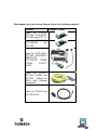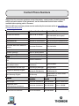
1
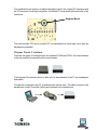
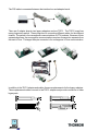
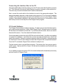
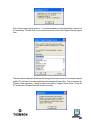
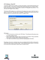
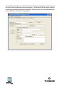
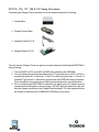
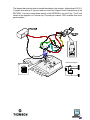
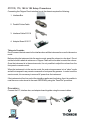
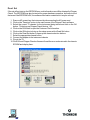
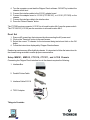
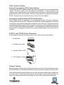
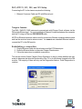
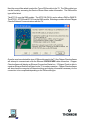
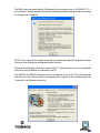
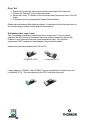
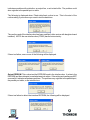
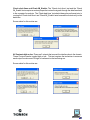
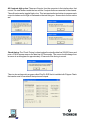
Chipper Check II
User Manual
Contents
What is Chipper Check II (CCII)?...................................................... 4
Chipper Check (CC) vs. Chipper Check II (CCII) ............................. 4
Chipper Check II Interface ................................................................ 5
Connecting the Interface Box to the PC ............................................ 7
CCII Install Software .......................................................................... 7
CCII Software Start-UP .................................................................... 10
Entering the Service Mode .............................................................. 13
CTC175, 176, 177, 186 & 187 Setup Procedure ........................... 14
CTC178, 179, 188 & 189 Setup Procedures ................................. 16
Procedure: .................................................................................. 16
Dead Set ..................................................................................... 18
CTC195, 197 & 203 Setup Procedures.......................................... 19
Procedure: .................................................................................. 19
Dead Set ..................................................................................... 20
Setup MM101, MM102, CTC210, CTC211, and LCOS Chassis .... 20
Procedure: .................................................................................. 21
PTV Convergence Setup ............................................................ 21
Dead Set ..................................................................................... 21
Setup DTV306, DTV307 Chassis ................................................... 22
Service Mode (Manually) ............................................................. 22
TECI1 Switch Position ................................................................ 23
ATC221 and ITC222 Setup Procedure........................................... 23
Procedure: .................................................................................. 24
Dead Set ..................................................................................... 24
DLP, ATC311, 321, 322, and 323 Setup ......................................... 25
Establishing a connection: .......................................................... 25
Dead Set ..................................................................................... 28
Interface Box Diagnostic Tests ........................................................ 29
Frequently Asked Questions ........................................................... 34
Contact Phone Numbers ................................................................. 36
What is Chipper Check II (CCII)?
Chipper Check II is an advanced interface box that provides communication between the TV
set being serviced and a personal computer. The interface converts the I2C bus communication
of the TV to serial communication used by the PC. With the Chipper Check software, the PC
is able to control certain functions of the TV and perform some alignments.
Other functions of CCII are software upgrade, read error codes, and download / restore the
EEPROM (chassis alignment data).
Chipper Check II hardware consists of several items. The hardware items are:
• Chipper Check II interface box
•
Interface Cables (serial and parallel cables)
•
TECI1 Adapter Board and Cables
•
(2) Legacy Adapter Boards
•
ITC222 Cable
You can find additional information about Chipper Check II at: http://www.thomsonnetwork.com.
Chipper Check (CC) vs. Chipper Check II (CCII)
The original interface box worked as designed for chassis of it’s time but as technology
progressed, there was a need to change the interface and along came CCII. The difference
between CC and CCII is the tri-level logic of CCII over the bi-level logic of CC. By going to Trilevel, CCII and a modified CC would be able to interface with the more advanced chassis.
4
The modification was simple, just add the daughter board to the original CC interfaces and
the CC become tri-level logic compatible. A modified CC circuit board will look similar to the
one below:
Daughter Board
The new interface CCII and a modified CC incorporates the tri-level logic circuit and are
backwards compatible.
Chipper Check II Interface
There are two types of interface boxes, the modified CF002 and CF003. A tri-level interface
is the only one that is compatible with current chassis.
The Purpose of the interface box is to allow a PC to be connected to the TV set via adapters
and cables.
To make the connection to the PC, a parallel printer cable is used. This cable connects to the
parallel port on the PC and the Centrex end connects to the interface box.
5
The PS2 cable is connected between the interface box and adapter board.
There are 3 adapter boards; two legacy adapters and one TECI1. The TECI1 board has
many plugs and a switch. These plugs are for connecting different cables for the different
chassis. The switch is for convergence communications on PTV products. Because of their
separate bus lines, the convergence communications requires a connection separate from
the main I2C bus. The larger three pin connector is for convergence I2C bus communication.
In addition to the TECI1 adapter and cables, there are replacements for the legacy adapters.
These replacement cables connect to the TECI1 adapter and provide connection to older
legacy sets.
1
2
3
4
5
6
7
1
2
3
4
5
6
7
6
1
2
3
C
D
E
A
B
F
1
2
3
4
5
6
7
1
2
3
4
5
6
7
1
2
3
4
5
6
7
1
2
3
4
5
6
Connecting the Interface Box to the PC
Using the parallel cable, locate the printer port on the PC and connect the 25-pin Din connector
to it. The other end of the printer cable (Centrex connector) connects to the interface box.
This is the only connection between the PC and the interface box.
Next, connect the serial cable to the interface box and to the appropriate adapter. The
appropriate adapter depends on what chassis is being serviced. Do not connect the adapter
or cable to the instrument being serviced until instructed to do so by the Chipper Check
software. Each chassis is different on the setup and connection point. Information on setup
and hookup is found in the Help files of the Chipper Check program.
CCII Install Software
The Chipper Check software is always changing. To make sure you have the latest version,
go to www.thomsonnetwork.net. Under “Order Chipper Check”, the latest version of software
will be shown and available for download. If you already have the latest, there is no need to
download this version. If not, then download the latest version.
Once downloaded, double click on the EXE file and it will self install. Very little user interface
is required for installation. Just follow the on-screen prompts and when done, the PC will
need to be restarted. Restart is necessary because registry information is changed during
the install and in order for those changes to take effect it requires the computer be restarted.
Once the PC is restarted, Chipper Check software is ready for use.
The first screen to come up is the Welcome screen. This screen is the “are sure you want to
install” screen. Options are OK or Cancel. OK will start the installation and Cancel will stop
the installation.
If your updating a previous version of CCII, the install software will automatically remove any
previous version of Chipper Check.
7
The next user input required screen asks for the “Destination Directory”. This is the directory
in which you want the install program to store the Chipper Check files. It is recommended you
accept the default location but is not necessary.
After the destination is selected the installation process is started and the progress is displayed
for reference only by the following graphic.
When all the files are copied to the destination folder, a screen is displayed indicating the
default port is LPT1. This is the communications port Chipper Check interface uses to
communicate with the PC. If you are already using LPT1 for a printer or other peripheral
device, you must change the INI file to indicate which port to use. The only options are LPT1,
LPT2, or LPT3. Select OK to accept the default LPT1 port.
8
Next is the program group selection. It is recommended you select the default location but
not necessary. This will allow you to customize where you launch Chipper Check program
from.
The last window displayed will indicate that changes have been made to the computer registry
and the PC will need to be rebooted before the changes will take effect. This is important for
Chipper Check operation. Failing to reboot can result in Chipper Check failure. Once the
PC is rebooted, Chipper Check will function correctly.
9
CCII Software Start-UP
To start the Chipper Check software, locate the start button on the task bar with the mouse
pointer and click it. Then point to “Programs and locate the program group “Chipper Check”.
Once in the program group of Chipper Check, locate the CCII program icon and click it. This
will launch the Chipper Check software.
The first time CCII software is run, the Servicer Information entry screen is the first screen to
appear. Once filled in, this screen will not reappear. The Servicer Information entry screen
allows the Servicer to personalize their version of Chipper Check.
Options are:
• Fill in all information and click on the “OK” button. This will prevent this entry screen
from being displayed again.
• Select “Cancel” button to bypass with out entering any information. Doing so will allow
future starts of Chipper Check to display this entry screen.
• The “Help” button launches a pop-up window displaying help information.
Depending on the version of software, the main screen displayed after the Servicer Information
screen is the start screen of Chipper Check. In the following example (Version 1.86), there
are several options depending on what chassis is being serviced.
10
More information about the software can be found in the Help files within Chipper Check
Software.
One screen found in all Chipper Check versions is the “Customer Information Screen”. This
screen allows the technician to enter unique information to generate a file of the stored values
in the main EEPROM of the instrument being serviced. This file can later be used to restore
a corrupt EEPROM for this customer. Since this information is unique to each instrument,
Model and Serial numbers are required to proceed past this screen.
There are three options for this tab. One of the three has to be completed before the program
will allow other tabs to be selected. The options are:
1. Open file
2. Save file
3. Enter Model and Serial numbers
If only generic model and serial numbers are used, the technician will not want to save this
information. Saving with generic information can cause the wrong file to be loaded thus
causing additional problems for the technician / customer.
The store and open file are optional. By storing the information the technician is creating a
file for future use. The open file allows the technician to utilize the saved file feature of Chipper
Check at a latter date. In other words, if the technician saved the file the first time in for repair
and later the set needed the EEPROM replace, the alignment process would be almost
11
eliminated by restoring the customer file for that set. The only requirement would be locating
the correct file and restoring it to the customers set. The Model and Serial number fields are
the best way to distinguish between instruments. Because of this, the model and serial fields
need to be filled in to advance in the program.
12
Entering the Service Mode
During normal operation, newer chassis (CTC195, 197, 203, 210, 211, MM101, 102, DTV306,
307, and LCOS) are continuously monitoring the I2C bus for an acknowledgment from the
EEPROM that resides in the Chipper Check interface box. When these newer chassis detect
that the Chipper Check EEPROM has been connected to the I2C bus, the chassis automatically
go into the Service Mode. The chassis must supply the I2C clock during this auto-detection,
which unfortunately, runs approximately 5 times faster than the Chipper Check interface box.
The interface box supplies the I2C clock once the chassis is in the Service Mode. The speed
of the I2C clock from the chassis, combined with the extra resistance and capacitance of the
interface cables and the interface box, will occasionally prevent the EEPROM auto-detection
from working. When the auto-detection does not work, use the manual procedure described
below. When the auto-detection does not work, the chassis will usually shut down and may
have to be unplugged before it will power up again.
Manually putting the instrument into the service mode:
This routine applies to all chassis except DTV306 and DTV307.
1. With the instrument ON, press and hold the Menu button.
2. Press and release the Power button then press and release the Volume UP button.
3. Release the Menu button and the instrument should display the ROM version, a ‘P’
number (parameter), and a ‘V’ number (value).
4. Using either the remote hand unit or the front panel buttons, press and hold the Volume
DOWN button until the ‘V’ value displays 200.
5. Now press the Channel UP button to enter the service mode.
After the instrument is in the service mode the interface box maybe connected. If connected
to the interface box and the instrument is NOT in the service mode, the instrument may shut
down. If this happens, AC power must be removed to restart the set. Once the chassis is in
the service mode and the interface is connected to the chassis, Chipper Check software will
be able to communicate with the set.
13
CTC175, 176, 177, 186 & 187 Setup Procedure
Connecting the Chipper Check interface box to the chassis requires the following:
1. Interface Box
2. Parallel Printer Cable
3. Interface Cable 212118
4. Adapter Board 212121
The only function Chipper Check can perform on these chassis is initializing the EEPROM to
factory settings.
1. The set MUST be OFF and UNPLUGGED when initializing the EEPROM.
2. You must determine if the set has a Motorola or ST microprocessor (U3101) U3101 is
marked with either ST or Motorola. If the IC is a Motorola ground pin 1, if the IC is
marked ST ground pin 2. Retain this ground while the EEPROM is being initialized.
Once reinitialized, remove the ground before returning the set to normal operation.
3. Prior to initializing the EEPROM, an external 5 volt supply and a 1K resistor must be
connected per the diagram on the next page. DO NOT apply the external 5 volts until
after the chassis is selected in the Chipper Check software. If 5 volts is applied before
the chassis is selected a NO COMMUNICATIONS error may result.
14
The diagram below shows how to connect the adapter to the chassis. Adapter board 212121,
7 jumper wires and an IC clip are used to connect the Chipper Check interface box to the
EEPROM. You may connect leads directly to the EEPROM or use an IC clip. The IC clip
shown in the diagram is a Pomona clip, Pomona part number 5108, available from most
parts suppliers.
E
D
F
Schematic Diagram
IC
D
E
5V
EEPROM
F
15
CTC178, 179, 188 & 189 Setup Procedures
Connecting the Chipper Check interface box to the chassis requires the following:
1. Interface Box
2. Parallel Printer Cable
3. Interface Cable 212118
4. Adapter Board 212117
Things to Consider:
Do not connect the instrument to the interface box until the instrument is on and in the service
mode.
Before putting the instrument into the service mode, preset the volume to a low level. Do not
set the volume to absolute minimum or Chipper Check will not be able to control the volume.
Once the instrument is in the service mode, it is not possible to adjust the volume from the
front panel or remote control.
When the instrument is in the service mode, the main microprocessor is in a “slave” mode
and will not respond to any remote commands or front panel key presses. In order to exit the
service mode, it is necessary to remove AC power from the instrument.
If the instrument will not turn on but the standby supplies are functioning, then it is possible to
read the error codes stored in the main EEPROM by using the “Dead Set” procedure.
Procedure:
Connect the PC, Interface box, and adapter board together using the correct cables.
16
1. Place the instrument in the service mode.
a. With the instrument ON, press and hold the Menu button, press and release the
power button then press and release the volume + button. Release the Menu
button. The instrument should now display the ROM version and P: 00 V: 00.
b. Using the remote hand unit or the front panel button, press and hold the volume
(-) until the “V” value is 200.
c. Now press the Channel “up” button to enter the service mode.
2. Connect the adapter board to the interface plug J3104 (location 20BB) on the chassis.
3. Start Chipper Check Program and select the Detect Chassis button.
If communication is not established, the following screen will be displayed.
17
Dead Set
If the set will not start up, the EEPROM error code information can still be obtained by Chipper
Check. The EEPROM may also be tested for proper hardware operation, but keep in mind
that even if the EEPROM is OK, the software information contained in it may be corrupt.
1. Remove AC power from the instrument by disconnecting the AC power cord.
2. Click on the “Dead set” button in the main screen of the Chipper Check software.
3. Select the correct TV chassis for the instrument being tested and click on the OK
button. This brings up Chipper Check Version 1.93.
4. Click on the OK button to open the Customer File Information.
5. Click on the OK button to bring up the setup screen with a Dead Set button.
6. Click on the Dead Set button to open up the chassis selection buttons.
7. Select the appropriate chassis button
8. Connect the adapter to the instrument chassis
9. Plug in the TV.
10. Click OK and Chipper Check software will read the error codes stored in the chassis
EPROM and display them.
18
CTC195, 197 & 203 Setup Procedures
Connecting the Chipper Check interface box to the chassis requires the following:
1. Interface Box
2. Parallel Printer Cable
3. Interface Cable 212118
4. Adapter Board 212121
Things to Consider:
Before putting the instrument into the service mode, preset the volume to a low level. Once
the instrument is in the service mode, it is not possible to adjust the volume from the front
panel or remote control.
Do not connect the instrument to the interface box until the instrument is on, in the Service
Mode, and the Chipper Check program is running with the first screen of the program visible
(the parallel port is initialized just prior to the first screen being displayed). Failure to comply
with this requirement may cause the instrument to shut down.
Once the instrument is placed into the service mode, the main microprocessor is placed into
the “slave” mode. It will not respond to any remote commands or front panel key presses. In
order to exit the service mode, it is necessary to remove AC power from the instrument.
If the instrument will not turn on, it is still possible to read error codes in the main EEPROM as
long as the standby supplies are functioning. Go to the “Dead Set” section for the procedure.
f the instrument will not turn on but the standby supplies are functioning, then it is possible to
read the error codes stored in the main EEPROM by using the “Dead Set” procedure.
Procedure:
1. Put the CTC195, 197 or 203 into the Service Mode.
2. With the computer OFF, connect your computer to the interface box using the standard
parallel printer cable.
3. Apply power to the Chipper Check interface box CCF002.
19
4. Turn the computer on and start the Chipper Check software. DO NOT try to detect the
chassis at this time!
5. Connect the interface cable to the 212121 adapter board.
6. Connect the adapter board to J13120 (CTC195/197), or J13101 (CTC203) on the
chassis.
7. Connect the interface cable to the interface box.
8. Press the “Detect Chassis” button.
The CTC203 service connector (J13101) is at board location AA-6 near the power switch.
The CTC195/197 (J13120) service connector is at board location KK-6.
Dead Set
1. Remove AC power from the instrument by disconnecting the AC power cord.
2. Click on the “Dead set” button in the main screen.
3. Select the correct TV chassis for the instrument being tested and click on the OK
button.
4. Follow the instructions displayed by Chipper Check software.
Dead set procedures may differ slightly by chassis. It is important to follow the instructions for
the chassis being serviced to ensure proper communication.
Setup MM101, MM102, CTC210, CTC211, and LCOS Chassis
Connecting the Chipper Check interface box to the chassis requires the following:
1. Interface Box
2. Parallel Printer Cable
3. Interface Cable 212118
4. TECI1 Adapter
Things to Consider:
20
When the instrument is connected to Chipper Check, the main microprocessor, is placed into
the “slave” mode. It will not respond to any remote commands or front panel key presses. In
order to exit this service mode, it is necessary to remove AC power from the instrument.
f the instrument will not turn on but the standby supplies are functioning, then it is possible to
read the error codes stored in the main EEPROM by using the “Dead Set” procedure.
Procedure:
Chassis Communications (TECI1) Switch Position
The switch on the TECI1 adapter needs to be in the correct position to communicate with the
chassis. The other position is for convergence communication. To put the switch in the
correct position, locate the three (3) pin connector next to the switch. Slide the switch to the
position closest to the 3-pin connector. This is the correct position for chassis communication.
NOTE: The switch can be located on the top or the bottom of the adapter.
1. Connect your computer to the interface box and the interface box to the TECI1 adapter.
2. Apply power to the Chipper Check interface box.
3. Turn the computer on and start the Chipper Check software. DO NOT select chassis
at this time!
4. Connect the adapter board to the service connector J13202 of the I/O board.
5. Select the appropriate chassis type (Do NOT try to Detect Chassis).
PTV Convergence Setup
When Chipper Check is connected to the convergence module, using the 3-conductor
convergence cable, the switch lever is moved away from the 3-pin Convergence plug which
lifts the ground connection to the I/O board. The ground switch is necessary because the
ground of the convergence module can not be connected to the ground of the I/O board
without shifting convergence. If convergence is set with the switch in the wrong position,
convergence will shift as soon as the interface adapter is removed from the I/O board.
Dead Set
1. Remove AC power from the instrument by disconnecting the AC power cord.
2. Click on the “Dead set” button in the main screen.
3. Select the correct TV chassis for the instrument being tested and click on the OK
button.
4. Follow the instructions displayed by Chipper Check software.
Dead set procedures may differ slightly by chassis. It is important to follow the instructions for
the chassis being serviced to ensure proper communication.
21
Setup DTV306, DTV307 Chassis
Connecting the Chipper Check interface box to the chassis requires the following:
1. Interface Box
2. Parallel Printer Cable
3. Interface Cable 212118
4. TECI1 Adapter
Things to Consider
The DTV30x uses the TECI1 adapter. Make sure the switch is set to the position closest to
the white 3-pin convergence connector for chassis communication.
It is best to allow Chipper Check to be detected by the chassis and automatically enter the
Service Mode. This is accomplished by connecting the Chipper Check interface board to
the service connector on the I/O board. When the service mode is entered manually on the
DTV306 or DTV307, the DM module will not respond to FPA key presses or IR remote control
commands. When the service mode is entered automatically by connecting Chipper Check,
the DM module remains active.
Service Mode (Manually)
1. Press the TV·DIRECTV and Chan-DN buttons simultaneously and release them.
2. Select Service Mode to display the “P” and “V”.
3. When the ‘P’ & ‘V’ values appear at the bottom of the screen, press VOL-UP or VOLDN buttons on the FPA or a remote control to change the V value to V=200.
4. Press the Chan-UP button to enter the service mode.
NOTE: The Tilt control moves all the way counter-clockwise as soon as the service mode is
entered and is considered normal. Chipper Check will set Tilt at 50% as soon as DTV306 is
selected.
22
TECI1 Switch Position
Chassis Communications (TECI1) Switch Position
The switch on the TECI1 adapter needs to be in the correct position to communicate with the
chassis. The other position is for convergence communication. To put the switch in the
correct position, locate the three (3) pin connector next to the switch. Slide the switch to the
position closest to the 3-pin connector. This is the correct position for chassis communication.
NOTE: The switch can be located on the top or the bottom of the adapter.
Convergence Communications (TECI1) Switch Position
When Chipper Check is connected to the convergence module, using the 3-conductor
convergence cable and the TECI1 adapter, the switch lever is positioned away from the 3-pin
Convergence plug which lifts the ground connection to the I/O board. The ground switch is
necessary because the ground of the convergence module can not be connected to the ground
of the I/O board without shifting convergence. If convergence is set with the switch in the
wrong position, convergence will shift as soon as the interface adapter is removed from the I/
O board.
ATC221 and ITC222 Setup Procedure
Connecting the Chipper Check interface box to the chassis requires the following:
1. Interface Box
2. Parallel Printer Cable
3. Interface Cable 212118
4. TECI1 Adapter / Cables
Things to Consider:
Before plugging in Chipper Check, preset the volume to a low level. Once the instrument is in
the service mode, it is not possible to adjust the volume from the front panel or remote control.
Once the instrument is placed into the service mode, the main microprocessor is placed into
the “slave” mode. It will not respond to any remote commands or front panel key presses. In
order to exit the service mode, it is necessary to remove AC power from the instrument.
23
f the instrument will not turn on but the standby supplies are functioning, then it is possible to
read the error codes stored in the main EEPROM by using the “Dead Set” procedure.
Procedure:
Chassis Communications (TECI1) Switch Position
The switch on the TECI1 adapter needs to be in the correct position to communicate with the
chassis. The other position is for convergence communication. To put the switch in the
correct position, locate the three (3) pin connector next to the switch. Slide the switch to the
position closest to the 3-pin connector. This is the correct position for chassis communication.
NOTE: The switch can be located on the top or the bottom of the adapter.
1. Apply power to the Chipper Check box. Connect the interface box to the PC and start
Chipper Check software.
2. Select the TECI1 adapter and connect it to the Chipper Check interface box.
3. Select the correct adapter cable for the television you will be communicating with and
plug it into the TECI1 adapter:
ATC221 use the 7 to 4 pin connector cable.
ITC222 uses the 7 to 10 pin connector cable.
4. Plug the adapter cable into the television. The connector is located on the AV panel
and is accessible without removing the back cover on the ITC222 and ATC221.
5. Communication is established when the customer information screen appears on the
PC screen (Chipper Check software).
EEPROM and Diagnostics are the only tabs that Chipper Check can perform on these chassis.
Alignments are done manually using a remote or the FPA buttons. See the appropriate
service data for the alignment procedures.
Dead Set
By selecting the ‘Dead Set” button on the start screen of Chipper Check, brings up the chassis
selection screen. Select the chassis being serviced and follow the instructions on the Chipper
Check software screen.
24
DLP, ATC311, 321, 322, and 323 Setup
Connecting the PC to the chassis requires the following:
1. Ethernet Crossover Cable and PC with Ethernet port
Things to Consider:
The DM2 / DM2CR / DM3 instruments communicate with Chipper Check software via the
DM module Ethernet port. You must establish an Ethernet Connection between the computer
and the TV using an Ethernet CROSSOVER cable.
NOTE: An Ethernet crossover cable is used to connect two Ethernet computers without a hub
and has the send and receive wires crossed. You cannot use a standard Ethernet cable to
connect the PC to the DM module.
Establishing a connection:
1. Plug the Ethernet Cable into the television and the PC Ethernet port.
2. Press the Ethernet button on the main Chipper Check screen.
3. Follow the instructions to establish a connection.
The second screen (Select Chipper Check Operation) is used to select whether the user
wants to diagnose and align the functionality of the TV or do a Software Upgrade to the DM
module. The majority of users will only use the Diagnostics feature. Press Diagnostics to
continue.
25
Next the user will be asked to select the Type of DM module in the TV. The DM module type
can be found by accessing the Service Screen Menu under Information. The DM module
type will be listed.
The ATC311 uses the DM2 module. The ATC311M (DLPs) can be either a DM2 or DM2CR.
The ATC321, ATC322 and ATC323 use the DM3 module. Selecting a module will start Chipper
Check’s Ethernet Communications with the TV.
Once the user has selected the type of DM module used in the TV, the Chipper Check software
will attempt to communicate over the Ethernet CROSSOVER cable connection. Chipper
Check software will display an Ethernet Connection Status box. If Chipper Check is able to
create an Ethernet Socket it will listen for the TV to make connection. Chipper Check software
will also check the computer’s Ethernet settings and display information necessary for the
connection to be completed depending on the DM module type.
26
The DM2 module requires that the IP address of the computer be set to 169.254.36.171. If
the computer’s settings are different then the following box will be displayed with instructions
for changing the IP address.
NOTE: If your computer is normally connected to a network write down the original IP address
so that you can change the settings back when finished.
Pressing OK will display a Warning to reboot the PC. Communication can not be estiblished
until the correct IP address is reconized by the PC.
The DM2CR and DM3 IP addresses can be changed to those of the PC by following the
instructions on the following screen that appears after Chipper Check software begins the
“Listening” for an Ethernet connection.
27
Dead Set
1. Remove AC power from the instrument by disconnecting the AC power cord.
2. Click on the “Dead set” button in the main screen.
3. Select the correct TV chassis for the instrument being tested and click on the OK
button.
4. Follow the instructions displayed by Chipper Check software.
Dead set procedures may differ slightly by chassis. It is important to follow the instructions for
the chassis being serviced to ensure proper communication.
Old Adapters (No Longer in Use)
Two of the adapters have been replaced and are no longer used. If you have these
adapters, they will function for the chassis they were originally designed to be use with.
However, it is recommended that only current adapters be used. If you have the
replacement (TECI1 adapter) to these adapters, they may be discarded.
Numbers found on these adapters are 370 and 371.
CCAB3685 (370)
CCAB3684 (371)
Legacy adapters, CCAB2121 and CCAB2117 are only available for a limited time in the
complete kit CC1K. They are replaced by the TECI1 and cable kit as well.
28
Interface Box Diagnostic Tests
Chipper Check II software incorporates several diagnostic tests to verify communication
between the interface, adapter, and PC. To do all the tests requires the interface be connected
to the PC and one adapter or cable / adapter combination be connected to the interface.
Most of the circuitry inside the interface box can be tested without any adapters being
connected. Running the ‘Check data lines’ and the ‘Detect EEPROM’ routines checks 75%
of the interface circuitry. The remaining circuitry is tested by using external jumpers and the
#212121 adapter board (used with CTC195/197/203) or the TECI1 and Cable adapter. The
components required to do all diagnostic tests are:
·
Interface box and cables
·
·
Adapter 212121
Jumper Cable
·
·
TECI1 Adapter
Cable
+
OR
+
1
2
3
4
5
6
7
C
D
E
A
B
F
To start the diagnostic tests, click on the Diagnostic tool bar and select the test you want to
perform.
Check data lines: There are two I2C data lines, going from the interface box to the computer.
During the data line test, the data lines are toggled high and low by configuring tri-state buffers
and internally setting the data lines high or low inside the interface box. If this test fails, it
29
indicates a problem with a data line, an output line, or a tri-state buffer. The problem could
also originate in the parallel port or cable.
The following is displayed when ‘Check data lines’ routine is run. This is the start of the
routine asking if you are sure you want to test the data lines.
The next box asks if the interface box has been modified (older version with daughter board
installed). NOTE: the new interface box (CF003) has the extra circuitry.
If there is a failure, one or more of the following will be displayed.
Detect EEPROM: This routine test the EEPROM found in the interface box. It writes to the
EEPROM and then attempts to read what was just written. If the writing and reading are NOT
successful it indicates a hardware problem. The problem may originate in the parallel port,
the parallel port cable, or the interface box.
If there is a failure to detect the interface EEPROM, the following will be displayed.
30
Check clock lines and Check IM_Enable: The ‘Check clock lines’ test and the ‘Check
IM_Enable’ tests require an extern jumper that routes the signals through the data lines back
to the computer for analysis. The ‘Check data lines’ test should always be performed prior to
running the ‘Check clock lines’ and ‘Check IM_Enable’ tests because those tests rely on the
data lines.
Screen shots for this routine are:
All 5 outputs high or low: There are 5 outputs that connect the interface box to the chassis.
These 5 outputs can be toggled high or low. This test requires the technician to measure
each output to make sure it is high or low based on the test being run.
Screen shots for this routine are:
31
All 8 outputs high or low: There are 8 inputs, from the computer to the interface box, that
control 3 tri-state buffers inside the box and the 5 outputs that are connected to the chassis.
These 8 inputs can be toggled high or low. This test requires the technician to measure each
output to make sure it is high or low based on the test being run. Screen shots for this routine
are:
Check timing: The ‘Check Timing’ routine toggles the standby data line 200,000 times and
puts a 10 KHz square wave on the data line for 10 seconds. The cursor should change from
an arrow to an hourglass for approximately 10 seconds if the timing is correct.
There is also a diagnostic program called ChipFix.EXE that is installed with Chipper Check
that can be used to exercise all the inputs and outputs.
32
Options
The options tool bar is used to set Chipper Check software options such as:
· Initialize Port
· Parallel Port
· Serial
· Initialize CC EEPROM
· Usage Log
· Clock Speed
To use the diagnostic routines, the correct port settings need to be used. Under the options
tool bar the important one is Parallel Port. Make sure the correct port is selected in the
options tool bar for the one connected to the Chipper Check interface. Failure to connect to
the correct port will result in an interface failure under the diagnostic routines. Both the connected
port and the software need to match. Example; if using LPT1 main printer port on the PC, the
software under options, Parallel Port, needs to be LPT1. If LPT2 was selected the PC would
not communicate with the interface and the diagnostic routines would fail.
Frequently Asked Questions
I’m using the Ethernet connection to connect to the set but Chipper Check will not
communicate with the set. What do I do?
The Ethernet connection requires a CROSSOVER cable, a standard Ethernet cable will
not work. You need to purchase a CROSSOVER cable.
Can Chipper Check work with a USB connection?
Currently, Chipper Check hardware and software does not work with USB.
I just received Chipper Check and there are no instructions. What do I do?
Load the software on your laptop. Once the software is up and running, it will prompt you to
select a chassis. After selecting a chassis, the software will provide instructions on how to
hook Chipper Check up to the chassis.
Where is the Chipper Check CCF002 upgrade kit?
CCF002 is no longer available. You will need to buy Chipper Check II available on-line at
Thomson Network.
Chipper Check is not communicating with this TV has worked with other sets.
What do I do?
Verify you have the latest software version of Chipper Check. If you are not sure what is the
latest, go to the web site Thomson network and download the latest version.
I have the latest software but Chipper Check is not communicating with the TV.
What do I do?
Please make sure you check all your connections. If there seems to be a problem with
Chipper Check, you can run its internal diagnostics program. Just open up the Chipper
Check program, select the Diagnostics dropdown and run all diagnostics functions. If there
is a problem, you can troubleshoot Chipper Check yourself with schematics and parts list
located on Thomson Network. If you need to contact us, you can send us an email.
34
What adapter do I need to hook Chipper Check to the following chassis?
Chassis
Diagram / Photo
Used
for
CTC17x,
CTC18x, CTC195/197,
CTC203, and ATC113
Used for CTC178/179,
CTC188/198,
and
CTC185
Used for CTC210/211,
CTC203, DTV306/307,
MM101/102,
CTC195/197, ITC008,
ITC222,
ATC311,
LCOS
Used
for
ATC311,
ATC321, ATC322, and
ATC323. Includes all
DLPs with Ethernet
connection.
Used for ATC332 and
ATC336 DLPs
35
Contact Phone Numbers
Always have the consumer purchase receipt information, model number (including service
suffix) and serial number of the instrument, and the Authorized Service Center number
available before placing calls to Thomson.
Most Use & Care or accessory issues can be resolved by the consumer online at www.RCA.com
or www.rcascenium.com .
Con su m er Issu e:
In f orm a t i on L oca t i on
Con t a ct Det a i l s
U se a n d ca re Issu es:
Refer to IB or web site
800-336-1900 ( A u toma ted )
580-634-0123 ( Live A gen t)
Comp lex In sta lla tion s
Get Con n ected Services
888-206-3359
Rep la cemen t IB
Web site or service d a ta
http://tv.rca.com/en-U S/RLSearch.html
T V Gu id e+ Issu es
Gemsta r A ssista n ce
580-634-0195
Con su mer issu e with service or
p rod u ct
Con su mer Rela tion s
580-634-0151
Service Con tra ct
Service Con tra cts
800-283-6193
Cosmetic d a ma ge
Refer to Sellin g Dea ler
Sh ip p in g Da ma ge
Refer to Delivery A gen t
P a rts
Ord ered P a rt, received in correct
p a rt
Ord ered P a rt, received in correct
p a rt mu ltip le times
P a rt b a ck ord er over 30 d a ys
In stru men t Wa rra n ty E ligib le
P a r t W a rra n t y E l i g i b l e
S erv i ce
Hi n t s & T i p s:
Comp on en t level
trou b lesh ootin g a ssista n ce
Ch ip p er Ch eck
Con firm Service Con tra ct
36
Con ta ct Distrib u tor
T h omson Tech n ica l
A ssista n ce
Field Service M a n a ger
Refer to IB , Con su mer
Receip t & E SI M on th ly
580-634-0160
580-634-0170
P a rtsFin d er II on most recen t
E SI M on th ly CD
P a rtsFin d er II on most recen t
E SI M on th ly CD
In f orm a t i on
Con t a ct
L oca t i on
Det a i l s
Tech n ica l A ssista n ce 580- 634- 0160 Select "T E CH T IP S"
E SI M on th ly
Tech n ica l A ssista n ce 580- 634- 0160
Select “OT HE R”
Tech n ica l A ssista n ce 580- 634- 0160
Select "OT HE R"
Service Con tra cts
800- 283- 6193
TTCCIIUM