1
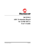
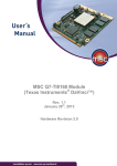
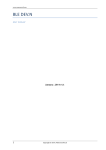
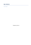
1300 Henley Court Pullman, WA 99163 509.334.6306 www.digilentinc.com Universal Development Board™ Reference Manual Revised January 15, 2014 This manual applies to the UDB rev. E Table of Contents Table of Contents .................................................................................................................. 1 Overview............................................................................................................................... 3 1 Power Supply ................................................................................................................. 5 1.1 USB Power ........................................................................................................................ 5 1.2 External Power Supply ..................................................................................................... 5 1.3 Power Supply Circuit Description ..................................................................................... 5 1.4 9V0 Power Supply for PIM/PICtail™ Plus Bus .................................................................. 5 2 USB to UART Serial Converter......................................................................................... 6 3 PIM Module ................................................................................................................... 6 3.1 4 PICtail™ Plus Card Edge Expansion Connectors ............................................................... 7 4.1 5 On-Board PIC32MX360.................................................................................................... 7 PIM Bus............................................................................................................................. 8 DIP Sockets .................................................................................................................... 8 5.1 DIP Bus Program Signal Jumpers ...................................................................................... 9 5.2 DIP Bus Clock Jumper ....................................................................................................... 9 5.3 DIP Bus Header ............................................................................................................... 10 5.1.1 8-Pin DIP Package.................................................................................................... 10 5.1.2 14-Pin DIP Package.................................................................................................. 10 5.1.3 16-Pin DIP Package.................................................................................................. 10 DOC#: 6021-502-000 Copyright Digilent, Inc. All rights reserved. Other product and company names mentioned may be trademarks of their respective owners. Page 1 of 27 Universal Development Board™ Reference Manual 5.1.4 6 20-Pin DIP Package.................................................................................................. 11 In Circuit Serial Programing (ICSP) ................................................................................ 11 6.1 ICSP Connector ............................................................................................................... 11 6.2 Tag connector ........................................................................................................... 11 6.3 Programming Signals ................................................................................................. 11 7 6.3.1 IC2 Program Jumper Settings .................................................................................. 12 6.3.2 IC3 Program Jumper Settings .................................................................................. 12 6.3.3 IC3_GS Program Jumper Settings ........................................................................... 13 6.3.4 IC4 Program Jumper Settings .................................................................................. 13 Oscillator Options ........................................................................................................ 13 7.1 High Frequency Oscillator .............................................................................................. 13 7.2 Low Frequency Oscillator ............................................................................................... 14 8 I2C Interface ................................................................................................................. 14 9 Pmod Interface ............................................................................................................ 15 9.1 Pmod Connector JA ........................................................................................................ 16 9.2 Pmod Connector JB ........................................................................................................ 16 10 Serial EEPROM ............................................................................................................. 16 11 User I/O Devices .......................................................................................................... 17 11.1 Analog Input (Potentiometer) .................................................................................... 17 11.2 Switches ...................................................................................................................... 17 11.3 LEDs............................................................................................................................. 17 Appendix A: PICtail™ Plus/PIM Bus Connections .................................................................. 18 Appendix B: PICtail™ Plus/PIM Bus Connections .................................................................. 22 Appendix C: User I/O Devices .............................................................................................. 27 Copyright Digilent, Inc. All rights reserved. Other product and company names mentioned may be trademarks of their respective owners. Page 2 of 27 Universal Development Board™ Reference Manual Overview The Universal Development Board (UDB) is a microcontroller development board intended to use with a wide variety of PIC microcontrollers from Microchip®. It was designed to support most 3.3V, PIC microcontrollers in 8bit, 16-bit, or 32-bit varieties. It will accommodate a wide range of Microchip PIM processor modules as well as DIP packaged parts with pin counts from 8-pin to 28-pin. Three DIP sockets are provided: 20/14/8 PIN 8-bit PIC, 28 PIN 8-bit PIC, and 28-pin PIC24/dsPIC33/PIC32MX. This board also has discrete I/O elements and 2 Pmod connectors for further device evaluation or product development capability. Expansion connectors are provided that are compatible with the Microchip PICtail™ Plus line of expansion modules. In addition to the PIM connector and DIP sockets, a PIC32MX360 microcontroller is also provided for use without the need for additional PIM or DIP socketed processors. The Universal Development Board is designed to be compatible with the Microchip Explorer 16 development board. The layout of the PIM connector and PICtail™ Plus bus connections are physically and electrically compatible with the Explorer 16, and many Microchip demonstration programs for the Explorer 16 will work with the UDB. Microchip® PIC32MX360 microcontroller PICTail™ Bus/PIM connector ICSP Header 20/14/8 Pin 8-Bit PIC 28 Pin 8-Bit PIC 28 Pin PIC24/dsPIC33/PIC32MX Two Pmod Connectors Three Push Buttons Two Analog POTs Eight user LEDs USB Serial Convertor Power from header or USB Convertor 3.3V operating voltage 8 MHz Oscillator Serial EEPROM Universal Development Board Copyright Digilent, Inc. All rights reserved. Other product and company names mentioned may be trademarks of their respective owners. Page 3 of 27 Universal Development Board™ Reference Manual 26 25 27 23 24 28 29 22 1 2 3 21 4 5 6 7 8 9 20 19 10 17 15 11 12 18 16 14 13 Call Out Function Call Out Function 1 J21 Power Select Jumper 16 Potentiometer 2 Power Switch 17 PIC 32 Microcontroller MX360 3 Reset Button 18 PIM Header 4 In Circuit Serial Program Connector 19 User I/O Buttons 5 SPI EPROM Enable 20 User I/O LEDs 6 Programming Jumpers 21 GND Reference 7 PIC32 Current 22 PICtail Plus Connector 8 USB Serial Converter 23 PIM header 9 USB UART Reset 24 DIP header 10 PIC 32 Enable 25 Programming Jumpers 11 I2C Connector 26 10/14/8 8 Bit PIC 12 GND Reference 27 28 Pin Pic 24/ dsPIC33/ PIC32 13 PIM Socket 28 28 Pin 8 BIT PIC 14 Pmod Connector 29 DIP current measurment 15 PIM current measurement jumper Copyright Digilent, Inc. All rights reserved. Other product and company names mentioned may be trademarks of their respective owners. Page 4 of 27 Universal Development Board™ Reference Manual 1 Power Supply The UDB can be powered in one of two ways, either by a bench supply or a wall wart type power supply attached to the power header, J20; or from the USB connector, J23, associated with the USB serial convertor. The UDB is intended to be operated from a regulated 5V power source, however with certain restrictions, a different supply voltage can be used. The absolute maximum voltage that should be applied to the power header is 6V. If an external power source other than a regulated 5V supply is used, the voltage on the VCC5V0 bus will be the voltage of the external supply, and the test points on the board labeled 5V will actually be at the voltage of the external supply. 1.1 USB Power To power the board with from the USB use a USB 2.0 A to Mini B cable to connect the PC to the UDB via connector J23. The Jumper at J21 (power select) must be placed in the USB position and the power switch, SW1, must be in the ON position. When the board is powered, the LED at LD8 will be illuminated. 1.2 External Power Supply To power the board using an external power supply connected to J20 (EXT Supply 5VDC), the jumper at J21 (Power Select) must be placed on the EXT position. In order for the board to be powered the switch at SW1 must be in the ON position, when the board is powered, the LED at LD8 will illuminate. If SW1 is in the OFF position the UDB is not powered. A fail to power can also occur if the jumper at J21 is in the USB position. Connector J20 is a two pin header using 100mil spaced, 0.25mil square posts. An MTE style connector or clip leads can be used to supply power to this header. The proper polarity is marked on the board. A Shotkey diode, D5, is provided for reverse polarity protection. 1.3 Power Supply Circuit Description All on-board circuits operate at 3.3V. The primary regulated power bus VCC3V3 is powered by a voltage regulator circuit made up of IC9, a Microchip MCP1703 LDO voltage regulator and the associated input and output capacitors C32, C33 and C34. This regulator is rated for a maximum dropout of 625mV. To ensure that the regulator output is the proper 3.3V, the minimum voltage applied to the input of the regulator should be 4V. Allowing for the forward drop across the reverse polarity protection diode, D5, in the input circuit, the minimum external supply voltage should be 4.4V. In addition to the main voltage regulator, a second regulator is used to provide power to the USB serial converter circuit. This regulator is made up of IC11, a Microchip TC1014 LDO voltage regulator and the associated input and output capacitors C28 and C29 and bypass capacitor C30. This regulator is always powered from the USB connector J23, and therefore, power is only supplied to the USB serial converter when J23 is connected to a live USB port. 1.4 9V0 Power Supply for PIM/PICtail™ Plus Bus Some Microchip PICtail™ Plus modules require a 9V power supply to power some of their functions. There is no 9V power supply on the UDB board. If a PICtail™ Plus module is being used that requires the 9V power supply, an external, regulated 9V supply can be attached at J5 to provide this voltage. Jumper J5 is an unloaded, two pin header in the upper right corner of the board. Note the polarity marking on the board as it is not internally protected from reverse polarity. Copyright Digilent, Inc. All rights reserved. Other product and company names mentioned may be trademarks of their respective owners. Page 5 of 27 Universal Development Board™ Reference Manual 2 USB to UART Serial Converter The MCP2200 is a USB-to-UART serial converter which enables USB connectivity in applications that have a UART interface. The serial signals USB-RXD, USB-TXD, USB-CTS, and USB-RTS are available at connector J22, to the right of USB connector J23. The signal names are labeled on the board. Jumper wires can be used to connect the serial interface signals to locations on either the DIP bus or the PIM bus to allow access to the serial interface from a microcontroller in the PIM socket, any of the DIP sockets, or the on-board PIC32MX360. In order to use the MCP2200 USB serial converter, it is necessary for the appropriate drivers to be installed on the host computer. The necessary drivers as well as a configuration utility and other support software can be downloaded from the MCP2200 product page on the Microchip web site. Jumper JP10, labeled UART USB RESET on the board, can be used to hold the MCP2200 in reset. Placing a shorting block on JP10 will cause the MCP2200 to be held in reset. This can be useful when using a USB port to power the board and the serial interface isn’t being used. Normally, when the USB cable is connected to a PC, the MCP2200 will be enumerated on the USB bus and the host computer will expect the MCP2200 driver to be loaded. Use of this jumper allows the board to be USB powered without the need for the MCP2200 driver to be installed. The MCP2200 also has 256-bytes of integrated user EEPROM. There are two LEDs connected to the USB-to-UART serial converter, LD12 which turns on during a transmit process and LD13 which turns on during a receive process. Refer to the Microchip data sheet for the MCP2200 for more detailed information about the operation of the USB serial converter circuit. 3 PIM Module The UDB was designed with the ability to use detachable PIM processor modules. It will work with 16-bit (PIC24 and dsPIC33) PIMs as well as 32-bit (PIC32) PIMs compatible with the Microchip Explorer 16 development board. PIM processor modules are installed onto the pattern of vertical pins at the location labeled PIM Socket on the board. PIMs are visually indexed for proper orientation. The PIM is always installed with the notched corner mark to the upper left. When installing or removing a PIM module, use care to ensure that the pins of the PIM connector socket properly seat into the socket on the PIM and take care to not bend the pins of the PIM socket pattern on the board. Jumper JP9, labeled PIM Current on the board, can be used to measure the power supply current being consumed by the PIM module. To measure PIM current, remove the shorting block from JP9 and attach an ammeter in series between the two pins of JP9. When using a PIM module and not measuring current consumption of the PIM, ensure that the shorting block is installed on JP9. The PIM will not receive power if the shorting block is not installed. The jumper at JP2 is used to enable or disable the on-board PIC32MX360 microcontroller. When using a PIM, ensure that the shorting block is removed from JP2. This will cause the on-board PIC32MX360 to be held in reset. If the shorting block is not removed, the signals from the on-board PIC32MX360 will interfere with signals from the processor in the PIM, causing erratic operation, and possibly damaging one or both processors. The combination of the on-board PIC32MX360 and the ability to use PIM processor allows the UDB to support most 3V, 16-bit and 32-bit PIC and dsPIC® microcontrollers. When using PIM modules with the UDB board, refer to the Microchip information sheet for the PIM being used for any necessary information about how the microcontroller signals are connected to the PIM Socket pin positions. Copyright Digilent, Inc. All rights reserved. Other product and company names mentioned may be trademarks of their respective owners. Page 6 of 27 Universal Development Board™ Reference Manual Many Microchip PIMs are not wired straight through and it is necessary to refer to the Microchip PIM information sheet to understand how they are wired. 3.1 On-Board PIC32MX360 The UDB has a PIC32MX360F512L microcontroller soldered onto the board. This microcontroller is wired to the PICtail™ Plus bus in the same manner as would be the case for a PIM plugged into the PIM Socket. This allows the UDB board to be used for PIC32 application development without requiring the use of PIM or DIP socketed microcontrollers. Jumper JP11, labeled PIC32 Current on the board, can be used to measure the power supply current being consumed by the on-board PIC32 microcontroller. To measure the on-board PIC32 operating current, remove the shorting block from JP11 and insert an ammeter in series between the two pins of JP11. When not measuring power supply current consumption of the on-board PIC32 microcontroller, ensure that the shorting block is installed on JP11. The on-board PIC32 microcontroller will not receive power if the shorting block is not installed on JP11. When not using the on-board PIC32 and using a PIM modules instead, it may still be necessary to have the shorting block installed on JP11. Leaving the on-board PIC32 microcontroller unpowered may load the pins of the PIM down and cause erratic operation of the processor on the PIM module. Note: The PIC32 Current measurement jumper, JP11, only exists on Revision E and later UDB boards. The jumper at JP2 is used to enable or disable the on-board PIC32MX360 microcontroller. When using the onboard PIC32 microcontroller, ensure that no PIM is installed on the PIC Socket and insert a shorting block onto JP2. This enables the on-board PIC32 for operation. WARNING: Most Microchip programming tools, such as the PICkit® 3, are capable of generating the high programming voltages necessary for programming some PIC microcontrollers. This programming voltage can be as high as 13V for some devices. When programming these devices, the programming voltage is applied to the MCLR pin. The MCLR signal from the programming tool will be connected to the MCLR pin of the on-board PIC32 device whenever the shorting block is installed on jumper JP2. If this programming voltage is applied to the board while the shorting block is installed on JP2, the on-board PIC32 device will be destroyed. This situation can occur in unexpected ways. For example, the Microchip MPLAB® or MPLAB® X development environment will automatically cause the programming voltage to be applied when loading a project with a device selected where it is required. Thus, it is possible to destroy the on-board PIC32 device merely by opening a project in the MPLAB® development environment. As a safety precaution, do not leave the shorting block installed on JP2 unless actively using the on-board PIC32 device and only when a project known to be safe has been loaded into the IDE. 4 PICtail™ Plus Card Edge Expansion Connectors The UDB has a PICtail™ Plus interface that provides the board with basic functionality while still being easily extendable to new technologies as they become available. The PICtail™ Plus interface is compatible with the PICtail™ Plus line of expansion modules available from Microchip®. The PICtail™ Plus interface is on the right side of the board and labeled PICtail™ Plus on the board. It is made up of card edge socket, J12, and edge connector land pattern, J13. It is physically and electrically compatible with PICtail™ Plus expansion modules available from Microchip. Most PICtail™ modules will plug vertically into socket, J12, but some expansion boards are designed to be coplanar with the microcontroller board and will attach to the card edge land pattern at J13. Copyright Digilent, Inc. All rights reserved. Other product and company names mentioned may be trademarks of their respective owners. Page 7 of 27 Universal Development Board™ Reference Manual The PICtail™ Plus bus is based on a 120-pin connection divided into three sections of 30pins, 30pins and 56pins. The two 30-pin connections have parallel functionality. Each 30 pin section provides connections to all of the serial communications peripherals, as well as I/O port. This functionality provides enough signals to develop many different expansion interfaces. In addition to the microcontroller signals, the PICtail™ Plus bus has pins defined for three power supply voltages and ground. The pins labeled as 3V3 are powered from the main 3.3V power supply on the UDB board. The pins labeled as 5V0 are powered directly from the power supply source selected by the power select jumper J21. These pins will only be at 5.0V if the power supply used to power the board is a regulated 5V supply or USB. The pins labeled as 9V0 are powered from a power supply attached to header J5 in the upper right corner of the board. Header J5 is used to bring in an externally regulated 9V power supply to those pins. 4.1 PIM Bus The PICtail™ Plus connectors are connected to the PIM Socket what is called the PIM bus. There are hard wired connections between the pins of the PIM Socket (and the on-board PIC32 microcontroller) and the pins of the PICtail™ Plus connectors. It is not necessary to use jumper wires to make connections between PIMs (or the onboard PIC32 microcontroller) and PICtail™ Plus modules connected to the PICtail™ connectors. The connections between the PIM connector and the PICtail™ connectors are the same as on a Microchip® Explorer 16 board. Access to the signals on the PIM bus can be accomplished using the pin header connectors labeled PIM Headers on the board. These headers: J9, J10, and J11, provide access to all microcontroller signals going between the PIM Socket and the PICtail™ connectors. Connectors J9 and J10 are 40-pin headers, and J11 is a 16 pin header. These are standard 100mil spaced pin header connectors compatible with MTE style connectors. These connectors can be used to monitor the signals between the microcontroller and the peripheral for debugging purposes when using a PIM or the on-board PIC32MX360 microcontroller. They can also be used to establish connections to the PICtail™ Plus signals when using a microcontroller in one of the DIP sockets. In this case, MTE jumper wires would be used to make the connections between the DIP bus and the PIM bus. Refer to Appendix A: PICtail™ Plus/PIM Bus Connections for a table showing the correspondences between pin numbers and signal assignments for the PICtail™ Bus the PIM Bus and the PIM Headers. 5 DIP Sockets The UDB has 3 DIP sockets at locations IC2, IC3, and IC4. These sockets are for 20/14/8-pin 8-Bit PIC, 28-pin PIC24/dsPIC33/PIC32, and 28-pin 8-Bit PIC devices respectively. The board is labeled to reflect this next to each socket. The labeling for IC3 doesn’t mention PIC32, but the board is fully compatible with PIC32MX devices in DIP packages. Generally, only one of these sockets should be used at a time, as all three DIP sockets are wired in parallel and having multiple devices installed simultaneously will cause conflicts between the I/O pins on the various devices. The pins from the three DIP sockets are wired in parallel and make up the DIP bus. This bus is wired to the DIP Bus header, and jumper wires can be used to jumper signals from the DIP bus header to other locations on the board, such as the user I/O buttons/LEDs or to off board devices. Although the IC2 socket is a 20-pin socket, smaller pin count DIP devices may be used. When installing a smaller pin count device, such as an 8-pin DIP device into the 20-pin DIP socket, load the device such that pin 1 on the microcontroller is inserted into pin 1 on the socket, i.e. the devices are loaded at the upper end of the socket. Copyright Digilent, Inc. All rights reserved. Other product and company names mentioned may be trademarks of their respective owners. Page 8 of 27 Universal Development Board™ Reference Manual The determination of which PIC devices are compatible with the UDB board, and which socket to use is based on the operating voltage range of the microcontroller and the layout of the power, ground and MCLR pins on the device. The UDB operates the microcontroller at 3.3V and therefore, only devices that operate at 3.3V may be used. Microchip® has several conventions for the placement of the power, ground and MCLR pins on their microcontrollers. The following describes the way that the sockets are configured: The socket at IC2 is designed to accommodate PIC12/PIC16 devices of up to 20 pins. On this socket, VDD is on pin 1, VSS is on pin 20, and MCLR is on pin 4. Any PIC device that matches this pin assignment will be usable. Note that for smaller pin count devices, VSS will be on the highest numbered pin, e.g. pin 8 on an 8-pin device. The following are some of the devices usable in this socket: PIC12F609, PIC12F615, PIC12F617, PIC12F1822, PIC12F1823, PIC16F631, PIC16F677, PIC16F685, PIC16F687, PIC16F689, PIC16F690. The socket at IC4 is designed to accommodate 28-pin PIC16/PIC18 devices. This socket is wired with MCLR on pin 1, VSS on pins 8 and 19, and VDD on pin 20. The following are some of the devices usable in this socket: PIC16F882, PIC16F883, PIC16F886, PIC16F1933, PIC16F1936, PIC16F1938, PIC18F24J10, PIC18F25J10, PIC18F23K20, PIC18F24K20, PIC18F25K20, PIC18F26K20. The PIC24J10 and PIC25J10 microcontroller families have an internal voltage regulator for the core operating voltage that requires an external bypass capacitor. For these devices, a 10uF capacitor must be connected to pin-6 on the microcontroller. The UDB board provides this capacitor and jumper JP6 is used to place it in or out of circuit. When using a microcontroller in this family (or possibly others that have this same requirement), install a shorting block onto JP6. These microcontrollers will operate erratically or not at all if this jumper is not installed. When using other microcontroller families, the shorting block on JP6 should be removed. If this shorting block is not removed, the 10uF capacitor will load down the I/O pin significantly slowing down its operation, and possibly stressing the output driver due to excessive current flow when the pin is switching. The socket at IC3 is designed to accommodate PIC24, dsPIC33 and PIC32 devices in 28-pin DIP packages. The following are examples of PIC devices usable in this socket: PIC24FJxxxGA002 family, PIC24FJxxxGA102 family, PIC24FJxxxGB004 family, dsPIC33FJxxxMC202 family, dsPIC33FJxxxMC302 family, dsPIC33FJxxxMC802 family, dsPIC33FJxxxGP202 family, dsPIC33FJxxxGP302 family, dsPICFJxxxGP802 family, dsPIC33FJ06GS102, dsPICFJ06GS202, dsPICFJ16GS402, dsPICFJ16GS502, any PIC32MX1xx or PIC32MX2xx device. 5.1 DIP Bus Program Signal Jumpers Various jumpers must be set appropriately to configure the device programming signals depending on which DIP socket is being used. Refer to section 6.3 below for information describing the jumper settings required. 5.2 DIP Bus Clock Jumper The various PIC microcontrollers that can be used in the DIP sockets all have multiple options for the clock source for the main processor clock. In many cases, an internal oscillator can be used and it is not necessary to set any jumpers when using the internal oscillator. The UDB board provides an external oscillator that can be selected as a clock source when an external oscillator is desired. No explicit provision is made for use of an external crystal or resonator to make use of that clock option. The UDB board provides an 8-pin DIP socket for an external oscillator. Refer to section 9 below for more information about this oscillator. Jumper JP7 is used to select the external clock source for the DIP socket being used. JP7 is located near the 20/14/8-pin DIP socket IC2 and the DIP bus header. Place the shorting block in the IC2 position to use the external Copyright Digilent, Inc. All rights reserved. Other product and company names mentioned may be trademarks of their respective owners. Page 9 of 27 Universal Development Board™ Reference Manual clock source with DIP socket IC2, or in the IC3/IC4 position to use the external clock source with either of those sockets. Remove the shorting block from JP7 when using the internal oscillator option with the DIP device. 5.3 DIP Bus Header The three DIP sockets are connected in parallel and wired to the DIP bus header connector, J6. Connector J6 is used to access the I/O signals for the microcontroller being used in one of the DIP sockets. Jumper wires can be used to connect DIP microcontroller signals from the DIP bus connector either to on-board I/O via connector J3; to PIM bus locations via connectors J9, J10, or J11, allowing access to the PICtail™ connectors and thus PICtail™ Plus modules; or to off-board devices. The assignment of DIP socket pins to header pins on the DIP bus connector follows the convention for pin numbering on DIP sockets, i.e. pin 1 is on the upper left corner to the header and the pin numbering proceeds counter-clockwise around the pins of the header. Connector J6 is a 28-pin (2x14) header connector. It is wired straight through for the 28-pin DIP sockets. When using the 20/14/8-pin DIP socket, or smaller DIP packages (e.g. 8-pin, 14-pin, etc.) in any of the sockets, take care to identify the correct pins to find the microcontroller signals on the DIP bus connector. To aid in identifying which pins will be active when using smaller pin count DIP devices, vertical bars are marked on silk screen of the board to identify the pins in use for each package size. Refer to the following tables for the correspondence between DIP package pins and connector pins on the DIP bus connector. 5.1.1 8-Pin DIP Package DIP Pin 1 2 3 4 DIP Bus Connector DPB-P1 DPB-P2 DPB-P3 DPB-P4 DIP Bus Connector DPB-P28 DPB-P27 DPB-P26 DPB-P25 DIP Pin 8 7 6 5 DIP Bus Connector DPB-P28 DPB-P27 DPB-P26 DPB-P25 DPB-P24 DPB-P23 DPB-P22 DIP Pin 14 13 12 11 10 9 8 DIP Bus Connector DPB-P28 DPB-P27 DPB-P26 DPB-P25 DIP Pin 16 15 14 13 5.1.2 14-Pin DIP Package DIP Pin 1 2 3 4 5 6 7 DIB Bus Connector DPB-P1 DPB-P2 DPB-P3 DPB-P4 DPB-P5 DPB-P6 DPB-P7 5.1.3 16-Pin DIP Package DIP Pin 1 2 3 4 DIP Bus Connector DPB-P1 DPB-P2 DPB-P3 DPB-P4 Copyright Digilent, Inc. All rights reserved. Other product and company names mentioned may be trademarks of their respective owners. Page 10 of 27 Universal Development Board™ Reference Manual 5 6 7 8 DPB-P5 DPB-P6 DPB-P7 DPB-P8 DPB-P24 DPB-P23 DPB-P22 DPB-P21 12 11 10 9 DIP Bus Connector DPB-P28 DPB-P27 DPB-P26 DPB-P25 DPB-P24 DPB-P23 DPB-P22 DPB-P21 DPB-P20 DPB-P19 DIP Pin 20 19 18 17 16 15 14 13 12 11 5.1.4 20-Pin DIP Package DIP Pin 1 2 3 4 5 6 7 8 9 10 6 DIP Bus Connector DPB-P1 DPB-P2 DPB-P3 DPB-P4 DPB-P5 DPB-P6 DPB-P7 DPB-P8 DPB-P9 DPB-P10 In Circuit Serial Programing (ICSP) A separate Microchip development tool capable of programming the microcontroller being used is required to make use of the UDB. Suitable tools include the PICkit® 2, PICkit® 3, ICD3 and various other programming tools available from Microchip and some third parties. The UDB board provides two connectors for attachment of the programming tool to the board. These are the ICSP connector, J8, and the Tag connector, J14. 6.1 ICSP Connector The ICSP connector, J8, is a 6-pin, right angle, make header suitable for direct connection of a PICkit® 2 or PICkit® 3 programming tool. Microchip have adapters available for connection of other development tools, such as the ICD3 or the RealICE to this connector (part# AC164110). 6.2 Tag connector The Tag connector, J14, is a relatively new programming tool connection standard developed by Microchip®. It is made up of a land and hole pattern on the board. A special header snaps onto the board at this location to make the necessary signal connections. Refer to the Microchip® web site and Microchip® documentation to find the appropriate Tag connector adapter to use with the programming tool being used. 6.3 Programming Signals The programming signals used by the ICSP interface are: reset (MCLR), program clock (PGC), and program data (PGD). These signals are permanently wired to the PIM socket and to the on-board PIC32 microcontroller. When using either of these devices, no jumper setting is required, except that a shorting block must be installed on the PIC32 Enable jumper, JP2, when using the on-board PIC32MX360 microcontroller, or removed when using a PIM. Copyright Digilent, Inc. All rights reserved. Other product and company names mentioned may be trademarks of their respective owners. Page 11 of 27 Universal Development Board™ Reference Manual When using any of the DIP sockets, it is necessary to jumper the board to select the socket being used. Programming jumpers J15 and J16 (labeled PROG JUMPERS on the board) are used to route the programming signals PGC and PGD to the appropriate DIP socket. These jumpers are on the left side of the board near the ICSP connector. Place shorting blocks in the appropriate position of J15 and J16 for the DIP socket being used. When using a DIP device in the IC2 socket, place the shorting blocks in the IC2 position. Similarly when using the IC4 socket, place the shorting blocks in the IC4 position. Note that there are two positions for socket IC3. This is because there are two different programming signal pin assignment conventions used for PIC24 devices. For PIC24 GS family devices, place the shorting blocks in the IC3_GS position. For all other PIC24 devices, as well as dsPIC33 and PIC32 devices, place the shorting blocks in the IC3 position. It is necessary for shorting blocks to be placed in the same position on both J15 and J16. Programming jumper JP8 is used to route the MCLR signal to the appropriate pin depending on the socket being used. Jumper JP8 is in the vicinity of the DIP bus header and the 20/14/8-pin socket IC2. This is a two position jumper. Place the shorting block in the IC2 position when using the IC2 socket, and place the shorting block in the IC3/4 position when using either of those sockets. When using either a PIM on the PIM Socket, or a DIP device in any of the DIP sockets, the on-board PIC32MX360 should be disabled by removing the shorting block from the PIC32 Enable jumper, JP2. The programming signals MCLR, PGD and PGC are available on pins 1, 2, and 4, respectively of header J7 (labeled PROG on the board). The pins on J7 can be used to monitor the programming signals for troubleshooting purposes, or using jumper wires, it is possible to route the signals to other places on the board. 6.3.1 IC2 Program Jumper Settings The following diagram illustrates the setting for the program jumpers when using PIC12/16 devices in DIP socket IC2. J7 JP8 IC3/4 IC2 J6 IC4 PROG JUMPERS MCLR IC2 IC3 IC3_GS 6.3.2 IC3 Program Jumper Settings The following diagram illustrates the settings for the program jumpers when using dsPIC33, PIC32, and most PIC24 devices in DIP socket IC3. J7 JP8 IC3/4 IC2 J6 IC4 PROG JUMPERS Copyright Digilent, Inc. All rights reserved. Other product and company names mentioned may be trademarks of their respective owners. MCLR IC2 IC3 IC3_GS Page 12 of 27 Universal Development Board™ Reference Manual 6.3.3 IC3_GS Program Jumper Settings The following diagram illustrates the settings for the program jumpers when using PIC24 GS family devices in DIP socket IC3. J7 JP8 IC3/4 IC2 J6 IC4 PROG JUMPERS MCLR IC2 IC3 IC3_GS 6.3.4 IC4 Program Jumper Settings The following diagram illustrates the settings for the program jumpers when using PIC16/PIC18 devices in DIP socket IC4. J7 JP8 IC3/4 IC2 J6 IC4 PROG JUMPERS 7 MCLR IC2 IC3 IC3_GS Oscillator Options The UDB board has provision for two oscillators: an 8-pin DIP socket, IC6, for a socketed high frequency oscillator, and an unload footprint, IC1, for a surface mounted 32.768KKHz low frequency oscillator. 7.1 High Frequency Oscillator Oscillator socket IC6, labeled CLKIN on the board, is used to provide a high frequency clock source for the processor clock for use with any of the DIP sockets, the PIM socket, or the on-board PIC32MX360. As shipped from the factory, IC6 is loaded with an Epson SG8002 programmable CMOS oscillator. The oscillator shipped with the board will be programmed to operate at 8MMHz. The SG8002 is a one-time programmable device that can be programmed for any frequency in the range 1MHz to 120MHz. If an oscillator frequency other than 8MHz is desired, an SG8002 programmed to the desired frequency can be obtained and installed in the IC6 socket. An SG8002 programmed to the desired operating frequency can be obtained from a number of electronics distributors, such as Digikey® or Mouser. The SG8002 is available in both 5V and 3.3V versions. Ensure that a 3.3V device is obtained when purchasing a new oscillator. The output of the IC6 oscillator, called CLKIN in the schematic, is hard wired to the OSC1/CLKI/RC12 position on the PIM socket and the on-board PIC32 microcontroller. This makes the oscillator output available as an external clock source for either the microcontroller on a PIM or the on-board PIC32MX360. The CLKIN signal can be routed to the appropriate DIP socket by installing a shorting block in the appropriate position on clock select jumper JP7. The CLKIN signal is also available on pin 3 of header J7. Pin3 of J7 can be used to monitor the clock signal for troubleshooting purposes, or using a jumper wire, the clock signal can be routed to other positions on the board. Copyright Digilent, Inc. All rights reserved. Other product and company names mentioned may be trademarks of their respective owners. Page 13 of 27 Universal Development Board™ Reference Manual 7.2 Low Frequency Oscillator An unloaded footprint is provided for a 32.768KHzlow frequency oscillator. If desired, an oscillator such as an Abracon ASVK-32.768ZEC can be loaded at IC1. This is a 3.3V CMOS crystal oscillator in a 7.0x5.0mm package. It will provide a low frequency time source that can be used either as a low frequency processor clock, or as a time source for a real time clock calendar (RTCC) peripheral in one of the microcontrollers. The IC1 footprint is on the bottom of the board in the lower left corner underneath the area where the user LEDs are located. The output of the low frequency oscillator, labeled CLK32K, appears on pin 14 of header connector J3 along with the user I/O devices on the board. A jumper wire can be used to route this any suitable location on the board. To use the low frequency oscillator as a clock input source: Remove the oscillator from IC6; use a jumper wire to connect J3, pin 14 (CLK32K) to J7, pin 3 (CLKIN); select the appropriate socket using JP7. This applies the 32KHz oscillator output to the external clock input pin on the PIC microcontroller in the selected DIP socket. 8 I2C Interface The Inter-Integrated Circuit (I2CTM) Interface provides a medium speed (100K or 400K bps) synchronous serial communications bus. The I2C interface provides master and slave operation using either 7 bit or 10 bit device addressing. Each device is given a unique address, and the protocol provides the ability to address packets to a specific device or to broadcast packets to all devices on the bus. Refer to the Microchip for the particular microcontroller used for detailed information on configuring and using the I 2C interface. The UDB provides one I2C daisy-chain connector, J4. This connector is a standard 2x4 pin header connector with 0.100” spaced pins. It provides access to the I 2C signals, SCL, and SDA, plus VCC3V3 and ground. The VCC3V3 can be used to power external I2C devices. This connector provides two positions for connecting to the I2C bus. By using two-wire or four-wire MTE cables (available separately from Digilent) a daisy chain of multiple I2C-capable devices can be created. The I2C bus uses open collector drivers to allow multiple devices to drive the bus signals. Devices on the bus actively drive the signals low. The high state on the I2C signals is achieved by pull-up resistors when no device is driving the lines low. One device on the I2C bus must provide the pull-up resistors. The UDB provides 2.2K-ohm pull-up resistors. Generally, only one set of pull-up resistors is used on the bus. Jumpers JP3 and JP4 can be used to disable the on-board pull-up resistors if a different value is needed or some other device on the bus is providing the pull-ups. The on-board pull-up resistors are enabled by install shorting blocks on JP3 and JP3. Removing the shorting blocks disables the pull-up resistors. Copyright Digilent, Inc. All rights reserved. Other product and company names mentioned may be trademarks of their respective owners. Page 14 of 27 Pull-ups Enabled 3V3 GND SDA SCL 3V3 GND SDA SCL Universal Development Board™ Reference Manual Pull-ups Disabled Figure 1 Jumper Settings for I2C Pull-ups 9 Pmod Interface The UDB board provides two Pmod connectors for use with Pmod peripheral modules. Pmods are a line of small peripheral interface modules available from Digilent. The range of available Pmod peripheral modules include various connectors; sensors such as accelerometers and gyroscopes; a wide variety of A/D and D/A converters; input/output devices such as buttons, switches, LEDs, LCD display, and OLED graphics displays; h-bridge and open drain FET modules for controlling motors and solenoids; and communications modules such as WiFi and BlueTooth interface modules. The Pmod modules can plug directly into the Pmod connector, or can be connected via six-pin or twelve-pin cables. Two six pin peripheral modules can be connected to a single 12-pin connector via a twelve-pin to dual six-pin splitter cable. Pmod peripheral modules are powered by the UDB via the interface’s power and ground pins. There are two 12-pin Pmod connectors on the UDB, labeled JA and JB. Each Pmod connector provides eight I/O signal pins, two power pins, and two ground pins. The signals are arranged so that the connector provides either a single 12-pin interface or two stacked 6-pin interfaces on each Pmod connector. The pin numbering that Digilent uses on the 12-pin Pmod connectors is non-standard. The upper row of pins are numbered 1–6, right to left (when viewed from the end of the connector), and the lower row of pins are numbered 7–12, right to left. This is in keeping with the convention that the upper and lower rows of pins can be considered to be two six-pin connectors stacked. When viewed from the end of the connector, pin 1 is the upper right pin and pin 7 is immediately below it (closer to the PCB). VCC GND 8 signals Pin 1 Pin 6 Pin 12 Figure 2 PMOD connectors Front view The Pmod connectors are wired to locations on the PIM bus. They can be accessed directly from either the microcontroller on a PIM module or the on-board PIC32MX360. To use the Pmod connectors from a microcontroller in one of the DIP sockets, it is necessary to use jumper wires to make the signal connections from the DIP bus header to the PIM bus headers. Copyright Digilent, Inc. All rights reserved. Other product and company names mentioned may be trademarks of their respective owners. Page 15 of 27 Universal Development Board™ Reference Manual The following tables give the signal locations on the PIM bus headers to which the Pmod connector pins are wired. 9.1 Pmod Connector JA Pmod Pin JA-1 JA-2 JA-3 JA-4 JA-5 JA-6 JA-7 JA-8 JA-9 JA-10 JA-11 JA-12 9.2 J10-20, RB15 J10-32, RD5 J10-29, RD4 J10-15, RB14 Signal RG9/PMPA2/SS2 RG8/PMPA3/SDO2 RG7/PMPA4/SDI2 RG6/PMPA5/SCK2 GND VCC3V3 RB15/PMPA0 RD5/PMPRD RD4/PMPWR RB14/PMPA1 GND VCC3V3 Pmod Connector JB Pmod Pin JB-1 JB-2 JB-3 JB-4 JB-5 JB-6 JB-7 JB-8 JB-9 JB-10 JB-11 JB-12 10 PIM Bus Pin J9-21, RG9 J9-27, RG8 J9-23, RG7 J9-24, RG6 PIM Bus Pin J10-39, RE0 J11-2, RE1 J11-1, RE2 J11-4, RE3 J11-3, RE4 J11-6, RE5 J11-5, RE6 J11-8, RE7 Signal RE0/PMPD0 RE1/PMPD1 RE2/PMPD2 RE3/PMPD3 GND VCC3V3 RE4/PMPD4 RE5/PMPD5 RE6/PMPD6 RE7/PMPD7 GND VCC3V3 Serial EEPROM A 25LC256 256K (32K x 8) serial EEPROM, IC7, is included for nonvolatile firmware storage. It is also used to demonstrate the SPI bus operation. Note, this EEPROM is only present on Rev E and later boards. This EEPROM is connected to the SPI 2 position on the PIM bus. It is connected to the signals: RG6/PMPA5/SCK2, RG7/PMPA4/SDI2 and RG8/PMPA3/SDO2. The chip select (CS) of the EEPROM is accessed via signal RD12 on the PIM bus. Jumper JP1, labeled SPI EEPROM Enable, is used to enable/disable the EEPROM. Remove the shorting block on JP1 to disable the EEPROM. When the shorting block is removed, the EEPROM is held disabled and its other signals will be tristated. When the shorting block is installed on JP1, the CS pin is connected to PIM bus signal RD12 and the EEPROM can be enabled by driving RD12 low. Copyright Digilent, Inc. All rights reserved. Other product and company names mentioned may be trademarks of their respective owners. Page 16 of 27 Universal Development Board™ Reference Manual The SPI EEPROM is wired directly to the PIM bus. To use it from a DIP device in one of the DIP sockets, it is necessary to use jumper wires from the DIP bus header to the PIM bus header to connect the appropriate DIP microcontroller pins to the above noted signals on the PIM bus. When doing this, ensure that there is no PIM installed in the PIM socket and that the on-board PIC32MX360 is disabled by removing the shorting block from the PIC32 Enable jumper. 11 User I/O Devices The USB features two potentiometers, three push button switches and eight discrete LEDs to provide on-board I/O user I/O devices. These devices are not pre-wired to any microcontroller pin position, and jumper wires are used to attach them to the desired microcontroller pin for the device being used. The connection points for these on-board I/O devices appear on connector J3. Connector J3 also provides access to the VCC3V3 bus and the GND bus for connection to external circuits. 11.1 Analog Input (Potentiometer) There are two 10kΩ potentiometers located at R33 and R35 on the UDB. These pots are connected to the PIM headers at J3. The Header at J3 marks the pin for POT1 and POT2 on the board. The maximum value of the potentiometers is reached by rotating to the left position. When the POT is rotated to the right, lower values are reached until minimum at the far right position. A 1K ohm resistor is provided in series with the wiper of each potentiometer to protect against hard shorts to VCC3V3 or GND when the wipers are at either end of their rotation. Refer to Appendix B: User I/O Devices for a table showing the layout of header J3. 11.2 Switches Three push button switches: BTN0, BTN1, and BTN3 are provided. These buttons are active high. The output pins are pulled to ground through 20K ohm when the button is not pressed, and are pulled to VCC3V3 through 10K ohm when the button is pressed. The BNT0, BNT1, and BTN3 positions are labeled on the board at connector J3. 11.3 LEDs There are eight user I/O LEDs on the UDB. The LEDs are located at LD0 through LD7 which are connected to the PIM headers of J3. Each LED pin on PIM header J3 is marked on the PCB. The pins are set to low to light each LED and high to turn each LED off. Copyright Digilent, Inc. All rights reserved. Other product and company names mentioned may be trademarks of their respective owners. Page 17 of 27 Universal Development Board™ Reference Manual Appendix A: PICtail™ Plus/PIM Bus Connections The following table, sorted by PICtail™ Plus connector pin, shows the connections between the PICtail™ connectors, the PIM socket, the on-board PIC32MX360 and the PIM headers. PICtail™ Pin PIM/PIC32 Pin PIM Header Signal Standard Usage 1 23 J9-1, RB2 RB2/SS1/AN2 SPI1 SS 2 52 J9-2, RF2 RF2/U1RX UART1 RXD 3 55 J9-3, RF6 RF6/SCK1 SPI1 SCK 4 51 J9-4, RF3 RF3/U1TX UART1 TXD 5 54 J9-5, RF7 RF7/SDI1 SPI1 SDI 6 57 J9-6, RG2 RG2/SCL1 I2C1 SCL 7 53 J9-7, RF8 RF8/SDO1 SPI1 SDO 8 56 J9-8, RG3 RG3/SDA1 I2C1 SDA 9 GND 10 GND 11 25 J9-9, RB0 RB0 12 24 J9-10, RB1 RB1 13 22 J9-11, RB3 RB3/AN3 14 21 J9-12, RB4 RB4/AN4 15 GND 16 GND 17 19 J9-13, RE9 RE9/INT2 18 18 J9-14, RE8 RE8/INT1 19 47 J9-15, RD14 RD14/U1CTS 20 48 J9-16, RD15 RD15/U1RTS 21 VCC3V3 22 VCC3V3 23 VCC5V0 24 VCC5V0 25 VCC9V0 26 VCC9V0 27 90 J9-17, RG0 RG0 28 87 J9-18, RF0 RF0 29 89 J9-19, RG1 RG1 30 88 J9-20, RF1 RF1 31 N/C Copyright Digilent, Inc. All rights reserved. Other product and company names mentioned may be trademarks of their respective owners. Page 18 of 27 Universal Development Board™ Reference Manual 32 N/C 33 14 J9-21, RG9 RG9/PMPA2/SS2 SPI2 SS, JA-1 34 49 J9-24, RF4 RF4/PMPA9/U2RX UART2 RXD 35 10 J9-23, RG6 RG6/PMPA5/SCK2 SPI2 SCK, JA-4 36 50 J9-22, RF5 RF5/PMPA8/U2TX UART2 TXD 37 11 J9-25, RG7 RG7/PMPA4/SDI2 JA-3 38 58 J9-26, RA2 RA2/SCL2 39 12 J9-27, RG8 RG8/PMPA3/SDO2 40 59 J9-28, RA3 RA3/SDA2 41 GND 42 GND 43 32 J9-29, RB8 RB8/AN8 44 33 J9-30, RB9 RB9/AN9 45 28 J9-31, RA9 RA9/PMPA7 46 29 J9-32, RA10 RA10/PMPA6 47 GND 48 GND 49 67 J9-33, RA15 RA15/INT4 50 66 J9-34, RA14 RA14/INT3 51 40 J9-35, RF12 RF12/U2CTS 52 39 J9-36, RF13 RF13/U2RTS 53 VCC3V3 54 VCC3V3 55 VCC5V0 56 VCC5V0 57 VCC9V0 58 VCC9V0 59 N/C 60 90 J9-38, RG0 61 62 JA-2 RG0 N/C 89 J9-40, RG1 RG1 63 N/C 64 N/C 65 1 J9-37, RG15 RG15 66 97 J10-2, RG13 RG13 67 96 J9-39, RG12 RG12 68 95 J10-4, RG14 RG14 Copyright Digilent, Inc. All rights reserved. Other product and company names mentioned may be trademarks of their respective owners. Page 19 of 27 Universal Development Board™ Reference Manual 69 17 J10-1, RA0 RA0/TMS 70 38 J10-6, RA1 RA1/TCK 71 60 J10-3, RA4 RA4/TDI 72 61 J10-8, RA5 RA5/TDO 73 91 J10-5, RA6 RA6 74 92 J10-10, RA7 RA7 75 26 J10-7, RB6 RB6/AN6 76 27 J10-12, RB7 RB7/AN7 77 20 J10-9, RB5 RB5/AN5 78 13 J10-14, MCLR MCLR 79 34 J10-11, RB10 RB10/PMPA13 80 35 J10-16, RB11 RB11/PMPA12 81 41 J10-13, RB12 RB12/PMPA11 82 42 J10-18, RB13 RB13/PMPA10 83 43 J10-15, RB14 RB14/PMPA1 JA-10 84 44 J10-20, RB15 RB15/PMPA0 JA-7 85 6 J10-17, RC1 RC1 86 7 J10-22, RC2 RC2 87 8 J10-19, RC3 RC3 88 9 J10-24, RC4 RC4 89 73 J10-21, RC13 RC13 90 74 J10-26, RC14 RC14 91 N/C 92 N/C 93 72 J10-25, RD0 RD0 94 76 J10-28, RD1 RD1 95 77 J10-27, RD2 RD2 96 78 J10-30, RD3 RD3/PMPBE 97 81 J10-29, RD4 RD4/PMPWR JA-9 98 82 J10-32, RD5 RD5/PMPRD JA-8 99 83 J10-31, RD6 RD6 100 84 J10-34, RD7 RD7 101 68 J10-33, RD8 RD8 102 69 J10-36, RD9 RD9 103 70 J10-35, RD10 RD10/PMPCS2 104 71 J10-38, RD11 RD11/PMPCS1 105 79 J10-37, RD12 RD12 Copyright Digilent, Inc. All rights reserved. Other product and company names mentioned may be trademarks of their respective owners. Page 20 of 27 Universal Development Board™ Reference Manual 106 80 J10-40, RD13 RD13 107 VCC3V3 108 VCC3V3 109 93 J10-39, RE0 RE0/PMPD0 JB-1 110 94 J11-2, RE1 RE1/PMPD1 JB-2 111 98 J11-1, RE2 RE2/PMPD2 JB-3 112 99 J11-4, RE3 RE3/PMPD3 JB-4 113 100 J11-3, RE4 RE4/PMPD4 JB-7 114 3 J11-6, RE5 RE5/PMPD5 JB-8 115 4 J11-5, RE6 RE6/PMPD6 JB-9 116 5 J11-8, RE7 RE7/PMPD7 JB-10 117 N/C 118 N/C 119 GND 120 GND Copyright Digilent, Inc. All rights reserved. Other product and company names mentioned may be trademarks of their respective owners. Page 21 of 27 Universal Development Board™ Reference Manual Appendix B: PICtail™ Plus/PIM Bus Connections The following table, sorted by PICtail™ Plus connector pin, shows the connections between the PICtail™ connectors, the PIM socket, the on-board PIC32MX360 and the PIM headers. PICtail™ Pin PIM/ PIM Header Signal Standard Usage 65 1 J9-37, RG15 RG15 114 3 J11-6, RE5 RE5/PMPD5 JB-8 115 4 J11-5, RE6 RE6/PMPD6 JB-9 116 5 J11-8, RE7 RE7/PMPD7 JB-10 85 6 J10-17, RC1 RC1 86 7 J10-22, RC2 RC2 87 8 J10-19, RC3 RC3 88 9 J10-24, RC4 RC4 35 10 J9-23, RG6 RG6/PMPA5/SCK2 SPI2 SCK, JA-4 37 11 J9-25, RG7 RG7/PMPA4/SDI2 JA-3 39 12 J9-27, RG8 RG8/PMPA3/SDO2 JA-2 78 13 J10-14, MCLR MCLR 33 14 J9-21, RG9 RG9/PMPA2/SS2 69 17 J10-1, RA0 RA0/TMS 18 18 J9-14, RE8 RE8/INT1 17 19 J9-13, RE9 RE9/INT2 77 20 J10-9, RB5 RB5/AN5 14 21 J9-12, RB4 RB4/AN4 13 22 J9-11, RB3 RB3/AN3 1 23 J9-1, RB2 RB2/SS1/AN2 12 24 J9-10, RB1 RB1 11 25 J9-9, RB0 RB0 75 26 J10-7, RB6 RB6/AN6 Copyright Digilent, Inc. All rights reserved. Other product and company names mentioned may be trademarks of their respective owners. SPI2 SS, JA-1 SPI1 SS Page 22 of 27 Universal Development Board™ Reference Manual 76 27 J10-12, RB7 RB7/AN7 45 28 J9-31, RA9 RA9/PMPA7 46 29 J9-32, RA10 RA10/PMPA6 43 32 J9-29, RB8 RB8/AN8 44 33 J9-30, RB9 RB9/AN9 79 34 J10-11, RB10 RB10/PMPA13 80 35 J10-16, RB11 RB11/PMPA12 70 38 J10-6, RA1 RA1/TCK 52 39 J9-36, RF13 RF13/U2RTS 51 40 J9-35, RF12 RF12/U2CTS 81 41 J10-13, RB12 RB12/PMPA11 82 42 J10-18, RB13 RB13/PMPA10 83 43 J10-15, RB14 RB14/PMPA1 JA-10 84 44 J10-20, RB15 RB15/PMPA0 JA-7 19 47 J9-15, RD14 RD14/U1CTS 20 48 J9-16, RD15 RD15/U1RTS 34 49 J9-24, RF4 RF4/PMPA9/U2RX UART2 RXD 36 50 J9-22, RF5 RF5/PMPA8/U2TX UART2 TXD 4 51 J9-4, RF3 RF3/U1TX UART1 TXD 2 52 J9-2, RF2 RF2/U1RX UART1 RXD 7 53 J9-7, RF8 RF8/SDO1 SPI1 SDO 5 54 J9-5, RF7 RF7/SDI1 SPI1 SDI 3 55 J9-3, RF6 RF6/SCK1 SPI1 SCK 8 56 J9-8, RG3 RG3/SDA1 I2C1 SDA 6 57 J9-6, RG2 RG2/SCL1 I2C1 SCL 38 58 J9-26, RA2 RA2/SCL2 40 59 J9-28, RA3 RA3/SDA2 71 60 J10-3, RA4 RA4/TDI Copyright Digilent, Inc. All rights reserved. Other product and company names mentioned may be trademarks of their respective owners. Page 23 of 27 Universal Development Board™ Reference Manual 72 61 J10-8, RA5 RA5/TDO 50 66 J9-34, RA14 RA14/INT3 49 67 J9-33, RA15 RA15/INT4 101 68 J10-33, RD8 RD8 102 69 J10-36, RD9 RD9 103 70 J10-35, RD10 RD10/PMPCS2 104 71 J10-38, RD11 RD11/PMPCS1 93 72 J10-25, RD0 RD0 89 73 J10-21, RC13 RC13 90 74 J10-26, RC14 RC14 94 76 J10-28, RD1 RD1 95 77 J10-27, RD2 RD2 96 78 J10-30, RD3 RD3/PMPBE 105 79 J10-37, RD12 RD12 106 80 J10-40, RD13 RD13 97 81 J10-29, RD4 RD4/PMPWR JA-9 98 82 J10-32, RD5 RD5/PMPRD JA-8 99 83 J10-31, RD6 RD6 100 84 J10-34, RD7 RD7 28 87 J9-18, RF0 RF0 30 88 J9-20, RF1 RF1 29 89 J9-19, RG1 RG1 62 89 J9-40, RG1 RG1 27 90 J9-17, RG0 RG0 60 90 J9-38, RG0 RG0 73 91 J10-5, RA6 RA6 Copyright Digilent, Inc. All rights reserved. Other product and company names mentioned may be trademarks of their respective owners. Page 24 of 27 Universal Development Board™ Reference Manual 74 92 J10-10, RA7 RA7 109 93 J10-39, RE0 RE0/PMPD0 JB-1 110 94 J11-2, RE1 RE1/PMPD1 JB-2 68 95 J10-4, RG14 RG14 67 96 J9-39, RG12 RG12 66 97 J10-2, RG13 RG13 111 98 J11-1, RE2 RE2/PMPD2 JB-3 112 99 J11-4, RE3 RE3/PMPD3 JB-4 113 100 J11-3, RE4 RE4/PMPD4 JB-7 9 GND 10 GND 15 GND 16 GND 21 VCC3V3 22 VCC3V3 23 VCC5V0 24 VCC5V0 25 VCC9V0 26 VCC9V0 31 N/C 32 N/C 41 GND 42 GND 47 GND 48 GND 53 VCC3V3 54 VCC3V3 55 VCC5V0 56 VCC5V0 57 VCC9V0 58 VCC9V0 59 N/C Copyright Digilent, Inc. All rights reserved. Other product and company names mentioned may be trademarks of their respective owners. Page 25 of 27 Universal Development Board™ Reference Manual 61 N/C 63 N/C 64 N/C 91 N/C 92 N/C 107 VCC3V3 108 VCC3V3 117 N/C 118 N/C 119 GND 120 GND Copyright Digilent, Inc. All rights reserved. Other product and company names mentioned may be trademarks of their respective owners. Page 26 of 27 Universal Development Board™ Reference Manual Appendix C: User I/O Devices This table describes the connections to the user I/O devices appearing on connector J3. I/O Device LD0 LD2 LD4 LD6 POT1 BTN0 BTN2 VCC3V3 Connector Pin 1 3 5 7 9 11 13 15 Connector Pin 2 4 6 8 10 12 14 16 Copyright Digilent, Inc. All rights reserved. Other product and company names mentioned may be trademarks of their respective owners. I/O Device LD1 LD3 LD5 LD7 POT2 BTN1 CLK32K GND Page 27 of 27