1
U S E R
M A N U A L
f o r
K F 8 6 0
A R R A Y S
J u n o Awa rd s
G M P l a ce, Va n co u v er, B C, Ca n a d a
A p p l ic a t io n : Li ve S o u nd
Dev ic e s Use d : K F 8 6 0 , K F 8 5 0 , JF 2 6 0 , K F 9 4 0 , S M 2 0 0 , M X 8 6 0 0
To u r i ng C o m p a ny: R o c ky Mo u nt a i n S o u nd
The Laws of Physics / The Art of Listening
EASTERN ACOUSTIC WORKS
PRODUCT USAGE GUIDE:
AN INTRODUCTION
This is the fourth installment in the Eastern Acoustic Works
Product Usage Guide series. The goal of this series is to offer
concise, accurate guidance on the use EAW loudspeaker
products.
Each guide will offer a concise overview of a particular
product series and illustrate the most common methods
of use. This chapter will focus on the application of the
six most common KF860 Series Virtual Line Array
configurations.
KF860 SERIES
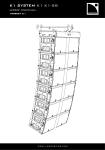
The KF860/VLA Series comprises two
high-output modules optimized to
create vertical line arrays. The Series
comprises two modules – the KF860
which features a 60° horizontal
coverage pattern, and the KF861
which features a 90° pattern for
nearfield coverage. Nominal vertical
coverage is 30° but the each array's true
vertical pattern is determined by the size and
configuration of the array as well as by digital signal
processor settings.
Each module contains 2x 15-in woofers, 2x horn-loaded
10-in mid frequency cone drivers, and 2x 2-in exit/75mm
voice coil compression drivers on constant directivity horns.
KF860 SERIES BACKGROUND
AND DESCRIPTION
The KF860/VLA Series was originally developed to help
solve specific problems for high-end entertainment industry
events that featured both live and broadcast audiences.
The key design parameters were minimal array size, high
output and broadband pattern control.
Part of the KF860 Series solution was the application
of configuration-specific digital signal processing (DSP)
to maintain pattern control over an exceptionally wide
bandwidth. Settings vary depending on the number of
modules in the array and the angle between adjacent
modules.Thus two crucial elements of any KF860 Series
application are accurately splaying the enclosures and
applying the correct DSP settings.
BUILDING AND PROCESSING
K F 8 6 0 S E R I E S A R R AY S
To maintain accurate and repeatable array angles, EAW
developed a unique, all-steel rigging system for the KF860
Series that eliminates guesswork. The steel rigging plates that
link modules together fit into steel-tubing brackets on each
end of the module and are secured with quick-release pins.
The reader will find a complete explanation of this rigging
system on pages 7 and 8 of this guide as well as in the
companion publication, KF860 Hardware Instructions.
EAW has developed appropriate settings for the MX8600
Close Coupled Digital Processor to control each of the
KF860 array configurations discussed in this guide. These
settings are available from the ftp (file transfer protocol)
section of EAW's website (www.eaw.com) or can be faxed as
text files for manual entry. These settings are appropriate to
the MX8600 and only the MX8600. Do not attempt to use
these settings in any other DSP unit. Contact EAW's
Application Support Group for more information.
HANGING AND AIMING
K F 8 6 0 S E R I E S A R R AY S
Hanging KF860 arrays requires the use of a dedicated
"bumper bar" developed for EAW by ATM, Inc. The bumper
bar accepts the top portion of the rigging plates at twelve
pre-configured locations.
The top module of any array will be aimed at an angle
determined by the bumper bar location selected and the size
and configuration of the array. As most application require
the array to be hung above the intended coverage area, the
bar has been designed to aim the array's output down.
However, the bar can be reversed to aim the array's output in
an upward direction. A chart indicating all possible angles
that can be obtained from the rigging system can be found
on page 8 of this guide.
EAW has developed a specially modified hand truck to
assist in rigging KF860 Series arrays. Specific instruction on
its use can be found at EAW's website or by contacting EAW
and requesting the KF860 Rigging Hardware Instructions.
T W O - H I G H K F 8 6 0 C O N F I G U R AT I O N
Typical Uses: Distributed ground-stacked clusters, delay
clusters on lifts or scaffolds.
Coverage: 20 degrees (specific angles determined by aiming)
Bumper Bar Trim Height (nominal): N/A
15°
Splay: The boxes are nominally splayed 10 degrees, which is
the tight-packed configuration. The coverage angle can be
opened up or tightened by splaying more or less than the
nominal 10 degrees. Ground-stacking note???
5°
Ground-Stacked Application Shown
Aiming: The cluster should be aimed so that the seam
between the two boxes points at the farthest seat. This
configuration is tuned for a 200 ft throw.
Processors: Only one EAW MX8600 processor is required.
• For manual entry – use file 2xKF860.TXT which may be
found at ftp://ftp.eaw.com/PPSTfiles/KF860.
• For ECORE – use file 2xKF860.EAC which may be found
at ftp://ftp.eaw.com/Process/MX8600
T H R E E - H I G H K F 8 6 0 C O N F I G U R AT I O N
5°
-10°
Typical Uses: Theatres
Coverage: +10 degrees to -60 degrees
Bumper Bar Trim Height (nominal): 22 ft
Splay: The three boxes are aimed +5, -10, & -35 degrees, so the
boxes should be rigged with 15 degree (upper to middle box),
and 25 degree (middle to downfill box) splays.
Aiming: The cluster should be aimed so that the top box
points at the highest seating area. This configuration is tuned
for a 100 ft throw to the farthest seat.
-35°
Processors: One processor should drive the upper two boxes.
This processor is referred to as “main” in the settings.
A second processor should drive the lowest box. This
processor is referred to as “downfill” in the settings.
• For manual entry – use file 3xKF860.TXT which may be
found at ftp://ftp.eaw.com/PPSTfiles/KF860.
• For ECORE – use file 3xKF860.EAC which may be found
at ftp://ftp.eaw.com/Process/MX8600
F O U R - H I G H K F 8 6 0 C O N F I G U R AT I O N
10°
0°
-15°
Typical Uses: Theatres and small arenas
Coverage: +15 degrees to -60 degrees
Bumper Bar Trim Height (nominal): 40 ft
Splay: The boxes are aimed +10, 0, -15, & -35 degrees, so the
boxes should be rigged with 10 degree (top to second box),
15 degree (second to third box), and 20 degree (third box to
downfill box) splays.
Aiming: The cluster should be aimed so that the top box
points at the highest seating area. This configuration is tuned
for a 150 ft throw to the farthest seat and maximized vertical
coverage.
Processors: One processor should drive the upper three
boxes. This processor is referred to as “main” in the settings.
A second processor should drive the lowest box.
This processor is referred to as “downfill” in the settings.
• For manual entry – use file 4xKF860.TXT which may be
found at ftp://ftp.eaw.com/PPSTfiles/KF860.
• For ECORE – use file 4xKF860.EAC which may be found
at ftp://ftp.eaw.com/Process/MX8600
-35°
FOUR-HIGH “SHED”
K F 8 6 0 C O N F I G U R AT I O N
0°
0°
-15°
-35°
Typical Uses: Sheds and small festivals.
Coverage: +2 degrees to -60 degrees
Bumper Bar Trim Height (nominal): 27 ft
Splay: The boxes are aimed 0, 0, -15, & -35 degrees, so the
boxes should be rigged with 0 degree (top to second box),
15 degree (second to third box), and 20 degree (third box
to downfill box) splays.
Aiming: The cluster should be aimed so that the top box
points at the farthest seat, or straight out for festivals.
This configuration is tuned for a 200 ft throw to the farthest
seat and cuts off very quickly above horizontal.
Processors: One processor should drive the upper three
boxes. This processor is referred to as “main” in the settings.
A second processor should drive the lowest box.
This processor is referred to as “downfill” in the settings.
• For manual entry – use file 4xKF860shed.TXT which may
be found at ftp://ftp.eaw.com/PPSTfiles/KF860.
• For ECORE – use file 4xKF860shed.EAC which may be
found at ftp://ftp.eaw.com/Process/MX8600
S I X - H I G H K F 8 6 0 C O N F I G U R AT I O N
-10°
-20°
-35°
5°
Typical Uses: Arenas
Coverage: +15 degrees to -60 degrees
Bumper Bar Trim Height (nominal): 40 ft
0°
Splay: The boxes are aimed +5, 0, -5, -10, -20, & -35 degrees,
so the boxes should be rigged with 5 degree (top to second
box), 5 degree (second to third box), 5 degree (third to fourth
box), 10 degree (fourth to fifth box), and 15 degree (fifth to
sixth box) splays.
-5°
Aiming: The cluster should be aimed so that the top box
points at the farthest seat. This configuration is tuned for a
300 ft throw to the farthest seat with maximized vertical
coverage.
Processors: One processor should drive the upper four
boxes. This processor is referred to as “main” in the settings.
A second processor should drive the two lowest boxes.
This processor is referred to as “downfill” in the settings.
NOTE: This is different from all of the smaller rigs, which
treat only the one bottom box as “downfill”.
• For manual entry – use file 6xKF860.TXT which may be
found at ftp://ftp.eaw.com/PPSTfiles/KF860.
• For ECORE – use file 6xKF860.EAC which may be found
at ftp://ftp.eaw.com/Process/MX8600
S I X - H I G H “ F E S T I VA L ”
K F 8 6 0 C O N F I G U R AT I O N
0°
0°
0°
-5°
-20°
-35°
Typical Uses: Festivals, large sheds
Coverage: +2 degrees to -60 degrees
Bumper Bar Trim Height (nominal): 27 ft
Splay: The boxes are aimed 0, 0, 0, -5, -20, & -35 degrees, so
the boxes should be rigged with 0 degree (top to second box),
0 degree (second to third box), 5 degree (third to fourth box),
15 degree (fourth to fifth box), and 15 degree (fifth to sixth
box) splays.
Aiming: The cluster should be aimed so that the top box
points at the highest/farthest seat or straight out for festivals.
This configuration is tuned for a 400 ft throw to the farthest
seat. The response falls off quickly above horizontal.
Processors: One processor should drive the upper four boxes.
This processor is referred to as “main” in the settings.
A second processor should drive the two lowest boxes.
This processor is referred to as “downfill” in the settings.
NOTE: This is different from all of the smaller rigs, which
treat only the one bottom box as “downfill”.
• For manual entry – use file6xKF860fest.TXT which may
be found at ftp://ftp.eaw.com/PPSTfiles/KF860.
• For ECORE – use file 6xKF860fest.EAC which may be
found at ftp://ftp.eaw.com/Process/MX8600
A C H I E V I N G VA R I O U S S P L AY A N G L E S
B E T W E E N K F 8 6 0 S E R I E S A R R AY M O D U L E S
CABINET'S BOTTOM
END BRACKET
Achieving the proper splay angles between KF860 Series array
modules is a relatively straight-forward procedure. As shown
in the illustrations below, each module's bottom end bracket
holes are marked to indicate the angle(s) they will produce
when the rigging plate is connected through them. Each rigging plate's holes are marked similarly.
To produce a given splay angle, simply align the proper
holes on the rigging plate with the proper holes on the module's bottom end bracket and insert quick release pins.
Each modules top end bracket is equipped with a springloaded cam device that accepts the bottom of the rigging
plate. The spring-loaded cams hold the rigging plate in place
while quick release pins are inserted to lock the plate in place.
Please consult EAW's KF860 Hardware Instructions for further
information.
ADJUSTABLE RIGGING
PLATE
K F 8 6 0 S E R I E S A R R AY M O D U L E B OT TO M E N D B R A C K E T H O L E S
Stage Left
Stage Right
5 DEG
5 DEG
0 DEG
0 DEG
10 TO 25 DEG
10 TO 25 DEG
H A N G I N G A N D A I M I N G K F 8 6 0 S E R I E S A R R AY S
A
E
B
F
G
C
H
D
KF860 Rigging Plate
The drawing above illustrates the KF860 Series bumper bar created for EAW by ATM
Flyware. By properly selecting the holes to which the top module is connected, users
can aim an array’s coverage over a wide range of angles.
Most applications require aiming the array in a downward direction. Thus the
bumper bar’s forward direction (to the left in the illustration above) allows a variety of
down angles. Should the user require aiming the array in an upward direction (such as
in sports arenas where upper decks are above the array height, simply set the bumper
bar in the revers direction (to the right in the illustration above).
Always use holes “A” and “G” on the rigging plate (as shown in the rigging plate
illustration) to connect the top module to the bumper bar. Hole “A” should always be
frontmost, no matter which direction the bumper bar is facing.
Please consult the chart below to determine the appropriate bumper bar position to
achieve your desired array angle. Note: the angles in the chart indicate the topmost
module’s centerline relative to the horizontal axis.
Pos. #1 Pos. #2 Pos. #3 Pos.#4
Pos.#5
Pos.#6
Pos.#7 Pos.#8
Pos.#9 Pos.#10
Pos.#11 Pos.#12
2x Standard
2x Reverse
1.0
-5.0
-1.0
-3.0
-3.0
-1.0
-5.5
1.0
-7.5
3.5
-9.5
5.5
-11.5
8.0
-13.5
10.0
-15.5
12.5
-18.0
15.0
-20.0
17.5
-22.0
20.0
3x Standard
3x Reverse
7.5
2.0
6.0
4.0
4.0
5.5
2.5
7.0
0.5
9.0
-1.0
11.0
-3.0
13.0
-4.5
15.0
-6.0
16.5
-8.0
18.5
-9.5
21.0
-11.0
23.0
4x Standard
4x Reverse
9.5
4.0
8.0
6.0
6.5
7.5
5.0
9.0
3.0
10.5
2.0
12.0
0.0
13.5
-1.0
15.5
-2.5
17.0
-4.0
19.0
-5.5
20.5
-7.0
22.5
4x Shed Stand. 4.5
4x Shed Rev.
0.0
3.0
1.0
1.5
2.5
0.5
4.0
-1.0
5.5
-2.5
7.0
-4.0
8.0
-5.0
9.5
-6.5
11.0
-7.5
12.5
-9.0
14.0
-10.5
15.5
6x Standard
6x Reverse
8.0
4.0
7.0
5.5
6.0
6.5
5.0
7.5
4.0
8.5
2.5
10.0
1.5
11.0
0.5
12.0
-0.5
13.0
-1.5
14.0
-2.5
15.5
-3.5
17.0
6x Fest. Stand.
6x Fest. Rev.
3.5
0.0
2.5
1.0
1.5
2.0
0.5
3.0
-0.5
4.0
-1.5
5.0
-2.5
6.0
-3.5
7.0
-4.5
8.0
-5.5
9.0
-6.5
10.0
-7.5
11.0
All angles are rounded to the nearest 1/2 degree
The Laws of Physics / The Art of Listening
One Main Street, Whitinsville, MA 01588 Tel: 800 992 5013 / 508 234 6158 Fax: 508 234 8251 Web: http://www.eaw.com
E U R O P E : E AW I N T E R N AT I O N A L LT D . ,
TEL: +44 1494 539090
FAX: +44 1494 539091