1
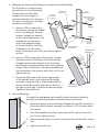
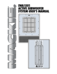
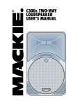
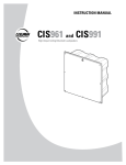
CLA37
Column Loudspeaker
INSTRUCTION MANUAL
1. SAFETY INSTRUCTIONS
1.
2.
3.
4.
5.
6.
7.
8.
9.
10.
11.
12.
13.
The exclamation point within an
Read these instructions.
equilateral triangle is intended to
alert the user of the presence of
Keep these instructions.
important operating and maintenance
Heed all warnings.
(servicing) instructions in the literature
accompanying the apparatus.
Follow all instructions.
Do not use this apparatus near water.
Clean only with a dry cloth.
Do not block any ventilation openings. Install in accordance with the manufacturer’s instructions.
Do not install near any heat sources such as radiators, heat registers, stoves, or other apparatus
(including amplifiers) that produce heat.
Only use attachments/accessories specified by the manufacturer.
Refer all servicing to qualified service personnel. Servicing is required when the apparatus
has been damaged in any way, such as liquid has been spilled or objects have fallen into the
apparatus, the apparatus has been exposed to rain or moisture, does not operate normally, or has
been dropped.
The entire sound system must be designed in compliance with the current standards and laws
regarding electrical systems.
When installing and using this apparatus, keep in mind the technical specifications indicated in the
dedicated section of the manual.
Exposure to high sound levels can cause permanent hearing loss. The sound pressure level which
leads to hearing loss varies considerably from one person to another, and depends on the duration
of exposure. The U.S. Government’s Occupational Safety and Health Administration (OSHA) has
established the maximum sound pressure levels that can be with stood without causing damage,
which are shown in the table below. According to the OSHA regulations, any exposure over the
maximum limits indicated in the table can reduce the hearing capacity of a person. To prevent
potentially dangerous exposure to high sound pressure levels, anyone subjected to such levels
must use suitable protection. When a EAW Commercial product capable of producing high sound
levels is being used, it is therefore necessary to wear ear plugs or protective earphones when
the limits shown in the table are exceeded. Consult the specifications provided in the instruction
manual to know the maximum sound pressure (SPL) the loudspeaker is capable of producing.
WARNING! This
equipment has been
designed to be installed
by qualified professionals
only! There are many factors
to be considered when
installing professional sound
reinforcement systems,
including mechanical and
electrical considerations, as
well as acoustic coverage and
performance. EAW Commercial
strongly recommends that this
equipment be installed only by
a professional sound installer or
contractor.
2 – CLA37
Duration per
day (hours)
Sound level
(dBA)
Typical example
Duo in a small club
8
90
6
92
4
95
3
97
2
100
1.5
102
1
105
0.5
110
0.25 or less
115
Subway train
Very loud classical music
Locomotive at 50 feet
Loudest parts at a rock concert
Part No. 0012959 Rev.A 09/2004
© 2004 LOUD Technologies Inc. All Rights Reserved.
14. Rigging Precautions: When mounting or suspending EAW Commercial loudspeaker
enclosures, it is essential that load ratings, rigging techniques, and special safety
considerations be appropriate for the installation. Use only the mounting/rigging points
on the loudspeaker enclosure intended for this purpose. The user must determine the load
requirements, dynamic loading, and any other contributing factors affecting the loudspeaker
installation. The user must determine the proper design factor for specific applications and
the required load rating of the connection to structure. Comply with all applicable federal,
state, and local regulations.
EAW Commercial strongly recommends the following rigging system practices:
• Documentation: Thoroughly document the mounting/rigging design with detailed
drawings and parts lists.
• Analysis: Have a licensed structural engineer or other qualified professional review and
approve the mounting/rigging design before its implementation.
• Installation: Use personnel experienced and qualified for mounting/rigging loudspeakers
in accordance with and in compliance with all federal, state and local regulations.
DANGER: Loudspeakers should be mounted or suspended only by persons with knowledge
of the proper hardware and rigging techniques. When stacking or pole-mounting
loudspeakers, be sure that they are stabilized and secured from falling over or being
accidentally pushed over. Failure to follow these precautions may result in damage to the
equipment, personal injury, or death.
TABLE OF CONTENTS
1. SAFETY INSTRUCTIONS........................................................ 2
2. INTRODUCTION....................................................................... 4
3. INSTALLATION ........................................................................ 5
4. CONNECTIONS........................................................................ 8
5. OPERATION.............................................................................. 10
6. SPECIFICATIONS..................................................................... 11
Dimensions.............................................................................. 11
Performance Graphs .............................................................. 12
7. TROUBLESHOOTING .............................................................. 13
8. SERVICE and MAINTENANCE............................................... 14
9. WARRANTY ............................................................................. 15
CLA37– 3
2. INTRODUCTION
Congratulations on the purchase of your new EAW Commercial loudspeaker. You now
own one of the finest professional audio products available – the result of exceptional
engineering and meticulous craftsmanship. Please read these instructions to get the
maximum performance from your new loudspeaker.
Each EAW Commercial loudspeaker is intended for professional use. The construction,
components, and hardware have been designed to provide robust, reliable performance for
its intended application. Please ensure that you fully understand its proper installation and
operation before use.
This manual describes the CLA37 frequency-shaded column loudspeaker. The CLA37 is an
economical solution for exceptional fidelity in speech reinforcement and background music
applications. It is especially suited for small to mid-sized spaces with excessive reverberation
or problematic sound reflections. The drivers and system voicing are designed to maximize
vocal range clarity and speech intelligibility, without compromising the broadband frequency
response required for pleasing music reproduction.
The CLA37 uses sophisticated, frequency shading to progressively shorten its acoustic
length with increasing frequency. The result is a well-behaved nominal vertical beamwidth
of 30 degrees to below 1 kHz that eliminates troublesome lobing. In the horizontal plane, the
drivers act as direct radiators. A waveguide loads the three center drivers to maintain the
nominal 120 degree beamwidth at high frequencies.
The included bracket allows setting the enclosure’s vertical angle for both wall-mounting
and suspension. An optional input panel has an integral transformer for 70 V or 100 V
distributed applications. The cross-ply laminated birch enclosure is available in either black
or white finish, and the powder-coated steel grille is foam-backed to hide the drivers from
view.
Features:
• Frequency-shaded, full-range,
column loudspeaker
• Seven high-quality 3-inch drivers
• 120 degree horizontal x 30
degree vertical nominal
beamwidth
• Passive crossover for
economical, single-amplifier
operation
• Optional 70 V / 100 V multi-tap
transformer
• Includes mounting/suspension
bracket
• Five-year warranty
4 – CLA37
Applications include:
•
•
•
•
•
•
Houses of Worship
Transportation Terminals
Museums
Theme Parks
Schools
Meeting Rooms
3. INSTALLATION
Unpacking and Inspection
Visually inspect the outside of the shipping carton and check for any damage. After
unpacking, if you find concealed damage to the loudspeaker, save the packing materials for
the carrier’s inspection, notify the carrier immediately, and file a shipping damage claim.
Although EAW Commercial will help in any way possible, it is always the responsibility of
the receiving party to file any shipping damage claim. The carrier will help prepare and file
this claim.
Mounting Precautions
The mounting bracket provided can be used for wall mounting the loudspeaker.
WARNING: Installation should only be done by an experienced technician.
Improper installation may result in damage to the equipment, injury or death. Make
sure that the loudspeaker is installed in a stable and secure way in order to avoid any
conditions that may be dangerous for persons or structures:
• Check to make sure that the support surface (e.g., wall, etc.) has the necessary
mechanical characteristics to support the weight of the loudspeaker without the
danger of it falling.
• Always use support elements suitable for the material of the wall that will support
the loudspeaker (e.g., screw anchors for bricks, screw anchors for cement, etc.). Due
to various construction methods and materials used today, the hardware for securing
the bracket to the mounting surface is not supplied. Consult a building professional
for the proper mounting hardware before mounting the bracket.
• Before suspending the loudspeaker, carefully check all the components to be used to
make sure there is no damage, deformation, corrosion and/or missing or damaged
parts that could reduce the safety of the installation.
• Consult a professional rigger or structural engineer prior to suspending loudspeakers
from a structure not intended for that use. Always know the working load limit of the
structure supporting the loudspeaker. Always make sure that the rigging hardware
minimum rating is at least five times the actual load.
• Avoid installing the loudspeaker in places exposed to harsh weather conditions.
CLA37– 5
Fly bracket and wall bracket mounting instructions
Follow these instructions to mount the fly bracket to the enclosure, hang the assembly
at various forward tilt angles, and attach the enclosure/fly bracket assembly to the wall
bracket. Make your speaker-wire connections before proceeding.
Warning: Installation should only be done
by an experienced technician. Improper
installation may result in damage to the
equipment, injury or death.
1. Mounting the Fly Bracket to the Enclosure:
SCREW 1/4 INCH-20
X 1.25 INCH LONG
HEX HEAD
2 PLACES
REUSE EXISTING
SCREW FROM TOP
a. Remove the screws from the top and bottom
of the enclosure.
b. Onto each of these two screws, place a lock
washer and a flat washer.
FLY
BRACKET
c. Insert a screw (with washers) through the
top hole of the fly bracket. Thread into the
enclosure’s top mounting hole.
d. Insert a screw (with washers) through the
bottom hole of the fly bracket. Thread into the
enclosure’s bottom mounting hole.
e. Angle the enclosure so it is at a right angle to
the fly bracket and tighten the two mounting
screws.
FLAT WASHER
1/4 INCH
2 PLACES
REUSE
EXISTING
SCREW FROM
BOTTOM
LOCK WASHER
1/4 INCH
2 PLACES
a. Support the enclosure/fly bracket
assembly from each side of the fly
bracket using one set of the paired
holes along its top and back.
b. The hardware for hanging the
enclosure/ fly bracket assembly is
not supplied. It is recommended
that you consult a rigging
professional to determine the
proper hardware to hang the
enclosure/fly bracket assembly.
FLYING ANGLES
(CABINET SHOWN
VERTICAL AT 0°)
9°
12°
16°
2. Hanging the Enclosure/Fly Bracket Assembly:
20°
22°
27°
30°
31°
32°
36°
40°
3. Mounting the Wall Bracket:
a. Mount the wall bracket to the desired surface (see picture on next page). The
hardware for securing the wall bracket to a mounting surface is not supplied. It
is recommended that you consult a rigging professional to determine the proper
hardware for mounting the bracket. Make sure the two holes nearest one end of the
wall bracket are toward the floor.
6 – CLA37
4. Mounting the Enclosure/Fly Bracket Assembly to the Wall Bracket:
The fly bracket is used to secure
the enclosure to the wall bracket.
The enclosure may be tilted
forward at various angles or
mounted vertically. For a forward
tilt, refer to the figure to the right
and these instructions:
CONNECTING
BRACKET
WALL
BRACKET
LOCK NUT
1/4 INCH-20
3 PLACES
a. Insert a 4.25 in screw with a
flat washer, through the middle
hole in the flange of the wall
bracket, through the channel
in the connecting bracket, and
through the second center
hole in the opposite flange
of the wall bracket. Onto the
threaded end of the screw,
place a flat washer and a lock nut. Do not tighten
just yet.
SCREW 1/4 INCH-20
X 4.25 INCH LONG
HEX HEAD
3 PLACES
Step 4a.
Step 4c.
Step 4b.
FLAT WASHER
1/4 INCH
6 PLACES
ENCLOSURE AND
FLY BRACKET
CONNECTING
BRACKET
4°
7°
10°
13°
16°
18°
22°
25°
b. Insert a 4.25 in screw with a flat washer, through
the bottom hole in the flange of the wall bracket,
through the horizontal channel in the fly bracket,
and through the second bottom hole in the opposite
flange of the wall bracket. Onto the threaded end of
the screw place a flat washer and a lock nut. Do not
tighten just yet.
c. Secure the other end of the connecting bracket
to the desired holes in the enclosure/fly bracket
assembly, using the 4.25 in screw/washer held in
place with the flat washer and lock nut. Refer to
the figure to the right to achieve the desired angle.
Tighten all three lock nuts.
25°
TILTING THE
ENCLOSURE
5. Vertical Mounting:
To mount the loudspeaker enclosure/fly bracket assembly vertically,
discard the connecting bracket, and follow these instructions:
1. Align the top hole in the wall bracket flange with the top rear holes in
the enclosure/fly bracket assembly, and insert a 4.25 in screw with a
flat washer.
2. Onto the threaded end of the screw, place a flat washer and a lock
nut. Do not tighten just yet.
3. Repeat step 4b above, to insert a screw into the wall bracket’s lowest
hole.
4. Tighten both lock nuts.
MOUNTING THE
ENCLOSURE VERTICALLY
CLA37– 7
Bracket Dimensions
Wall bracket
1.50"
(38.1)
4x
11 mm dia
3.50"
(89)
26.57"
(675)
Fly bracket
10.00"
(254)
3.43"
(87.16)
3.67"
(93.2)
25.57"
(649.6)
22.00"
(558.8)
0.70"
(17)
9x 8 mm dia)
1.00"
(25.4)
3.00"
(76.2)
6.00"
(152.4)
4.14"
(105.1)
25.08"
(637)
2x 8 mm dia
Connecting bracket
8.00"
(203.2)
NOTES:
UNLESS WHERE SPECIFIED:
1. DIMENSIONS ARE IN INCHES,
DIMENSIONS IN BRACKETS ARE MILLIMETERS.
2. DIMENSION TOLERANCE ± 0.03" (0.8 MM)
4. CONNECTIONS
WARNING: To prevent the risk of electric shock, do not connect the loudspeaker
with the amplifier switched on. The protective cover over the terminal strip
is a safety feature per CE requirements. Replace this cover after making the signal
connections.
1. Remove the insulating cover from the loudspeaker input
terminal strip.
2. The positive (+) input terminal of the loudspeaker connects
to the positive (+) output of your power amplifier.
3. The negative (–) terminal of the loudspeaker connects to
the negative (–) output of your power amplifier.
4. Using a small phillips screwdriver, secure the connections.
5. Replace the insulating cover over the loudspeaker input
terminal strip.
8 – CLA37
--
+
IN PUT
CAUTION:
SUSPENDING THIS SYSTEM SHOULD BE DONE BY QUALIFIED
TECHNICIANS FOLLOWING APPROPRIATE SAFETY STANDARDS
Loudspeaker Cables
• Use loudspeaker cables with a minimum
conductor size for the length you need, as
listed in these tables. This will minimize
power losses to less than 0.5 dB. The
cable lengths listed are “up to” lengths.
For in-between lengths, use the next larger
conductor gauge. Using larger than the
recommended conductor size is always
permissible. Using smaller than recommended
conductor size will result in higher power
losses.
Minimum AWG
4 ohm
8 ohm
18
10 ft
25 ft
16
25
50
14
25
75
12
50
125
10
100
200
Min Metric WG 4 ohm
8 ohm
12
3m
8m
14
8
15
8
25
15
40
30
60
• The recommended conductor gauges are
listed for AWG (American Wire Gauge) and
16
Metric WG (Metric Wire Gauge). Note that
20
smaller AWG numbers = larger conductors
25
and smaller Metric WG numbers = smaller
conductors. The Metric WG is equal to ten
times the nominal conductor diameter in millimeters.
• For cable lengths over 200 feet / 60 m at 8 ohms, and over 100 feet / 30 m at 4 ohms,
the conductor sizes needed for less than 0.5 dB power losses are rarely practical
for physical and cost reasons. As a practical compromise for these situations the
recommended conductor gauge is 10 AWG or 25 metric.
Precautions
• To prevent inductive phenomena causing humming or distortion, the speaker cables
should not be run together with electrical energy conductors, microphone cables, or
line-level audio lines.
• Use speaker cables that have markings to distinguish the polarity, such as insulation
or conductors of different colors.
• Before using the loudspeaker, carefully check that all the connections have been
made correctly to make sure there are no accidental short circuits that could cause
electrical sparks.
• Verify that the polarity of the connections to all of your loudspeakers are correct.
When more than one loudspeaker reproduces the same frequencies, but with
opposite polarity, there will be sound cancellations. Therefore, if any of the
loudspeakers are wired so that the +/- connection polarity is reversed with respect
to the others, incorrect reproduction will result. Most notably, the bass response will
suffer. This is especially true when loudspeakers are situated in adjacent positions
where the sound waves readily interact with each other.
CLA37– 9
5. OPERATION
Signal Processing
Sometimes external signal processing is desirable to “voice” the loudspeaker to
accommodate particular program material, less than optimum acoustics, feedback control, or
personal taste. For these purposes, use a suitable electronic signal processor. This can be as
simple as a 1/3 octave graphic equalizer or a fully capable DSP (digital signal processor) such
as the EAW Commercial DX810, or the EAW MX8750.
Choosing a Power Amplifier
There is no exact answer to the question of what amplifier size you should use for a
loudspeaker. The loudspeaker power rating in EAW Commercial’s specifications only means
it has passed a standard power test. This provides a rating that can be used as a point of
comparison with other loudspeakers. This rating does not necessarily correspond to the best
amplifier size to use nor is it a measure of a “safe” amplifier size to use. Rather, the amplifier
should be sized according to both the sound levels required and the type of audio signals
that will be reproduced. If you are unsure of how to determine this, consult with a qualified
professional or contact EAW Commercial Technical Support.
Preventing damage to the loudspeaker is a function of operating your audio system so
that the loudspeaker is not stressed beyond its design limits.
Operating Tips
• Do NOT drive any of your electronic equipment into clipping, particularly the power
amplifiers. This can easily damage the loudspeaker.
• If driven into clipping, even an amplifier with a power output rating lower than the
loudspeaker’s power rating can cause damage to a loudspeaker.
• Avoid sustained microphone feedback. This can quickly cause failure of highfrequency drivers.
• Avoid extreme boosts on equalizers as these can cause excessive input to the drivers
at the boosted frequencies. Generally, cutting frequencies is preferred to adjust the
frequency response.
• With appropriate signal processing, your loudspeaker should produce exceptionally
good sound. If it is used in a room with problematic acoustics, there is little you can
do to overcome the room problems with electronic adjustments. Your best solution
is careful placement and aiming of the loudspeaker so most of the sound is directed
only at the audience.
• Most EAW Commercial loudspeakers are capable of sound levels that can be
damaging to human hearing. Take precautions so that audiences are not exposed
to such levels. If you must expose yourself to these kinds of volume levels, wear
adequate hearing protection.
• Take care when moving or lifting the loudspeaker. Injury to you or damage to the
loudspeaker can result from careless handling.
10 – CLA37
6. SPECIFICATIONS
Model
Woofer
Woofer Loading
CLA37
3” x 7
Sealed
Operating Range (-10 dB)
140 Hz - 17.5 kHz
Horizontal Beamwidth - Nominal
120 degrees
Vertical Beamwidth - Nominal
30 degrees
Axial Sensitivity (whole space SPL)
96 dB, 140 Hz - 17.5 kHz
Peak Sensitivity (whole space SPL)
102 dB, 20 Hz to 20 kHz
Input Impedance - Nominal
8 ohm
Input Impedance - Minimum
6.3 ohm @ 500 Hz
Recommended High Pass Filter
≥ 125 Hz, 24 dB/octave
Butterworth
Power Handling
150 W, 35 V @ 8 ohm
Maximum SPL, Average
118 dB
Maximum SPL, Peak
124 dB
Height
Width
Depth
Dimension Tolerance
Weight
25.00 in/635.0 mm
6.00 in/152.4 mm
6.15 in/156.1 mm
± 0.1 in/2.5 mm
14.8 lb/6.7 kg
CLA37 Dimensions
6.00"
(152.4)
6.15"
(156.1)
6.00"
(152.4)
25.00"
(635.0)
0.65"
(16.4)
Bracket Mount
Point
1/4 - 20 threaded
4.37"
(111.1)
FRONT
SIDES
BACK
TOP &
BOTTOM
Dimensions are inches, dimensions in brackets are millimeters.
Tolerance: ± 0.1 in/2.5 mm
CLA37– 11
PERFORMANCE GRAPHS
CLA37 Impedance vs Frequency
Ohms
100
10
1
10
100
1000
10k 20k
Frequency (Hz)
CLA37 Axial Response vs Frequency
CLA37 Beamwidth vs Frequency
120
360
110
Degrees
SPL dB
100
90
80
100
10
Horizontal
Vertical
70
1
60
10
100
1000
10k 20k
100
Frequency (Hz)
1000
10k
20k
Frequency (Hz)
Disclaimer
EAW Commercial continually engages in research related to product improvement, new
materials, and production methods. Design refinements are introduced into existing products
without notice as a routine expression of that philosophy. For this reason, any current EAW
Commercial product may differ in some respect from its published description, but will
always equal or exceed the original design specifications unless otherwise stated.
“EAW Commercial” is a trademark of LOUD Technologies Inc.
All other brand names mentioned are trademarks or registered trademarks of their
respective holders, and are hereby acknowledged.
12 – CLA37
7. TROUBLESHOOTING
Loudspeaker difficulties usually fall into one of the following categories. The causes for
each are listed in the most likely order of probability.
No Sound or Low Output
• Loudspeaker cables or connectors are not wired correctly or are faulty. Check
all cabling, referring to these instructions for the correct connections. The best
way to check a suspect cable is to swap it with a known good cable. Check the
loudspeaker’s input panel to verify correct cable connections.
• Electronic equipment is not turned on, or the level controls are not adjusted properly.
Make sure that all equipment in the signal path is powered up, and that all controls
are set to appropriate levels for normal operation.
• Loudspeaker is not working. Connect the loudspeaker cable to a known good
loudspeaker, leaving all equipment set to the same levels. If the problem disappears,
the loudspeaker is probably not working. Contact EAW Commercial Technical Support
for appropriate troubleshooting.
Distorted Sound
• The power amplifier is clipping. The signal level is exceeding the limits of your
system and you must reduce the level.
• Other electronic equipment is being overdriven. Ensure that no equipment in the
signal chain is being over driven. For example: input(s) or summing bus in the mixing
console, equalizers, etc.
• Driver(s) not working properly. Contact EAW Commercial Technical Support for
appropriate troubleshooting.
Partial Sound (frequency band missing)
• Incorrect EQ settings in the electronic equipment. Ensure that all EQ settings and
filters on the mixing console, preamplifier, or other equipment are set for normal
operation. Ensure that level controls on electronic crossovers and associated
amplifiers are correctly set, and that all cables and connections for such equipment
are connected and working properly.
• Driver not working properly. Contact EAW Commercial Technical Support for
appropriate troubleshooting.
• The crossover network inside the loudspeaker is not working properly. Contact EAW
Commercial Technical Support for appropriate troubleshooting.
CLA37– 13
8. SERVICE and MAINTENANCE
Maintenance
Usually, your EAW Commercial loudspeaker will not require regular maintenance for
normal use. However, you can do several things to keep your loudspeaker in good operating
and cosmetic condition.
• Testing: Periodically test your loudspeaker for proper performance. A simple test is
to play a CD through it using well-defined, articulate, wide-range program material.
Listen to ensure all drivers are working properly and for any evidence of distortion or
other extraneous sounds. Test at several volume levels: very low, normal, and high.
• Mounting/Rigging: Any mounting or rigging hardware should be regularly inspected
for security, wear, deformation, corrosion, and any other circumstances that may
affect the load-handling capability. Immediately remove from service and replace any
hardware whose load-handling capability may be compromised.
• Cleaning: Cleaning the exterior of the enclosure will depend on the type of “dirt.”
Dust, food spills, or similar contaminants can usually be removed with a cloth
dampened with water, or a mild household cleaner. Avoid using any strong solvents
as this may damage the finish. Turn the amplifiers off before cleaning.
• Scratches or Dents in Wood Enclosures: Minor scratches on the enclosure can be
painted over with an outdoor latex paint, or simply a colored in with a “Sharpie” or
artist’s marking pen. More serious gouges or dents should be sanded out, filled with
wood putty, and repainted. Touch-up paint in pints and quarts is available through
EAW Commercial Technical Support.
Service
If your loudspeaker should require servicing, please follow these instructions:
1. Call EAW Commercial Tech Support at 1-888-337-7404, 7 am to 5 pm PST
(Monday-Friday), to verify the problem and obtain a Service Request Number. Be sure
to have the serial number of the unit when you call. You must have a Service Request
Number in order to obtain warranty service at the factory or at an authorized service
center. You can also email EAW Commercial Tech Support at:
[email protected]
2. Pack the unit in its original packaging. THIS IS VERY IMPORTANT. LOUD Technologies
is not responsible for any damage that occurs during shipping due to nonconventional packaging. Original packaging helps to minimize the possibility of
shipping damage.
3. Include a legible note stating your name, (no P.O. boxes), daytime phone number,
Service Request Number, and a detailed description of the problem, including how
we can duplicate it.
4. Write the Service Request Number in BIG BOLD PRINT on top of the box.
14 – CLA37
5. Tech Support will tell you where to ship the unit when you call for a Service Request
Number. We suggest insurance for all forms of cartage.
EAW Commercial Technical Support
Phone (USA/Canada)
888-337-7404
Phone
425-892-6503
Fax
425-485-1152
Address
One Main Street
Whitinsville, MA 01588
Web site
www.eawcommercial.com
e-mail
[email protected]
9. WARRANTY
Warranty: LOUD Technologies Inc. requires its authorized EAW Commercial distributors
abide by the following warranty terms for all EAW Commercial brand products (all dates
are from the date of delivery from an Authorized EAW Commercial Distributor to the end
user/installation site):
Loudspeakers – 5 years; Active Electronics – 5 years; Accessories – 2 years.
What Is Covered: Defects in workmanship and materials and against malfunctions. EAW
Commercial distributors must remedy all such defects and malfunctions without charge
for parts or labor if the warranty applies. Final determination of warranty coverage lies
solely with each authorized EAW Commercial distributor.
What Is Not Covered: This warranty does not extend to damage or malfunctions
resulting from, but not limited to, shipment, improper installation, misuse, neglect,
abuse, normal wear, accident, or to any product on which the serial number has been
modified or removed. Exterior defects in or damage to the exterior appearance are
specifically excluded from this warranty. EAW Commercial distributors shall not be liable
for incidental or consequential damages resulting from the use of EAW Commercial
products. Repairs and/or modifications by other than an Authorized EAW Commercial
Distributor automatically voids this warranty.
CLA37– 15
EAW Commercial | One Main Street | Whitinsville, MA 01588 USA
TEL toll free within US/Canada 888.337.7404 | TEL outside US 425.892.6503 | FAX 425.485.1152
www.eawcommercial.com
© 2004 LOUD Technologies Inc. All Rights Reserved. EAW Commercial is a registered trademark of LOUD Technologies Inc.