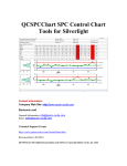
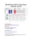
1
QCSPCChart SPC Control Chart Tools for Android Contact Information Company Web Site: http://www.quinn-curtis.com General Information: [email protected] Sales: [email protected] Technical Support Forum: http://www.quinn-curtis.com/ForumFrame.htm Revision Date 1/6/2014 Rev. 2.3 SPC Control Chart Tools for Android Documentation and Software Copyright Quinn-Curtis, Inc. 2014 Quinn-Curtis, Inc. Tools Tools for Android END-USER LICENSE AGREEMENT IMPORTANT-READ CAREFULLY: This Software End-User License Agreement ("EULA") is a legal agreement between you (either an individual or a single entity) and Quinn-Curtis, Inc. for the Quinn-Curtis, Inc. SOFTWARE identified above, which includes all Quinn-Curtis, Inc Android software (on any media) and related documentation (on any media). By installing, copying, or otherwise using the SOFTWARE, you agree to be bound by the terms of this EULA. If you do not agree to the terms of this EULA, do not install or use the SOFTWARE. If the SOFTWARE was mailed to you, return the media envelope, UNOPENED, along with the rest of the package to the location where you obtained it within 30 days from purchase. 1. The SOFTWARE is licensed, not sold. 2. GRANT OF LICENSE. (A) Developer License. After you have purchased the license for SOFTWARE, and have received the file containing the licensed copy, you are licensed to copy the SOFTWARE only into the memory of the number of computers corresponding to the number of licenses purchased. The primary user of the computer on which each licensed copy of the SOFTWARE is installed may make a second copy for his or her exclusive use on a portable computer. Under no other circumstances may the SOFTWARE be operated at the same time on more than the number of computers for which you have paid a separate license fee. You may not duplicate the SOFTWARE in whole or in part, except that you may make one copy of the SOFTWARE for backup or archival purposes. You may terminate this license at any time by destroying the original and all copies of the SOFTWARE in whatever form. (B) 30-Day Trial License. You may download and use the SOFTWARE without charge on an evaluation basis for thirty (30) days from the day that you DOWNLOAD the trial version of the SOFTWARE. The termination date of the trial SOFTWARE is embedded in the downloaded SOFTWARE and cannot be changed. You must pay the license fee for a Developer License of the SOFTWARE to continue to use the SOFTWARE after the thirty (30) days. If you continue to use the SOFTWARE after the thirty (30) days without paying the license fee you will be using the SOFTWARE on an unlicensed basis. Redistribution of 30-Day Trial Copy. Bear in mind that the 30-Day Trial version of the SOFTWARE becomes invalid 30-days after downloaded from our web site, or one of our sponsor’s web sites. If you wish to redistribute the 30-day trial version of the SOFTWARE you should arrange to have it redistributed directly from our web site If you are using SOFTWARE on an evaluation basis you may make copies of the evaluation SOFTWARE as you wish; give exact copies of the original evaluation SOFTWARE to anyone; and distribute the evaluation SOFTWARE in its unmodified form via electronic means (Internet, BBS's, Shareware distribution libraries, CD-ROMs, etc.). You may not charge any fee for the copy or use of the evaluation SOFTWARE itself. You must not represent in any way that you are selling the SOFTWARE itself. You must distribute a copy of this EULA with any copy of the SOFTWARE and anyone to whom you distribute the SOFTWARE is subject to this EULA. (C) Redistributable License. The standard Developer License permits the programmer to deploy and/or distribute applications that use the Quinn-Curtis SOFTWARE, royalty free. We cannot allow developers to use this SOFTWARE to create a graphics toolkit (a library or any type of graphics component that will be used in combination with a program development environment) for resale to other developers. If you utilize the SOFTWARE in an application program, or in a web site deployment, should we ask, you must supply QuinnCurtis, Inc. with the name of the application program and/or the URL where the SOFTWARE is installed and being used. 3. RESTRICTIONS. You may not reverse engineer, de-compile, or disassemble the SOFTWARE, except and only to the extent that such activity is expressly permitted by applicable law notwithstanding this limitation. You may not rent, lease, or lend the SOFTWARE. You may not use the SOFTWARE to perform any illegal purpose. 4. SUPPORT SERVICES. Quinn-Curtis, Inc. may provide you with support services related to the SOFTWARE. Use of Support Services is governed by the Quinn-Curtis, Inc. polices and programs described in the user manual, in online documentation, and/or other Quinn-Curtis, Inc.-provided materials, as they may be modified from time to time. Any supplemental SOFTWARE code provided to you as part of the Support Services shall be considered part of the SOFTWARE and subject to the terms and conditions of this EULA. With respect to technical information you provide to Quinn-Curtis, Inc. as part of the Support Services, Quinn-Curtis, Inc. may use such information for its business purposes, including for product support and development. QuinnCurtis, Inc. will not utilize such technical information in a form that personally identifies you. 5. TERMINATION. Without prejudice to any other rights, Quinn-Curtis, Inc. may terminate this EULA if you fail to comply with the terms and conditions of this EULA. In such event, you must destroy all copies of the SOFTWARE. ii 6. COPYRIGHT. The SOFTWARE is protected by United States copyright law and international treaty provisions. You acknowledge that no title to the intellectual property in the SOFTWARE is transferred to you. You further acknowledge that title and full ownership rights to the SOFTWARE will remain the exclusive property of Quinn-Curtis, Inc. and you will not acquire any rights to the SOFTWARE except as expressly set forth in this license. You agree that any copies of the SOFTWARE will contain the same proprietary notices which appear on and in the SOFTWARE. 7. EXPORT RESTRICTIONS. You agree that you will not export or re-export the SOFTWARE to any country, person, entity, or end user subject to U.S.A. export restrictions. Restricted countries currently include, but are not necessarily limited to Cuba, Iran, Iraq, Libya, North Korea, Sudan, and Syria. You warrant and represent that neither the U.S.A. Bureau of Export Administration nor any other federal agency has suspended, revoked or denied your export privileges. 8. NO WARRANTIES. Quinn-Curtis, Inc. expressly disclaims any warranty for the SOFTWARE. THE SOFTWARE AND ANY RELATED DOCUMENTATION IS PROVIDED "AS IS" WITHOUT WARRANTY OF ANY KIND, EITHER EXPRESS OR IMPLIED, INCLUDING, WITHOUT LIMITATION, THE IMPLIED WARRANTIES OR MERCHANTABILITY, FITNESS FOR A PARTICULAR PURPOSE, OR NONINFRINGEMENT. THE ENTIRE RISK ARISING OUT OF USE OR PERFORMANCE OF THE SOFTWARE REMAINS WITH YOU. 9. LIMITATION OF LIABILITY. IN NO EVENT SHALL QUINN-CURTIS, INC. OR ITS SUPPLIERS BE LIABLE TO YOU FOR ANY CONSEQUENTIAL, SPECIAL, INCIDENTAL, OR INDIRECT DAMAGES OF ANY KIND ARISING OUT OF THE DELIVERY, PERFORMANCE, OR USE OF THE SUCH DAMAGES. IN ANY EVENT, QUINN-CURTIS’S LIABILITY FOR ANY CLAIM, WHETHER IN CONTRACT, TORT, OR ANY OTHER THEORY OF LIABILITY WILL NOT EXCEED THE GREATER OF U.S. $1.00 OR LICENSE FEE PAID BY YOU. 10. U.S. GOVERNMENT RESTRICTED RIGHTS. The SOFTWARE is provided with RESTRICTED RIGHTS. Use, duplication, or disclosure by the Government is subject to restrictions as set forth in subparagraph (c)(1)(ii) of The Rights in Technical Data and Computer SOFTWARE clause of DFARS 252.227-7013 or subparagraphs (c)(i) and (2) of the Commercial Computer SOFTWARE- Restricted Rights at 48 CFR 52.227-19, as applicable. Manufacturer is: Quinn-Curtis, Inc., 18 Hearthstone Dr., Medfield MA 02052 USA. 11. MISCELLANEOUS. If you acquired the SOFTWARE in the United States, this EULA is governed by the laws of the state of Massachusetts. If you acquired the SOFTWARE outside of the United States, then local laws may apply. Should you have any questions concerning this EULA, or if you desire to contact Quinn-Curtis, Inc. for any reason, please contact Quinn-Curtis, Inc. by mail at: Quinn-Curtis, Inc., 18 Hearthstone Dr., Medfield MA 02052 USA, or by telephone at: (508)359-6639, or by electronic mail at: [email protected] Table of Contents 1. Introduction..................................................................................................................................1 What's New in Rev. 2.3...............................................................................................................1 What's New in Rev. 2.2...............................................................................................................2 Tutorials.......................................................................................................................................2 SPC Control Chart Tools for Android Background.....................................................................2 Differences between the QCSPCChart for Java (JAV-SPC2-DEVR) and QCSPCChart for Android (AND-SPC2-DEVR).....................................................................................................4 Customer Support........................................................................................................................5 Quinn-Curtis SPC (Statistical Process Control) Software...........................................................5 QCSPCChart for Android Dependencies.....................................................................................7 Directory Structure of QCSPCChart for Android........................................................................8 Chapter Summary......................................................................................................................10 2. Standard SPC Control Charts ....................................................................................................12 Variable Control Charts.............................................................................................................13 Attribute Control Charts............................................................................................................30 Other Important SPC Charts......................................................................................................37 3. Class Architecture of the SPC Control Chart Tools for Android Class Library .......................43 Major Design Considerations....................................................................................................43 SPC Control Chart Tools for Android Class Summary.............................................................45 SPC Control Chart Tools for Android Class Hierarchy.............................................................46 QCSPCChart Classes................................................................................................................47 4. QCChart2D for Android Class Summary..................................................................................60 Chart Window Classes...............................................................................................................61 Data Classes...............................................................................................................................61 Scale Classes..............................................................................................................................62 Coordinate Transform Classes...................................................................................................63 Auto-Scaling Classes.................................................................................................................65 Chart Object Classes..................................................................................................................66 Touch Interaction Classes........................................................................................................105 File Rendering Classes............................................................................................................107 Miscellaneous Utility Classes..................................................................................................107 5. SPC Control Data and Alarm Classes......................................................................................110 Class SPCControlChartData ...................................................................................................110 Control Limit Alarms...............................................................................................................125 Control Limit Alarm Event Handling......................................................................................127 SPCSampledValueRecord ......................................................................................................129 SPCCalculatedValueRecord ...................................................................................................129 SPCProcessCapabilityRecord .................................................................................................129 SPCGeneralizedTableDisplay..................................................................................................130 6. SPC Variable Control Charts...................................................................................................131 Time-Based and Batch-Based SPC Charts..............................................................................133 Creating a Batch-Based Variable Control Chart......................................................................190 Changing the Batch Control Chart X-Axis Labeling Mode....................................................193 Changing Default Characteristics of the Chart........................................................................197 7. SPC Attribute Control Charts..................................................................................................201 Time-Based and Batch-Based SPC Charts..............................................................................202 Changing the Batch Control Chart X-Axis Labeling Mode....................................................244 8. Named and Custom Control Rule Sets....................................................................................251 Western Electric (WECO) Rules.............................................................................................251 Western Electric (WECO) Rules.............................................................................................252 Nelson Rules............................................................................................................................253 AIAG Rules.............................................................................................................................253 Juran Rules...............................................................................................................................253 Hughes Rules...........................................................................................................................254 Gitlow Rules............................................................................................................................254 Duncan Rules .....................................................................................................................254 Westgard Rules .......................................................................................................................255 Control Rule Templates...........................................................................................................255 Implementing a Named Rule Set.............................................................................................260 Modifying Existing Named Rules...........................................................................................264 Creating Custom Rules Sets Based on Named Rules..............................................................265 Creating Custom Rules Sets Based on a Template..................................................................266 iv Creating Custom Rules Not Associated With Sigma Levels...................................................268 Control Limit Alarm Event Handling......................................................................................274 9. Frequency Histogram, Pareto Diagram and Normal-Probability Charts.................................277 Frequency Histogram Chart.....................................................................................................277 Probability Plots.......................................................................................................................284 Pareto Diagrams.......................................................................................................................288 10. File Rendering Classes...........................................................................................................293 Capturing the Chart as a Buffered Image................................................................................293 11. Regionalization for non-USA English Markets.....................................................................296 12. Creating, Compiling and Running the QCSPCChart Programs............................................307 Eclipse......................................................................................................................................307 Where at the examples?...........................................................................................................307 Creating an Android Project....................................................................................................309 Index............................................................................................................................................333 SPC Control Chart Tools for Android 1. Introduction What's New in Rev. 2.3 All of the new features found in the 2.3 version of QCSPCChart were added to QCChart2D primarily a new collection of event based charting classes. None of these routines have been used in the QCSPCChart software. Event-Based Charting A new set of classes have been added in support of new, event-based plotting system. In eventbased plotting, the coordinate system is scaled to the number of event objects. Each event object represents an x-value, and one or more y-values. The x-value can be time based, or numeric based, while the y-values are numeric based. Since an event object can represent one or more yvalues for a single x-value, it can be used as the source for simple plot types (simple line plot, simple bar plot, simple scatter plot, simple line marker plot) and group plot types (open-highlow-close plots, candlestick plots, group bars, stacked bars, etc.). Event objects can also store custom data tooltips, and x-axis strings. The most common use for event-based plotting will be for displaying time-based data which is discontinuous: financial markets data for example. In financial markets, the number trading hours in a day may change, and the actual trading days. Weekends, holidays, and unused portions of the day can be excluded from the plot scale, producing continuous plots of discontinuous data. The following classes have been added to the software in support of event-based charting. • • • • • • • • • ChartEvent - A ChartEvent object stores the position value, the time stamp, y-values, and custom strings associated with the event. EventArray - A utility array class used to store ChartEvent objects EventAutoScale – An auto-scale class used by the EventCoordinates class. EventAxis - Displays an axis based on an EventCoordinates scale EventAxisLabels – Displays the string labels labeling the tick marks of an EventAxis EventCoordinates – Event coordinates define a coordinate system based on the the attached Event datasets EventGroupDataset – A group dataset which uses ChartEvent objects as the source of the data. It is used to feed data into the group plotting routines. EventScale – An event scale class used to convert between event coordinates and device coordinates. EventSimpleDataset - A simple dataset which uses ChartEvent objects as the source of the data. It is used to feed data into the simple plotting routines. 2 Introduction What's New in Rev. 2.2 • • • • • Three new control charts – Moving Average/Moving Range (MAMR), Moving Average/Moving Sigma (MAMS) and the Number Defects per Million (DPMO). See Chapter 6 (SPC Variable Control Charts) and Chapter 7 (SPC Attribute Control Charts). Direct support for additional control rule sets – Nelson, AIAG, Juran, Hughes, Gitlow, Westgard, and Duncan, in addition to the WE (Western Electric) and Supplemental Rules. See Chapter 8 ( Named and Custom Control Rule Sets). Create custom sets of control rules, using any rule from any of the standard named control rule sets. See Chapter 8 ( Named and Custom Control Rule Sets). Define custom control rules: based any of our predefined control rule templates See Chapter 8 ( Named and Custom Control Rule Sets). Regionalization – All strings used in the software have been moved to a static class which can be initialized at runtime with country specific strings. See Chapter 11 ( Regionalization for non-USA English Markets). Tutorials Chapter 12 is a tutorial that describes how to get started running the example programs that come with the SPC Control Chart Tools for Android charting software. It also includes a tutorial that describes how to use the software to create charts for Android applications. SPC Control Chart Tools for Android Background In a competitive world environment, where there are many vendors selling products and services that appear to be the same, quality, both real and perceived, is often the critical factor determining which product wins in the marketplace. Products that have a reputation for higher quality command a premium, resulting in greater market share and profit margins for the manufacturer. Low quality products not only take a big margin hit at the time of sale, but also taint the manufacturer with a reputation that will hurt future sales, regardless of the quality of future products. Users have a short memory. A company’s quality reputation is only as good as the quality of its most recent product. The measurement, control and gradual improvement of quality is the goal of all quality systems, no matter what the name. Some of the more common systems are known as SCC (Statistical Quality Control) Quality Engineering, Six-Sigma, TQM (Total Quality Management), TQC (Total Quality Control), TQA (Total Quality Assurance) and CWQC (Company- Wide Quality Control). These systems work on the principle that management must integrate quality into the basic structure of the company, and not relegate it to a Quality Control group within the company. Historically, most of the innovations in quality systems took place in the 20th century, with pioneering work carried out by Frederick W. Taylor (Principles of Scientific Management), Henry Ford (Ford Motor), W. A. Shewhart (Bell Labs), W. E. Deming (Department of Agriculture, War department, Census Bureau), Dr. Joseph M. Juran (Bell Labs), and Dr. Armand V. Feigenbaum among others. Most quality control engineers are familiar with the story of how the statistical quality control pioneer, W. E. Deming, frustrated that US manufacturers only gave lip service to quality, took the quality system he developed to Japan, where it was embraced with Introduction 3 almost religious zeal. Japananese industry considers Deming a national hero, where his quality system played a major role in the postwar expansion of the Japanese economy. Twenty to thirty years after Japan embraced his methods, Deming found a new audience for his ideas at US companies that wanted to learn Japanese methods of quality control. All quality systems use Statistical Process Control (SPC) to one degree or another. SPC is a family of statistical techniques used to track and adjust the manufacturing process in order to produce gradual improvements in quality. While it is based on sophisticated mathematical analysis involving sampling theory, probability distributions, and statistical inferences, SPC results can usually be summarized using simple charts that even management can understand. SPC charts can show how product quality varies with respect to critical factors that include things like batch number, time of day, work shift personal, production machine, and input materials. These charts have odd names like X-Bar R, Median Range, Individual Range, Fraction Number Non-Conforming, and NP. The charts plot some critical process variable that is a measurement of product quality and compares it to predetermined limits that signify whether or not the process is working properly. Initially, quality control engineers create all SPC charts by hand. Data points were painstakingly gathered, massaged, summed, averaged and plotted by hand on graph paper. It is still done this way in many cases. Often times it is done by the same factory floor personal who control the process being measured, allowing them to “close the loop” as quickly as possible, correcting potential problems in the process before it goes out of control. Just as important, SPC charts tell the operator when to leave the process alone. Trying to micro-adjust a process, when the process is just exhibiting normal random fluctuations in quality, will often drive the process out of control faster than leaving it alone. The modern tendency is to automate as much of the SPC chart creation process as possible. Electronic measuring devices can often measure quality in real-time, as items are coming off the line. Usually some form of sampling will be used, where one of every N items is measured. The sampled values form the raw the data used in the SPC chart making process. The values can be entered by hand into a SPC chart making program, or they can be entered directly from a file or database connection, removing the potential for transcription errors. The program displays the sampled data in a SPC chart and/table where the operator or quality engineer can make a judgment about whether or not the process is operating in or out of control. Usually the SPC engineer tasked with automating an existing SPC charting application has to make a decision about the amount of programming he wants to do. Does he purchase an application package that implements standard SPC charts and then go about defining the charts using some sort of menu driven interface or wizard. This is probably the most expensive in terms of up front costs, and the least flexible, but the cheapest in development costs since a programmer does not have to get involved creating the displays. Another choice is to use a general purpose spreadsheet package with charting capability to record, calculate, and display the charts. This is probably a good choice if your charting needs are simple, and you are prepared to write complicated formulas as spreadsheet entries, and your data input is not automated. Another choice is writing the software from scratch, using a charting toolkit like our QCChart2D software as the base, and creating custom SPC charts using the primitives in the toolkit. This is cheaper up front, but may be expensive in terms of development costs. Often times the third 4 Introduction option is the only one available because the end-user has some unique requirement that the prepackaged software can’t handle, hence everything needs to programmed from scratch. Differences between the QCSPCChart for Java (JAV-SPC2-DEVR) and QCSPCChart for Android (AND-SPC2-DEVR). In terms of the source code for the chart building portions of your program, there are only a few difference you need to be concerned with. QCChart2D/QCSPCChart for Java QCChart2D/QCSPCChart for Android Font ChartFont Unlike Java AWT Graphics, the Android graphics framework does not include a single class which encapsulates font characteristics. Instead, the Android TextPaint class has a handful of font properties which are used instead. We have created a ChartFont class, analogous to the Java AWT Font class, which we use to specify the font typeface, font size and font style properties. The QCChart2D classes which use a text font require a reference to an object of ChartFont. See Chapter 8. Color ChartColor Android graphics do not use a Color class to pass color arguments. Instead, colors are represented using an int (a 32-bit integer) which supports standard RGB colors with alpha blending (transparency). There is an android.graphics.Color class, which contains static methods useful in defining integer color values. Oddly, the 2.2 version of Android Java only includes the most basic set of name color constants. In order maintain a degree of compatibility with other versions of the software, we chose to implement simple color class which is a wrapper around a 32-bit integer holding a n Android color value. The ChartColor class also makes public over 140 static methods which will return a named color, such as ChartColor.BLUE, or ChartColor.SPRINGGREEN. Also, it includes constructors and set methods, analogous to the standard Java awt.color class, for creating colors based on rgb and alpha values. See Chapter 6. ChartMouseListener ChartTouchListener Android does not include mouse listeners like regular Java. Instead, Android uses touch listeners, which are similar in function, in that there are touch down, move, drag and release methods. We attempt to duplicate the mouse user interface of the original Java software using touch equivalent routines. All of our mouse user interface classes now derive from ChartTouchListener. This includes ButonTouchArea, ChartZoom, DataCursor, DataToolTip, FindObj, MagniView, MoveCoordinates, MoveData, MoveObj, and ScrollTouchArea. The most important different to remember is that there are no button selectors with touch listeners. So in order to keep the touch listeners from interfering with one another, it is best to have only one active at a time. Introduction 5 Shapes and paths GPath The GPath class was created to overcome a weakness of the Android Path class. When you use the Android Path class, you cannot read back out the values of the Path. So if you write routines which accept Android Path objects as parameters, you are not able to read the coordinate values of the Path, something some of our classes must be able to do in order to appropriately transform the data. So we created or own path class, named GPath, which allow the construction of simple paths, and which maintains its own, accessible display list of coordinate values. Customer Support Use our forums at http://www.quinn-curtis.com/ForumFrame.htm for customer support. Please, do not post questions on the forum unless you are familiar with this manual and have run the examples programs provided. We try to answer most questions by referring to the manual, or to existing example programs. We will always attempt to answer any question that you may post, but be prepared that we may ask you to create, and send to us, a simple example program. The program should reproduce the problem with no, or minimal interaction, from the user. You should strip out of any code not directly associated with reproducing the problem. You can use either your own example or a modified version of one of our own examples. Quinn-Curtis SPC (Statistical Process Control) Software We have created a library of SPC routines that represents an intermediate solution. Our SPC software still requires an intermediate level programmer, but it does not require advanced knowledge of SPC or of charting. Built on top our QCChart2D, it implements templates and support classes for the following SPC charts and control limit calculations. Variable Control Charts Templates Fixed sample size subgroup control charts X-Bar R – (Mean and Range Chart) X-Bar Sigma (Mean and Sigma Chart) Median and Range (Median and Range Chart) X-R (Individual Range Chart) EWMA (Exponentially Weighted Moving Average Chart) MA (Moving Average Chart) MAMR (Moving Average / Moving Range Chart) MAMS (Moving Average / Moving Sigma Chart) CuSum (Tabular Cumulative Sum Chart) Variable sample size subgroup control charts X-Bar Sigma (Mean and Sigma Chart) 6 Introduction Attribute Control Charts Templates Fixed sample size subgroup control charts p Chart (Fraction or Percent of Defective Parts) np Chart (Number of Defective Parts) c-Chart (Number of Defects ) u-Chart (Number of Defects per Unit ) Number Defects per Million (DPMO) Variable sample size subgroup control charts p Chart (Fraction or Percent of Defective Parts) u-Chart (Number of Defects per Unit ) Analysis Chart Templates Frequency Histograms Probability Charts Pareto Charts SPC Support Calculations Array statistics (sum, mean, median, range, standard deviation, variance, sorting) SPC Control Limit Calculations High and low limit control calculations for X-Bar R, X-Bar Sigma, Median and Range, X-R, p, np, c and u charts SPC Process Capability Calculations Variable Control Charts include Cp, Cpl, Cpu, Cpk, Cpm, Pp, Ppl, Ppu, and Ppk process capability statistics SPC Control Named Rule Sets Western Electric (WECO) Runtime and Supplemental Rules Nelson AIAG Juran Hughes Gitlow Duncan Westgard The SPC Control Chart Tools for Android is a family of templates that integrate the QCChart2D charting software with tables, data structures and specialized rendering routines used for the static and dynamic display of SPC charts. The SPC chart templates are preprogrammed classes that create, manage and display the graphs and tables corresponding to major SPC control chart types. Each template can be further customized using method and properties. The programmers can customize the plot objects created in the template, allowing tremendous flexibility in the look of the SPC charts. Like the QCChart2D software, the SPC Control Chart Tools for Android uses the graphics features found in the Android API. Starting with Version 2.1, Android has a set of graphics classes providing programming tools as powerful as the Java API routines. Features found in the Android 2.1 API and used in com.quinncurtis.spcchartAndroid package include the following. Arbitrary line thickness and line styles for all lines. Introduction 7 Gradients, fill patterns and color transparency for solid objects. Image output support Improved font support for a large number of fonts, using a variety of font styles, size and rotation attributes. Advanced matrix support for handling 2D transformation. QCSPCChart for Android Dependencies The com.quinncurtis.spcchartAndroid and com.quinncurtis.chart2dAndroid packages are self-contained. They use only standard classes that ship with the Android 2.0 API. The software uses the major Android packages listed below. Package android.graphics The andriod.graphics package is the core of Android graphics system. It provides low level graphics tools such as canvases, color filters, points, and rectangles that let you handle drawing to the screen directly. The android.graphics classes most often used in the Quinn-Curtis chart2dandroid classes are the Canvas, Color, and Bitmap, Matrix, TypeFace and Path classes. . Class android.graphics.Bitmap Bitmap objects from various sources, including files, streams, and byte-arrays. Class android.graphics.Color The Color class defines methods for creating and converting color ints. Class android.graphics.Matrix The Matrix class holds a 3x3 matrix for transforming coordinates. Class android.graphics.Canvas The Canvas class holds the "draw" calls. Class android.graphics.Path The Path class encapsulates compound (multiple contour) geometric paths consisting of straight line segments, quadratic curves, and cubic curves. Class android.graphics.TypeFace The Typeface class specifies the typeface and intrinsic style of a font. 8 Introduction Package android.view Provides classes that expose basic user interface classes that handle screen layout and interaction with the user. Package java.io.* This package provides classes for file i/o and serialization. Directory Structure of QCSPCChart for Android The SPC Control Chart Tools for Android class library uses the standard directory structure also used by the QCChart2D software. It adds the spcchartAndroid directory structure under the Quinn-Curtis\Android\com\quinn-curtis folder. For a list of the folders specific to QCChart2D, see the manual for QCChart2D, QCChart2DAndroidManual.pdf. Drive: Quinn-Curtis\ - Root directory android\ - Quinn-Curtis Android based products directory docs\ - Quinn-Curtis Android related documentation directory lib\ - Quinn-Curtis Android related compiled libraries and components directory chart2dAndroid\ – QCChart2D specific spcchartAndroid\ - QCSPCChart specific Examples\ - examples directory FrequencyHistogram – a simple frequency histogram example using the FrequencyHistogramChart class BatchAttributeControlCharts - a collection of batch attribute control charts, including n, np, c, and u charts using the SPCBatchAttributeControlChart class. BatchVariableControlCharts - a collection of batch variable control charts, including X-Bar R, X-Bar Sigma, Median Range, and X-R charts using the SPCBatchVariableControlChart class. Introduction 9 TimeAttributeControlCharts - a collection of time attribute control charts, including n, np, c, and u charts using the SPCTimeAttributeControlChart class. TimeVariableControlCharts BatchVariableControlCharts - a collection of time variable control charts, including X-Bar R, X-Bar Sigma, Median Range, and X-R charts using the SPCTimeVariableControlChart class. MiscTimeBasedControlCharts - a collection of time variable control charts, including EWMA, MA and CuSum charts using the SPCTimeVariableControlChart class. MiscBatchBasedControlCharts - a collection of batch variable control charts, including EWMA, MA and CuSum charts using the SPCTimeVariableControlChart class. ProbabilityPlot - a probability chart using the ProbabilityChart class. ParetoDiagram - a Pareto diagram chart using the ParetoChart class. RulesRulesRules - a collection of control charts demonstrating the the use of named (WECO, Nelson, AIAG, Juran, Hughes, Duncan, Westgard, and Gitlow) and custom rule sets. SPCApplication1 – A simple X-Bar R example program, using SPCTimeVariableControlChart, used in the tutorial. WERulesVariableControlCharts - a collection of using the WE rules with SPCTimeVariableControlChart charts, including X-Bar R, X-Bar Sigma, Median Range, and X-R VariableSampleSizeControlCharts - a collection of the variable control (X-Bar Sigma), and attribute control (p- and u-charts) that support variable sample subgroup sizes. SPC Control Chart Tools for Android class library uses the QCChart2D licensing system. There are two main versions: the 30-day trial version and the developer version. The different versions are summarized below. Trial Version 10 Introduction The trial version of QCSPCChart for Android is downloaded as a zip file named Trial_QCSPCChartAndroidR22x.zip. The trial version displays a large, transparent overlay in the center of the screen, designating that it is a trial version. It will time out and be unusable at some point after the 30 days trial period. Developer Version The developer version of QCSPCChart for Android is downloaded as a zip file, name something similar to ANDSPCChartDEV1R2x1x353x1.zip. The developer version does not time out and you can use it to create application programs that you can distribute royalty free. You can download free updates for a period of 2-years. When you placed your order, you were e-mailed download link(s) that will download the software. Those download links will remain active for at least 2 years and should be used to download current versions of the software. After 2 years you may have to purchase an upgrade to continue to download current versions of the software Chapter Summary The remaining chapters of this book discuss the SPC Control Chart Tools for Android package designed to run on any hardware that has a Android runtime installed on it. Chapter 2 presents a summary of the standard SPC control charts that can be created using the software. Chapter 3 presents the overall class architecture of the SPC Control Chart Tools for Android and summarizes all of the classes found in the software. Chapter 4 summarizes the important QCSPCChart classes that you must be familiar with in order to customize advanced features of the SPC Control Chart Tools for Android software. Chapter 5 describes the classes that hold SPC control chart data and control limit alarms. Chapter 6 describes how the SPCTimeVariableControlChart and SPCBatchVariableControlChart classes create common variable control charts: X-Bar R, Median and Range, X-Bar Sigma and X-R charts. Chapter 7 describes how the SPCTimeAttributeControlChart and SPCBatchAttributeControlChart classes create common attribute control charts: p-, np-, cand u-charts. Chapter 8 describes how to implement the named control rules (WECO, Nelson, AIAG, Juran, Hughes, Gitlow, Westgard, and Duncan) control rules. It also describes how to implement custom rules sets, and how to define your own rules using our standardized templates Introduction 11 Chapter 9 describes how the FrequencyHistogramChart, ParetoChart and ProbabilityChart classes create ancillary SPC charts. Chapter 10 describes how to save the SPC charts to image files.. Chapter 11 describes to regionalize the strings used in the software. Chapter 12 is a tutorial that describes how to run the demos, and how to use SPC Control Chart Tools for Android to create Android Applications. 2. Standard SPC Control Charts There are many different types SPC control charts. Normally they fall into one of two major classifications: Variable Control Charts, and Attribute Control Charts. Within each classification, there are many sub variants. Often times the same SPC chart type has two or even three different names, depending on the software package and/or the industry the chart is used in. We have provided templates for the following SPC control charts: Variable Control Charts Fixed sample size subgroup control charts X-Bar R – (Mean and Range Chart) X-Bar Sigma (Mean and Sigma Chart) Median and Range (Median and Range Chart) X-R (Individual Range Chart) EWMA (Exponentially Weighted Moving Average Chart) MA (Moving Average Chart) MAMR (Moving Average / Moving Range Chart) MAMS (Moving Average / Moving Sigma Chart) CuSum (Tabular Cumulative Sum Chart) Variable sample size subgroup control charts X-Bar Sigma (Mean and Sigma Chart) Attribute Control Charts Fixed sample size subgroup control charts p Chart (Fraction or Percent of Defective Parts) np Chart (Number of Defective Parts) c-Chart (Number of Defects ) u-Chart (Number of Defects per Unit ) Number Defects per Million (DPMO) Variable sample size subgroup control charts p Chart (Fraction or Percent of Defective Parts) u-Chart (Number of Defects per Unit ) Time-Based and Batch-Based SPC Charts We have further categorized Variable Control charts and Attribute Control Charts as either time- or batch- based. While you may not find this distinction in SPC textbooks (we didn’t), it makes sense to us as charting experts. Quality engineers use time-based SPC charts when data is collected using a subgroup interval corresponding to a specific time interval. They use batchbased SPC charts when the data subgroup interval is a sequential batch number that does not correspond to a uniform time interval. The major difference in these two types of SPC charts is Standard SPC Control Charts 13 the display of the x-axis. Variable control charts that sample using a uniform time interval will generally use a time-based x-axis, with time/date axis labels. Variable control charts that sample based on batches will generally use a numeric-based x-axis, with numeric axis labels. SPC Analysis Charts Quality engineers use other, specialized, charts in the analysis of SPC data. We have added chart classes that implement the following SPC analysis charts: Frequency Histograms Probability Charts Pareto Charts Variable Control Charts Variable Control Charts are for use with sampled quality data that can be assigned a specific numeric value, other than just 0 or 1. This might include, but is not limited to, the measurement of a critical dimension (height, length, width, radius, etc.), the weight a specific component, or the measurement of an important voltage. Common types of Variable Control Charts include XBar R (Mean and Range), X-Bar Sigma, Median and Range, X-R (Individual Range), EWMA, MA, MAMR (Moving Average/Moving Range), MAMS (Moving Average/Moving Sigma) and CuSum charts. 14 Standard SPC Control Charts X-Bar R Chart – Also known as the Mean (or Average) and Range Chart Typical Time-Base Variable Control Chart (X-Bar R) with header information The X-Bar R chart monitors the trend of a critical process variable over time using a statistical sampling method that results in a subgroup of values at each subgroup interval. The X-Bar part of the chart plots the mean of each sample subgroup and the Range part of the chart monitors the difference between the minimum and maximum value in the subgroup. Standard SPC Control Charts 15 X-Bar Sigma – Also known as the X-Bar S Chart Fixed sample size X-Bar Sigma Control chart with header information Very similar to the X-Bar R Chart, the X-Bar Sigma chart replaces the Range plot with a Sigma plot based on the standard deviation of the measured values within each subgroup. This is a more accurate way of establishing control limits if the sample size of the subgroup is moderately large (> 10). Though computationally more complicated, the use of a computer makes this a non-issue. 16 Standard SPC Control Charts The X-Bar Sigma chart can also be used if the sample subgroup size varies from sampling interval to sampling interval. In this case, the control chart high and low limits vary from sample interval to sample interval, depending on the number of samples in the associated sample subgroup. A low number of samples in the sample subgroup make the band between the high and low limits wider than if a higher number of samples are available. The X-Bar Sigma chart is the only variable control chart that can be used with a variable sample size. X-Bar Sigma Chart with variable sample size Standard SPC Control Charts 17 Median Range – Also known as the Median and Range Chart Typical Time-Based Median-Range chart with data table Very similar to the X-Bar R Chart, Median Range chart replaces the Mean plot with a Median plot representing the median of the measured values within each subgroup. The Median Range chart requires that the process be well behaved, where the variation in measured variables are (1) known to be distributed normally, (2) are not very often disturbed by assignable causes, and (3) are easily adjusted. 18 Standard SPC Control Charts Individual Range Chart – Also known as the X-R Chart Typical Batch Individual Range chart The Individual Range Chart is used when the sample size for a subgroup is 1. This happens frequently when the inspection and collection of data for quality control purposes is automated and 100% of the units manufactured are analyzed. It also happens when the production rate is low and it is inconvenient to have sample sizes other than 1. The X part of the control chart plots the actual sampled value (not a mean or median) for each unit and the R part of the control chart Standard SPC Control Charts 19 plots a moving range, calculated using the current value of sampled value minus the previous value. EWMA Chart – Exponentially Weighted Moving Average Typical EWMA Chart using Batch Sampling The EWMA chart is an alternative to the preceding Shewhart type control charts (X-Bar R and IR charts in particular) and is most useful for detecting small shifts in the process mean. It uses a weighted moving average of previous values to “smooth” the incoming data, minimizing the affect of random noise on the process. It weights the current and most recent values more heavily 20 Standard SPC Control Charts than older values, allowing the control line to react faster than a simple MA (Moving Average) plot to changes in the process. Like the Shewhart charts, if the EWMA value exceeds the calculated control limits, the process is considered out of control. While it is usually used where the process uses 100% inspection and the sample subgroup size is 1 (same is the I-R chart), it can also be used when sample subgroup sizes are greater than one. MA Chart – Moving Average MA (Moving Average) Chart with Sample Values Plotted The MA chart is another alternative to the preceding Shewhart type control charts (X-Bar R and I-R charts in particular) and is most useful for detecting small shifts in the process mean. It uses a moving average, where the previous (N-1) sample values of the process variable are averaged Standard SPC Control Charts 21 together along with the process value to produce the current chart value. This helps to “smooth” the incoming data, minimizing the affect of random noise on the process. Unlike the EWMA chart, the MA chart weights the current and previous (N-1) values equally in the average. While the MA chart can often detect small changes in the process mean faster than the Shewhart chart types, it is generally considered inferior to the EWMA chart. Like the Shewhart charts, if the MA value exceeds the calculated control limits, the process is considered out of control. MAMR Chart – Moving Average / Moving Range MAMR (Moving Average/Moving Range) Chart with Sample Values Plotted 22 Standard SPC Control Charts The MAMR chart combines our Moving Average chart with a Moving Range chart. The Moving Average chart is primary (topmost) chart, and the Moving Range chart is the secondary (bottom) chart. It uses a single sample/subgroup, same as our standard [Individual-Range], [Moving Average], [EWMA], and [Moving Average] charts. When calculating the Moving Range, it windows the same data values used in the Moving Average calculation. Note that the limits are variable (wider) at the beginning, taking into account the fewer samples in the start up of any type of SPC chart which uses a sliding window in the calculation of moving average and moving range statistics. MAMS Chart – Moving Average / Moving Sigma MAMS (Moving Average/Moving Sigma) Chart with Sample Values Plotted Standard SPC Control Charts 23 The MAMS chart combines our Moving Average chart with a Moving Sigma chart. The Moving Average chart is primary (topmost) chart, and the Moving Sigma chart is the secondary (bottom) chart. It uses a single sample/subgroup, same as our standard [Individual-Range], [Moving Average], [EWMA], and [Moving Average] charts. When calculating the Moving Sigma, it windows the same data values used in the Moving Average calculation. Note that the limits are variable (wider) at the beginning, taking into account the fewer samples in the start up of any type of SPC chart which uses a sliding window in the calculation of moving average and moving sigma statistics. CuSum Chart – Tabular, one-sided, upper and lower cumulative sum Tabular CuSum Chart 24 Standard SPC Control Charts The CuSum chart is a specialized control chart, which like the EWMA and MA charts, is considered to be more efficient that the Shewhart charts at detecting small shifts in the process mean, particularly if the mean shift is less than 2 sigma. There are several types of CuSum charts, but the easiest to use and the most accurate is considered the tabular CuSum chart and that is the one implemented in this software. The tabular cusum works by accumulating deviations that are above the process mean in one statistic (C+) and accumulating deviations below the process mean in a second statistic (C-). If either statistic (C+ or C-) falls outside of the calculated limits, the process is considered out of control. Measured Data and Calculated Value Tables Standard worksheets used to gather and plot SPC data consist of three main parts. The first part is the header section, identifying the title of the chart, the monitored process, the machine operator, part number and other important information specific to the chart. The second part is the measurement data recording and calculation section, organized as a table, recording the sampled and calculated data in a neat, readable fashion. The third part, the actual SPC chart, plots the calculated SPC values for the sample group The Variable Control Chart templates that we have created have options that enable the programmer to customize and automatically include header information along with a table of the measurement and calculated data, in the SPC chart. Enable the scrollbar option and you can display the tabular measurement data and SPC plots for a window of 8-20 subgroups, from a much larger collection of measurement data represented hundreds or even thousands of subgroups, and use the scrollbar to move through the data, similar to paging through a spreadsheet. Standard SPC Control Charts 25 Scrollable Time-Based XBar-R Chart with frequency histograms and basic header information 26 Standard SPC Control Charts Scrollable Time-Based XBar-R Chart with frequency histograms, header, measurement and calculated value information Scatter Plots of the Actual Sampled Data In some cases it useful to plot the actual values of a sample subgroup along with the sample subgroup mean or median. Plot these samples in the SPC chart using additional scatter plots. Standard SPC Control Charts 27 Scrollable Time-Based XBar-R Chart with Scatter Plot of Actual Sampled Data Alarm Notification Typically, when a process value exceeds a control limit, an alarm condition exists. In order to make sure that the program user identifies an alarm you can emphasize the alarm in several different ways. You can trap the alarm condition using an event delegate, log the alarm to the notes log, highlight the data point symbol in the chart where the alarm occurs, display an alarm 28 Standard SPC Control Charts status line in the data table, or highlight the entire column of the sample interval where the alarm occurs. Change the color of a data point that falls outside of alarm limits. Highlight the column of the sample interval where the alarm occurs Standard SPC Control Charts 29 An alarm status line highlights an alarm condition, and lets you know when chart the (primary or secondary) the alarm occurs in. These alarm highlight features apply to both variable control and attribute control charts. 30 Standard SPC Control Charts Attribute Control Charts Attribute Control Charts are a set of control charts specifically designed for tracking defects (also called non-conformities). These types of defects are binary in nature (yes/no), where a part has one or more defects, or it doesn’t. Examples of defects are paint scratches, discolorations, breaks in the weave of a textile, dents, cuts, etc. Think of the last car that you bought. The defects in each sample group are counted and run through some statistical calculations. Depending on the type of Attribute Control Chart, the number of defective parts are tracked (pchart and np-chart) , or alternatively, the number of defects are tracked (u-chart, c-chart). The difference in terminology “number of defective parts” and “number of defects” is highly significant, since a single part not only can have multiple defect categories (scratch, color, dent, etc), it can also have multiple defects per category. A single part may have 0 – N defects. So keeping track of the number of defective parts is statistically different from keeping track of the number of defects. This affects the way the control limits for each chart are calculated. p-Chart - Also known as the Percent or Fraction Defective Parts Chart Standard SPC Control Charts 31 ypical Time-Based Attribute Control Chart (p-Chart) For a sample subgroup, the number of defective parts is measured and plotted as either a percentage of the total subgroup sample size, or a fraction of the total subgroup sample size. Since the plotted value is a fraction or percent of the sample subgroup size, the size of the sample group can vary without rendering the chart useless. The p-Chart chart can also be used if the sample subgroup size varies from sampling interval to sampling interval. In this case, the control chart high and low limits vary from sample interval to sample interval, depending on the number of samples in the associated sample subgroup. A low number of samples in the sample subgroup make the band between the high and low limits wider than if a higher number of samples are available. Both the Fraction Defective Parts and Percent Defective Parts control charts come in versions that support variable sample sized for a subgroup. 32 Standard SPC Control Charts Fraction Defective Parts (p-Chart) with variable sample size Standard SPC Control Charts 33 np-Chart – Also known as the Number Defective Parts Chart Number Defective Parts (np-Chart) For a sample subgroup, the number of defective parts is measured and plotted as a simple count. Statistically, in order to compare number of defective parts for one subgroup with the other subgroups, this type of chart requires that the subgroup sample size is fixed across all subgroups. 34 Standard SPC Control Charts c-Chart - Also known as the Number of Defects or Number of NonConformities Chart Typical Number of Defects (c) For a sample subgroup, the number of times a defect occurs is measured and plotted as a simple count. Statistically, in order to compare number of defects for one subgroup with the other subgroups, this type of chart requires that the subgroup sample size is fixed across all subgroups. Standard SPC Control Charts 35 u-Chart – Also known as the Number of Defects per Unit or Number of NonConformities per Unit Chart Number of Defects per Unit Chart with variable sample size (u-chart) 36 Standard SPC Control Charts For a sample subgroup, the number of times a defect occurs is measured and plotted as either a percentage of the total subgroup sample size, or a fraction of the total subgroup sample size. Since the plotted value is a fraction or percent of the sample subgroup size, the size of the sample group can vary without rendering the chart useless. The u-Chart chart can also be used if the sample subgroup size varies from sampling interval to sampling interval. In this case, the control chart high and low limits vary from sample interval to sample interval, depending on the number of samples in the associated sample subgroup. A low number of samples in the sample subgroup make the band between the high and low limits wider than if a higher number of samples are available. DPMO Chart – Also known as the Number of Defects per Million Chart This Attribute Control chart is a combination of the u-chart and the c-chart. The chart normalizes the defect rate, expressing it as defects per million. The chart displays the defect rate as defects per million. The table above gives the defect count in both absolute terms, and in the normalized defects per million used by the chart. Defect and Defect Category Data Tables As discussed under the Variable Control Chart section, standard worksheets used to gather and plot SPC data consist of three main parts. The first part is the header section, identifying the title of the chart, the monitored process, the machine operator, part number and other important information specific to the chart. The second part records the defect data, organized as a table recording the defect data and SPC calculations in a neat, readable fashion. The third part plots the calculated SPC values in the actual SPC chart. The Attribute Control Chart templates that we have created have options that enable the programmer to customize and automatically include header information along with a table of the defect data, organized by defect category, number of defective parts, or total number of defects. Enable the scrollbar and you can display the tabular defect data and SPC plots for a window of 820 subgroups, from a much larger collection of measurement data representing hundreds or even thousands of subgroups, and use the scrollbar to move through the data, similar to paging through a spreadsheet. Typical Number of Defects (c) Chart with data table Other Important SPC Charts Frequency Histogram Chart Standard SPC Control Charts 37 An SPC control chart tacks the trend of critical variables in a production environment. It is important that the production engineer understand whether or not changes or variation in the critical variables are natural variations due to the tolerances inherent to the production machinery, or whether or not the variations are due to some systemic, assignable cause that needs to be addressed. If the changes in critical variables are the result of natural variations, a frequency histogram of the variations will usually follow one of the common continuous (normal, exponential, gamma, Weibull) or discrete (binomial, Poisson, hypergeometric) distributions. It is the job of the SPC engineer to know what distribution best models his process. Periodically plotting of the variation of critical variables will give SPC engineer important information about the current state of the process. A typical frequency histogram looks like: Frequency Histogram Chart 38 Standard SPC Control Charts Viewing frequency histograms of both the variation in the primary variable (Mean, Median, count, or actual value), and the secondary variable (Range, Sigma or Moving Range) side-byside with the SPC control chart makes it even easier to find out whether the variations are the result of natural variations or the result of some systemic change in the process. Standard SPC Control Charts 39 XBar-R Chart with Integral Frequency Histograms Probability Plots Another important tool the SPC engineer uses to model the process variation is the probability plot. The probability plot tests whether control chart measurements fit a normal distribution. Usually, the SPC engineer plots probability plot graphs by hand using special probability plot graph paper. We added probability scale and axis classes to the QCSPCChart software that plots probability plots directly on the computer. Control chart measurements that follow a normal distribution curve plot as a straight line when plotted in a normal probability plot. 40 Standard SPC Control Charts Cumulative Normal Probability Chart Pareto Diagrams The Pareto diagram is a special type of bar graph combined with a line plot, plotted in a chart that uses two different y-axis scales. The bar graph scale is a frequency scale that measures the number of times a specific problem has occurred. The line plot scale is a cumulative percentage scale. Standard SPC Control Charts 41 Pareto Chart The chart is easy to interpret. The tallest bar, the left-most one in a Pareto diagram, is the problem that has the most frequent occurrence. The shortest bar, the right-most one, is the problem that has the least frequent occurrence. Time spend on fixing the biggest problem will have the greatest affect on the overall problem rate. This is a simplistic view of actual Pareto analysis, which would usually take into account the cost effectiveness of fixing a specific problem. Never less, it is powerful communication tool that the SPC engineer can use in trying to identify and solve production problems. 3. Class Architecture of the SPC Control Chart Tools for Android Class Library Major Design Considerations This chapter presents an overview of the SPC Control Chart Tools for Android class architecture. It discusses the major design considerations of the architecture: Major design consideration specific to SPC Control Chart Tools for Android are: Direct support for the following SPC chart types: Variable Control Charts Fixed sample size subgroup control charts X-Bar R – (Mean and Range) chart X-Bar Sigma (Mean and Sigma) chart Median and Range (Median and Range) chart X-R (Individual Range Chart) chart EWMA (Exponentially Weighted Moving Average Chart) MA (Moving Average Chart) MAMR (Moving Average/Moving Range) MAMS (Moving Average/Moving Sigma) CuSum (Tabular Cumulative Sum Chart) Variable sample size subgroup control charts X-Bar Sigma (Mean and Sigma Chart) Attribute Control Charts Fixed sample size subgroup control charts p-Chart (Fraction or Percent of Defective Parts, Fraction or Percent NonConforming) np Chart (Number of Defective Parts, Number of Non-Conforming) c-Chart (Number of Defects, Number of Non-Conformities ) u-Chart (Number of Defects per Unit, Number of Non-Conformities Per Unit ) DPMO (Number of Defects per Million) Variable sample size subgroup control charts p Chart (Fraction or Percent of Defective Parts) u-Chart (Number of Defects per Unit ) Class Architecture 43 SPC Analysis Charts Frequency Histograms Probability Charts Pareto Charts Minimal programming required – create SPC charts with a few lines of code using our SPC chart templates. Integrated frequency histograms support – Display frequency histograms of sampled data, displayed side-by-side, sharing the same y-axis, with the SPC chart. Charts Header Information – Customize the chart display with job specific information, for example: Title, Operator, Part Number, Specification Limits, Machine, ect. Table display of SPC data – Display the sampled and calculated values for a SPC chart in a table, directly above the associated point in the SPC chart, similar to standardized SPC worksheets. Automatic calculation of SPC control limits – Automatically calculate SPC control limits using sampled data, using industry standard SPC control limit algorithms unique to each chart type. Automatic y-Axis scaling – Automatically calculated the y-axis scale for SPC charts, taking into account sampled and calculated data points, and any control limit lines added to the graph. Alarms – When monitored value exceeds a SPC control limit it can trigger an event that vectors to a user-written alarm processing delegate. Notes – The operator can view or enter notes specific to a specific sample subgroup using a special notes tooltip. Data tooltips – The operator can view chart data values using a simple drill-down data tooltip display. The Data tooltips can optionally display sample subgroup data values and statistics, including process capability calculations (Cp, Cpl, Cpu, Cpk, Cpm, Pp, Ppl, Ppu, and Ppk) and any notes that have been entered for the sample subgroup. Data dogging – SPC data (time stamp and/or batch number, sample values, calculated values, control limit values, and notes can be logged to disk in a CSV (commas separated value) file format. Scrollable view – Enable the scroll bar option and scroll through the chart and table view of the SPC data for an unlimited number of sample subgroups. Other, optional features – There are many optional features that SPC charts often use, including: 44 Class Architecture Multiple SPC control limits, corresponding to +-1, 2 and 3 sigma limits. Scatter plots of all sampled data values on top of calculated means and medians. Data point annotations The chapter also summarizes the classes in the SPC Control Chart Tools for Android library. SPC Control Chart Tools for Android Class Summary The SPC Control Chart Tools for Android library is a super set of the QCChart2D library. The classes of the QCChart2D library are an integral part of the software. A summary of the QCChart2D classes appears below. QCChart2D Class Summary Chart view class The chart view class is a Canvas subclass that manages the graph objects placed in the graph Data classes There are data classes for simple xy and group data types. There are also data classes that handle System.DateTime date/time data and contour data. Scale transform classes The scale transform classes handle the conversion of physical coordinate values to working coordinate values for a single dimension. Coordinate transform classes The coordinate transform classes handle the conversion of physical coordinate values to working coordinate values for a parametric (2D) coordinate system. Attribute class The attribute class encapsulates the most common attributes (line color, fill color, line style, line thickness, etc.) for a chart object. Auto-Scale classes The coordinate transform classes use the auto-scale classes to establish the minimum and maximum values used to scale a 2D coordinate system. The axis classes also use the auto-scale classes to establish proper tick mark spacing values. Charting object classes The chart object classes includes all objects placeable in a chart. That includes axes, axes labels, plot objects (line plots, bar graphs, scatter plots, etc.), grids, titles, backgrounds, images and arbitrary shapes. Class Architecture 45 Mouse interaction classes These classes, directly and indirectly System.EventHandler delegates that trap mouse events and permit the user to create and move data cursors, move plot objects, display tooltips and select data points in all types of graphs. File and printer rendering These classes render the chart image to a printer, to a variety of file formats including JPEG, and BMP, or to a Android Image object. Miscellaneous utility classes Other classes use these for data storage, file I/O, and data processing. For each of these categories see the associated description in the QCChart2D manual (QCChart2DAndroidManual.pdf). The SPC Control Chart Tools for Android classes are in addition to the ones above. They are summarized below. SPC Control Chart Tools for Android Class Hierarchy The QCSPCChart classes are a super set of the QCChart2D charting software. No attempt should be made to utilize the QCSPCChart classes without a good understanding of the QCChart2D classes. See the QCChart2DAndroidManual PDF file for detailed information about the QCChart2D classes. The diagram below depicts the class hierarchy of the SPC Control Chart Tools for Android library without the additional QCChart2D classes Namespace com.quinncurtis.spcchartAndroid. com.quinn-curtis.chart2dAndroid.ChartView FrequencyHistogramChart ParetoChart ProbabilityChart SPCChartBase SPCBatchAttributeControlChart SPCBatchVariableControlChart SPCTimeAttributeControlChart SPCTimeVariableControlChart com.quinncurtis.chart2dAndroid.AutoScale ProbabilityAutoScale com.quinncurtis.chart2dAndroid.Axis ProbabilityAxis com.quinncurtis.chart2dAndroid.LinearAxis ProbabilitySigmaAxis com.quinncurtis.chart2dAndroid.PhysicalCoordinates ProbabilityCoordinates com.quinncurtis.chart2dAndroid.Scale ProbabilityScale 46 Class Architecture com.quinncurtis.chart2dAndroid.StringLabel NotesLabel com.quinncurtis.chart2dAndroid.MouseListener NotesToolTip com.quinncurtis.chart2dAndroid.DataToolTip SPCDataToolTip QCSPCChart Classes SPCControlChartData SPCControlLimitAlarmArgs SPCControlLimitRecord SPCCalculatedValueRecrod SPCProcessCapabilityRecord SPCSampledValueRecord SPCControlParameters SPCGeneralizedTableDisplay SPCControlPlotObjects SPCChartObjects SPC Control Chart Data SPCControlChartData SPC control chart data is stored in the SPCControlChartData class. It holds the header information used to customize the chart table, the raw sample data used to prepare the chart, the calculated chart values used in the chart, and the SPC control limits. It contains array lists of SPCSampledValueRecord, SPCControlLimitRecord and SPCCalculatedValueRecord objects. SPCSampledValueRecord This class encapsulates a sample data value. It includes a description for the item, the current value of the sampled value, and a history of previous values. SPCControlLimitRecord This class holds information specific to a SPC control limit: including the current value of the control limit, a history of control limit values, description, and the hysteresis value for alarm checking. Class Architecture 47 SPCCalculatedValueRecord The record class for a calculated SPC statistic. It holds the calculated value type (mean, median, sum, variance, standard deviation, etc.), value, description and historical data. SPCProcessCapabilityRecord The record class for storing and calculating process capability statistics: Cp, Cpl, Cpu, Cpk, Cpm, Pp, Ppl, Ppu and Ppk. SPC Charts and Related Chart Objects SPCChartBase The SPCChartBase forms the base object for all SPC control charts. The variable control chart templates (SPCBatchVariableControlChart and SPCTimeVariableControlChart), and attribute control charts (SPCBatchAttributeControlChart and SPCTimeAttributeControlChart) are derived from the SPCChartBase class. 48 Class Architecture Typical Batch Variable Control Chart (Mean and Range or X-Bar R) SPCBatchVariableControlChart A Batch Variable Control Chart class that uses a CartesianCoordinate system with a numeric based X-Axis. This class creates MEAN_RANGE_CHART, MEDIAN_RANGE_CHART, INDIVIDUAL_RANGE_CHART, MEAN_SIGMA_CHART, MEAN_SIGMA_CHART_VSS, EWMA_CHART, TABCUSUM, MA_CHART, MAMR_CHART and MAMS_CHART chart types. Class Architecture 49 Typical Time Variable Control Chart (Individual Range or XR Chart) SPCTimeVariableControlChart A Variable Control Chart class that uses a TimeCoordinate system with a time based X-Axis. This class creates MEAN_RANGE_CHART, MEDIAN_RANGE_CHART, INDIVIDUAL_RANGE_CHART, MEAN_SIGMA_CHART, MEAN_SIGMA_CHART_VSS, EWMA_CHART, TABCUSUM, MA_CHART, MAMR_CHART and MAMS_CHART chart types. 50 Class Architecture Typical Batch Attribute Control Chart (Fraction Defective or p-Chart) SPCBatchAttributeControlChart A Batch Attribute Control Chart class that uses a CartesianCoordinate system with a numeric X-Axis. This class creates PERCENT_DEFECTIVE_PARTS_CHART, FRACTION_DEFECTIVE_PARTS_CHART, NUMBER_DEFECTIVE_PARTS_CHART, NUMBER_DEFECTS_PERUNIT_CHART, NUMBER_DEFECTS_CHART SPC, NUMBER_DEFECTS_PER_MILLION_CHART, PERCENT_DEFECTIVE_PARTS_CHART_VSS, Class Architecture 51 FRACTION_DEFECTIVE_PARTS_CHART_VSS, NUMBER_DEFECTS_PERUNIT_CHART_VSS chart types. Typical Time Attribute Control Chart (Fraction Defective or p-Chart) SPCTimeAttributeControlChart An Attribute Control Chartclass that uses a TimeCoordinate system with a time based X-Axis This class creates PERCENT_DEFECTIVE_PARTS_CHART, FRACTION_DEFECTIVE_PARTS_CHART, NUMBER_DEFECTIVE_PARTS_CHART, NUMBER_DEFECTS_PERUNIT_CHART, NUMBER_DEFECTS_CHART, 52 Class Architecture NUMBER_DEFECTS_PER_MILLION_CHART, PERCENT_DEFECTIVE_PARTS_CHART_VSS, FRACTION_DEFECTIVE_PARTS_CHART_VSS, NUMBER_DEFECTS_PERUNIT_CHART_VSS chart types. Frequency Histograms used in Combination with a SPC Control Chart Class Architecture 53 FrequencyHistogramChart A Frequency Histogram checks that the variation in a process variable follows the predicted distribution function (normal, Poisson, chi-squared, etc). The class includes all of the objects needed to draw a complete frequency histogram chart. These objects include objects for data, a coordinate system, titles, axes, axes labels, grids and a bar plot. Pareto Chart ParetoChart The Pareto Diagram is special type of bar graph combined with a line plot, plotted in a chart that uses two different y-axis scales. The bar graph scale is a frequency scale that measures the number of times a specific problem has occurred. The line plot scale is a cumulative percentage scale. 54 Class Architecture The class includes all of the objects needed to draw a complete Pareto chart. These objects include objects for data, coordinate systems, titles, axes, axes labels, grids, numeric labels, and a line plot and bar plot. Cumulative Normal Probability Chart Probability Plots The ProbabilityChart class is a highly specialized chart template used to plot cumulative frequency data using a coordinate system that has a cumulative probability y-scale. The class includes all of the objects needed to draw a complete Probability chart. These objects include objects for data, coordinate systems, titles, axes, axes labels, grids, numeric labels, and scatter plot. New classes were developed for the QCChart2D charting software capable of rendering of probability chart coordinate Class Architecture 55 systems (ProbabilityScale, ProbabilityAutoScale, ProbabilityCoordinates) and probability axes (ProbabilityAxis, ProbabilitySigmaAxis). ProbabilityScale The ProbabilityScale class implements a cumulative normal probability coordinate system for a single coordinate, x or y. Two such scales provide the scaling routines for x and y in an PhysicalCoordindates derived class, CartesianCoordinates, for example. This allows for different x and y scale types (linear, cumulative normal probability, time) to be installed independently for x- and y-coordinates. ProbabilityAutoScale The ProbabilityAutoScale class is used with cumulative normal probability coordinates and auto-scales the plotting area of graphs and to set the minimum and maximum values of the axes displayed in the graphs. ProbabilityCoordinates The ProbabilityCoordinates class extends the PhysicalCoordinates class to support a y-axis probability scale in an xy coordinate plane. ProbabilityAxis The ProbabilityAxis class implements a probability axis where the major tick marks are placed at intervals appropriate to a cumulative probability scale. ProbabilitySigmaAxis The ProbabilitySigmaAxis class implements a linear axis where the tick marks are placed at linear intervals on the sigma levels of the associated probability scale. NotesLabel The NotesLabel class displays the Notes items in the SPC table. NotesToolTip The NotesToolTip displays the Notes tooltip for the notes items in the SPC table. SPCDataToolTip The SPCDataTooTip displays the data tooltip for SPC Charts SPC Calculations SPCArrayStatistics SPC involves many statistical calculations. The SPCArrayStatistics class includes routines for the calculation of sums, means, medians, ranges, minimum values, maximum values, variances, and standard deviations. It also includes routines for array sorting and calculating frequency bins for 56 Class Architecture frequency histograms. It also includes functions that compute cumulative probability values for normal, Poisson, and chi-squared distributions. SPCControlParameters The SPCControlParameters class contains the factors and formulas for calculating SPC control chart limits for Variable and Attribute Control Charts. It includes calculations for the most common SPC charts: X-Bar R, Median and Range, X-Bar Sigma, X-R, u-chart, p-chart, np-chart, and c-chart. Tabular Display Table Display of Sampled and Calculated SPC Control Chart Value Class Architecture 57 SPCGeneralizedTableDisplay The SPCGeneralizedTableDisplay manages a list of ChartText objects (NumericLabel, StringLabel and TimeLabel objects), that encapsulate each unique table entry in the SPC chart table. This class also manages the spacing between the rows and columns of the table, and the alternating stripe used as a background for the table. SPC Control Alarms SPCControlLimitAlarmArgs This class passes event information to a SPCControlLimitAlarmEventDelegate alarm processing delegate. SPCControlLimitAlarmEventDelegate A delegate type for hooking up control limit alarm notifications 58 Class Architecture 4. QCChart2D for Android Class Summary The following categories of classes realize these design considerations. Chart view class The chart view class is a SurfaceView subclass that manages the graph objects placed in the graph Data classes There are data classes for simple xy and group data types. There are also data classes that handle GregorianCalendar date/time data and contour data. Scale transform classes The scale transform classes handle the conversion of physical coordinate values to working coordinate values for a single dimension. Coordinate transform classes The coordinate transform classes handle the conversion of physical coordinate values to working coordinate values for a parametric (2D) coordinate system. Attribute class The attribute class encapsulates the most common attributes (line color, fill color, line style, line thickness, etc.) for a chart object. Auto-Scale classes The coordinate transform classes use the auto-scale classes to establish the minimum and maximum values used to scale a 2D coordinate system. The axis classes also use the auto-scale classes to establish proper tick mark spacing values. Charting object classes The chart object classes includes all objects placeable in a chart. That includes axes, axes labels, plot objects (line plots, bar graphs, scatter plots, etc.), grids, titles, backgrounds, images and arbitrary shapes. Touch interaction classes These classes, directly and indirectly derived from the ChartTouchListener class, trap touch events and permit the user to create and move data cursors, move plot objects, display tooltips and select data points in all types of graphs. Bitmap and File rendering These classes render the chart image to a JPEG file, or to an Android Bitmap object. Miscellaneous utility classes Other classes use these for data storage, file I/O, and data processing. 60 Class Architecture A summary of each category appears in the following section. Chart Window Classes android.view.SurfaceView ChartView The starting point of a chart is the ChartView class. The ChartView class derives from the Android SurfaceView class, which provides a dedicated drawing surface embedded inside of a view hierarchy. The ChartView class manages a collection of chart objects in a chart and automatically updates the chart objects when the underlying window processes a paint event. Data Classes ChartDataset SimpleDataset TimeSimpleDataset ElapsedTimeSimpleDataset ContourDataset EventSimpleDataset GroupDataset TimeGroupDataset ElapsedTimeGroupDataset EventGroupDataset The dataset classes organize the numeric data associated with a plotting object. There are two major types of data supported by the ChartDataset class. The first is simple xy data, where for every x-value there is one y-value. The second data type is group data, where every xvalue can have one or more y-values. ChartDataset The abstract base class for the other dataset classes. It contains data common to all of the dataset classes, such as the x-value array, the number of x-values, the dataset name and the dataset type. SimpleDataset Represents simple xy data, where for every x-value there is one y-value. Class Architecture 61 TimeSimpleDataset A subclass of SimpleDataset, it is initialized using GregorianCalendar dates in place of the x- or y-values. ElapsedTimeSimpleDataset A subclass of SimpleDataset, it is initialized with ChartTimeSpan objects, or milliseconds, in place of the x- or y-values. EventSimpleDataset A subclass of SimpleDataset, it is initialized with ChartEvent objects, where the data is to be plotted using one of the simple plot types. ContourDataset A subclass of SimpleDataset, it adds a third dimension (zvalues) to the x- and y- values of the simple dataset. GroupDataset Represents group data, where every x-value can have one or more y-values. TimeGroupDataset A subclass of GroupDataset, it uses GregorianCalendar dates as the x-values, and floating point numbers as the yvalues. ElapsedTimeGroupDataset A subclass of GroupDataset, it uses ChartTimeSpan objects, or milliseconds, as the x-values, and floating point numbers as the y-values. EventGroupDataset A subclass of GroupDataset, it uses ChartEvent objects, where the data is to be plotted using one of the group plot types. Scale Classes ChartScale LinearScale LogScale TimeScale ElapsedTimeScale EventScale The ChartScale abstract base class defines coordinate transformation functions for a single dimension. It is useful to be able to mix and match different scale transform functions for xand y-dimensions of the PhysicalCoordinates class. The job of a ChartScale derived object is to convert a dimension from the current physical coordinate system into the current working coordinate system. 62 Class Architecture LinearScale A concrete implementation of the ChartScale class. It converts a linear physical coordinate system into the working coordinate system. LogScale A concrete implementation of the ChartScale class. It converts a logarithmic physical coordinate system into the working coordinate system. TimeScale A concrete implementation of the ChartScale class. converts a date/time physical coordinate system into the working coordinate system. ElapsedTimeScale A concrete implementation of the ChartScale class. converts an elapsed time coordinate system into the working coordinate system. EventScale A concrete implementation of the ChartScale class. converts an event coordinate system into the working coordinate system. Coordinate Transform Classes UserCoordinates WorldCoordinates WorkingCoordinates PhysicalCoordinates CartesianCoordinates ElapsedTimeCoordinates PolarCoordinates AntennaCoordinates EventCoordinates TimeCoordinates The coordinate transform classes maintain a 2D coordinate system. Many different coordinate systems are used to position and draw objects in a graph. Examples of some of the coordinate systems include the device coordinates of the current window, normalized coordinates for the current window and plotting area, and scaled physical coordinates of the plotting area. UserCoordinates This class manages the interface to the Graphics classes and contains routines for drawing lines, rectangles and text using Android device coordinates. Class Architecture 63 WorldCoordinates This class derives from the UserCoordinates class and maps a device independent world coordinate system on top of the Android device coordinate system. WorkingCoordinates This class derives from the WorldCoordinates class and extends the physical coordinate system of the plot area (the area typically bounded by the charts axes) to include the complete graph area (the area of the chart outside of the plot area). PhysicalCoordinates This class is an abstract base class derived from WorkingCoordinates and defines the routines needed to map the physical coordinate system of a plot area into a working coordinate system. Different scale objects (ChartScale derived) are installed for converting physical x- and ycoordinate values into working coordinate values. CartesianCoordinates This class is a concrete implementation of the PhysicalCoordinates class and implements a coordinate system used to plot linear, logarithmic and semi-logarithmic graphs. TimeCoordinates This class is a concrete implementation of the PhysicalCoordinates class and implements a coordinate system used to plot GregorianCalenar time-based data. ElapsedTimeCoordinates This class is a subclass of the CartesianCoordinates class and implements a coordinate system used to plot elapsed time data. PolarCoordinates This class is a subclass of the CartesianCoordinates class and implements a coordinate system used to plot polar coordinate data. AntennaCoordinates This class is a subclass of the CartesianCoordinates class and implements a coordinate system used to plot antenna coordinate data. The antenna coordinate system differs from the more common polar coordinate system in that the radius can have plus/minus values, the angular values are in degrees, and the angular values increase in the clockwise direction. EventCoordinates This class is a subclass of the CartesianCoordinates class and implements a coordinate system used to plot ChartEvent based data. Attribute Class ChartAttribute ChartGradient 64 Class Architecture This class consolidates the common line and fill attributes as a single class. Most of the graph objects have a property of this class that controls the color, line thickness and fill attributes of the object. The ChartGradient class expands the number of color options available in the ChartAttribute class. ChartAttribute This class consolidates the common line and fill attributes associated with a GraphObj object into a single class. ChartGradient A ChartGradient can be added to a ChartAttribute object, defining a two-color gradient that is applied wherever the color fill attribute is normally used Auto-Scaling Classes AutoScale LinearAutoScale LogAutoScale TimeAutoScale ElapsedTimeAutoScale EventAutoScale Usually, programmers do not know in advance the scale for a chart. Normally the program needs to analyze the current data for minimum and maximum values and create a chart scale based on those values. Auto-scaling, and the creation of appropriate axes, with endpoints at even values, and well-rounded major and minor tick mark spacing, is quite complicated. The AutoScale classes provide tools that make automatic generation of charts easier. AutoScale This class is the abstract base class for the auto-scale classes. LinearAutoScale This class is a concrete implementation of the AutoScale class. It calculates scaling values based on the numeric values in SimpleDataset and GroupDataset objects. Linear scales and axes use it for auto-scale calculations. LogAutoScale This class is a concrete implementation of the AutoScale class. It calculates scaling values based on the numeric values in SimpleDataset and GroupDataset objects. Logarithmic scales and axes use it for auto-scale calculations. Class Architecture 65 TimeAutoScale This class is a concrete implementation of the AutoScale class. It calculates scaling values based on the GregorianCalendar values in TimeSimpleDataset and TimeGroupDataset objects. Date/time scales and axes use it for auto-scale calculations. ElapsedTimeAutoScale This class is a concrete implementation of the AutoScale class. It calculates scaling values based on the numeric values in ElapsedTimeSimpleDataset and ElapsedTimeGroupDataset objects. The elapsed time classes use it for auto-scale calculations. EventAutoScale This class is a concrete implementation of the AutoScaleclass. It calculates scaling values based on the numeric values in EventSimpleDatasetand EventGroupDatasetobjects. The evnet classes use it for auto-scale calculations Chart Object Classes Chart objects are graph objects that can be rendered in the current graph window. This is in comparison to other classes that are purely calculation classes, such as the coordinate conversion classes. All chart objects have certain information in common. This includes instances of ChartAttribute and PhysicalCoordinates classes. The ChartAttribute class contains basic color and line style information for the object, while the PhysicalCoordinates maintains the coordinate system used by object. The majority of classes in the library derive from the GraphObj class, each class a specific charting object such as an axis, an axis label, a simple plot or a group plot. Add GraphObj derived objects (axes, plots, labels, title, etc.) to a graph using the ChartView.addChartObject method. GraphObj This class is the abstract base class for all drawable graph objects. It contains information common to all chart objects. This class includes references to instances of the ChartAttribute and PhysicalCoordinates classes. The ChartAttribute class contains basic color and line style information for the object, while the PhysicalCoordinates maintains the coordinate system used by object. The majority of classes in the library derive from the GraphObj class, each class a specific charting object such as an axis, an axis label, a simple plot or a group plot 66 Class Architecture Background This class fills the background of the entire chart, or the plot area of the chart, using a solid color, a color gradient, or a texture. Axis Classes Axis LinearAxis PolarAxes AntennaAxes ElapsedTimeAxis LogAxis TimeAxis EventAxiss Creating a PhysicalCoordinates coordinate system does not automatically create a pair of xand y-axes. Axes are separate charting objects drawn with respect to a specific PhysicalCoordinates object. The coordinate system and the axes do not need to have the same limits. In general, the limits of the coordinate system should be greater than or equal to the limits of the axes. The coordinate system may have limits of 0 to 15, while you may want the axes to extend from 0 to 10. Class Architecture 67 Multiple coordinate systems and axes 68 Class Architecture Axis This class is the abstract base class for the other axis classes. It contains data and drawing routines common to all axis classes. LinearAxis This class implements a linear axis with major and minor tick marks placed at equally spaced intervals. Class Architecture 69 LogAxis This class implements a logarithmic axis with major tick marks placed on logarithmic intervals, for example 1, 10,100 or 30, 300, 3000. The minor tick marks are placed within the major tick marks using linear intervals, for example 2, 3, 4, 5, 6, 7, 8, 9, 20, 30, 40, 50,.., 90. An important feature of the LogAxis class is that the major and minor tick marks do not have to fall on decade boundaries. A logarithmic axis must have a positive range exclusive of 0.0, and the tick marks can represent any logarithmic scale. 70 Class Architecture TimeAxis This class is the most complex of the axis classes. It supports time scales ranging from 1 millisecond to hundreds of years. Dates and times are specified using the GregorianCalendar class. The major and minor tick marks can fall on any time base, where a time base represents seconds, minutes, hours, days, weeks, months or years. The scale can exclude weekends, for example, Friday, October 20, 2000 is immediately followed by Monday, October 23, 2000. A day can also have a custom Class Architecture 71 range, for example a range of 9:30 AM to 4:00 PM. The chart time axis excludes time outside of this range. This makes the class very useful for the inter-day display of financial market information (stock, bonds, commodities, options, etc.) across several days, months or years. ElapsedTimeAxis The elapsed time axis is very similar to the linear axis and is subclassed from that class. The main difference is the major and minor tick mark spacing calculated by the calcAutoAxis method takes into account the base 60 of seconds per minute and minutes per hour, and the base 24 of hours per day. It is a continuous linear scale. EventAxis The event axis is a hybrid of the a time axis and the linear axis. It places major and minor tick marks on the axis, based on the event data attached to the coordinate system. Every ChartEvent object in the coordinate system does not necessarily have a tick mark, because where the data values are bunched together, this would create too many tick marks and they would overlap. Every tick mark, though, will have at least one ChartEvent object associated with it. In the case where multiple plots have ChartEvent objects with the same time stamp, a tick mark can have multiple ChartEvent objects associated with it. 72 Class Architecture Polar axes Class Architecture 73 PolarAxes This class has three separate axes: two linear and one circular. The two linear axes, scaled for +- the magnitude of the polar scale, form a cross with the center of both axes at the origin (0, 0. The third axis is a circle centered on the origin with a radius equal to the magnitude of the polar scale. This circular axis represents 360 degrees (or 2 Pi radians) of the polar scale and the tick marks that circle this axis are spaced at equal degree intervals. Antenna Axes AntennaAxes This class has two axes: one linear y-axis and one circular axis. The linear axis is scaled for the desired range of radius values. This can extend from minus values to plus values. The second axis is a circle centered on the origin with a radius equal to the range of the radius scale. This circular axis represents 360 74 Class Architecture degrees of the antenna scale and the tick marks that circle this axis are spaced at equal degree intervals. Axis Label Classes AxisLabels NumericAxisLabels StringAxisLabels PolarAxesLabels AntennaAxesLabels TimeAxisLabels ElapsedTimeAxisLabels EventAxisLabels Axis labels inform the user of the x- and y-scales used in the chart. The labels center on the major tick marks of the associated axis. Axis labels are usually numbers, times, dates, or arbitrary strings. Different formats of axis labels Class Architecture 75 AxisLabels This class is the abstract base class for all axis label objects. It places numeric labels, date/time labels, or arbitrary text labels, at the major tick marks of the associated axis object. In addition to the standard font options (type, size, style, color, etc.), axis label text can be rotated 360 degrees in one degree increments. NumericAxisLabels This class labels the major tick marks of the LinearAxis, and LogAxis classes. The class supports many predefined and userdefinable formats, including numeric, exponent, percentage, business and currency formats. StringAxisLabels This class labels the major tick marks of the LinearAxis, and LogAxis classes using user-defined strings. TimeAxisLabels This class labels the major tick marks of the associated TimeAxis object. The class supports many time (23:59:59) and date (5/17/2001) formats. It is also possible to define custom date/time formats. ElapsedTimeAxisLabels This class labels the major tick marks of the associated ElapsedTimeAxis object. The class supports HH:MM:SS and MM:SS formats, with decimal seconds out to 0.00001, i.e. “12:22:43.01234”. It also supports a cumulative hour format (101:51:22), and a couple of day formats (4.5:51:22, 4D 5:51:22). PolarAxesLabels This class labels the major tick marks of the associated PolarAxes object. The x-axis is labeled from 0.0 to the polar scale magnitude, and the circular axis is labeled counter clockwise from 0 to 360 degrees, starting at 3:00. AntennaAxesLabels This class labels the major tick marks of the associated AntennaAxes object. The y-axis is labeled from the radius minimum to the radius maximum. The circular axis is labeled clockwise from 0 to 360 degrees, starting at 12:00. EventAxisLabels This class labels the major tick marks of the associated EventAxis object. The class supports many time (23:59:59) and date (5/17/2001) formats. It is also possible to define custom date/time formats. Chart Plot Classes 76 Class Architecture ChartPlot ContourPlot GroupPlot PieChart PolarPlot AntennaPlot SimplePlot Plot objects are objects that display data organized in a ChartDataset class. There are six main categories: simple, group, polar, antenna, contour and pie plots. Simple plots graph data organized as a simple set of xy data points. The most common examples of simple plots are line plots, bar graphs, scatter plots and line-marker plots. Group plots graph data organized as multiple y-values for each x-value. The most common examples of group plots are stacked bar graphs, open-high-low-close plots, candlestick plots, floating stacked bar plots and “box and whisker” plots. Polar charts plot data organized as a simple set of data points, where each data point represents a polar magnitude and angle pair, rather than xy Cartesian coordinate values. The most common example of polar charts is the display of complex numbers (a + bi), and it is used in many engineering disciplines. Antenna charts plot data organized as a simple set of data points, where each data point represents a radius value and angle pair, rather than xy Cartesian coordinate values. The most common example of antenna charts is the display of antenna ChartPlot This class is the abstract base class for chart plot objects. It contains a reference to a ChartDataset derived class containing the data associated with the plot. Class Architecture 77 Filled contour plot ContourPlot Group Plot Classes This class is a concrete implementation of the ChartPlot class and displays a contour plot using either lines, or regions filled with color. 78 Class Architecture GroupPlot ArrowPlot BoxWhiskerPlot BubblePlot CandlestickPlot CellPlot ErrorBarPlot FloatingBarPlot FloatingStackedBarPlot GroupBarPlot GroupVersaPlot HistogramPlot LineGapPlot MultiLinePlot OHLCPlot StackedBarPlot StackedLinePlot GroupVeraPlot Group plots use data organized as arrays of x- and y-values, where there is one or more y for every x.. Group plot types include multi-line plots, stacked line plots, stacked bar plots, group bar plots, error bar plots, floating bar plots, floating stacked bar plots, open-high-lowclose plots, candlestick plots, arrow plots, histogram plots, cell plots, “box and whisker” plots, and bubble plots GroupPlot This class is an abstract base class for all group plot classes. Class Architecture 79 Arrow plot ArrowPlot This class is a concrete implementation of the GroupPlot class and it displays a collection of arrows as defined by the data in a group dataset. The position, size, and rotation of each arrow in the collection is independently controlled 80 Class Architecture Bubble plot BubblePlot This class is a concrete implementation of the GroupPlotclass and displays bubble plots. The values in the dataset specify the position and size of each bubble in a bubble chart. Class Architecture 81 Box and whisker plot BoxWhiskerPlot This class is a concrete implementation of the GroupPlot class and displays box and whisker plots. The BoxWhiskerPlot class graphically depicts groups of numerical data through their fivenumber summaries (the smallest observation, lower quartile (Q1), median (Q2), upper quartile (Q3), and largest observation). 82 Class Architecture Candlestick plot CandlestickPlot This class is a concrete implementation of the GroupPlot class and displays stock market data in an open-high-low-close format common in financial technical analysis. Class Architecture 83 Cell plot CellPlot This class is a concrete implementation of the GroupPlot class and displays cell plots. A cell plot is a collection of rectangular objects with independent positions, widths and heights, specified using the values of the associated group dataset. ErrorBarPlot This class is a concrete implementation of the GroupPlot class and displays error bars. Error bars are two lines positioned about a data point that signify the statistical error associated with the data point 84 Class Architecture Floating bar plot FloatingBarPlot This class is a concrete implementation of the GroupPlot class and displays free-floating bars in a graph. The bars are free floating because each bar does not reference a fixed base value, as do simple bar plots, stacked bar plots and group bar plots. Class Architecture 85 Floating stacked bar plot FloatingStackedBarPlot This class is a concrete implementation of the GroupPlot class and displays free-floating stacked bars. The bars are free floating because each bar does not reference a fixed base value, as do simple bar plots, stacked bar plots and group bar plots. 86 Class Architecture Group bar plots – group and stacked GroupBarPlot This class is a concrete implementation of the GroupPlot class and displays group data in a group bar format. Individual bars, the height of which corresponds to the group y-values of the dataset, display side by side, as a group, justified with respect to the x-position value for each group. The group bars share a common base value. StackedBarPlot This class is a concrete implementation of the GroupPlot class and displays data as stacked bars. In a stacked bar plot each group is stacked on top of one another, each group bar a cumulative sum of the related group items before it. Class Architecture 87 GroupVersaPlot The GroupVersaPlot is a plot type that can be any of the eight group plot types: GROUPBAR, STACKEDBAR, CANDLESTICK, OHLC, MULTILINE, STACKEDLINE, FLOATINGBAR and FLOATING_STACKED_BAR. Use it when you want to be able to change from one plot type to another, without deleting the instance of the old plot object and creating an instance of the new. Histogram plot HistogramPlot This class is a concrete implementation of the GroupPlot class and displays histogram plots. A histogram plot is a collection 88 Class Architecture of rectangular objects with independent widths and heights, specified using the values of the associated group dataset. The histogram bars share a common base value. Line gap plot LineGapPlot This class is a concrete implementation of the GroupPlot class. A line gap chart consists of two lines plots where a contrasting color fills the area between the two lines, highlighting the difference. Class Architecture 89 Multi-line plot MultiLinePlot This class is a concrete implementation of the GroupPlot class and displays group data in multi-line format. A group dataset with four groups will display four separate line plots. The yvalues for each line of the line plot represent the y-values for each group of the group dataset. Each line plot share the same x-values of the group dataset. 90 Class Architecture Open-High-Low-Close plot OHLCPlot This class is a concrete implementation of the GroupPlot class and displays stock market data in an open-high-low-close format common in financial technical analysis. Every item of the plot is a vertical line, representing High and Low values, with two small horizontal "flags", one left and one right extending from the vertical High-Low line and representing the Open and Close values. Class Architecture 91 Stacked line plot StackedLinePlot Polar Plot Classes PolarPlot PolarLinePlot This class is a concrete implementation of the GroupPlot class and displays data in a stacked line format. In a stacked line plot each group is stacked on top of one another, each group line a cumulative sum of the related group items before it. 92 Class Architecture PolarScatterPlot Polar plots that use data organized as arrays of x- and y-values, where an x-value represents the magnitude of a point in polar coordinates, and the y-value represents the angle, in radians, of a point in polar coordinates. Polar plot types include line plots and scatter plots. PolarPlot This class is an abstract base class for the polar plot classes. Polar line and scatter plot PolarLinePlot This class is a concrete implementation of the PolarPlot class and displays data in a simple line plot format. The lines drawn between adjacent data points use polar coordinate interpolation. Class Architecture 93 PolarScatterPlot This class is a concrete implementation of the PolarPlot class and displays data in a simple scatter plot format. Antenna Plot Classes AntennaPlot AntennaLinePlot AntennaScatterPlot AntennaLineMarkerPlot GraphObj AntennaAnnotation Antenna plots that use data organized as arrays of x- and y-values, where an x-value represents the radial value of a point in antenna coordinates, and the y-value represents the angle, in degrees, of a point in antenna coordinates. Antenna plot types include line plots, scatter plots, line marker plots, and an annotation class. AntennaPlot This class is an abstract base class for the polar plot classes. AntennaLinePlot This class is a concrete implementation of the AntennaPlot class and displays data in a simple line plot format. The lines drawn between adjacent data points use antenna coordinate interpolation. AntennaScatterPlot This class is a concrete implementation of the AntennaPlot class and displays data in a simple scatter plot format. 94 Class Architecture Antenna plot AntennaLineMarkerPlot This class is a concrete implementation of the AntennaPlot class and displays data in a simple line markder plot format. AntennaAnnotation This class is used to highlight, or mark, a specific attribute of the chart. It can mark a constant radial value using a circle, or it can mark a constant angular value using a radial line from the origin to the outer edge of the scale. Class Architecture 95 Pie and Ring Chart Classes It uses data organized as arrays of x- and y-values, where an x-value represents the numeric value of a pie wedge, and a y-value specifies the offset (or “explosion”) of a pie wedge with respect to the center of the pie. Pie chart PieChart This class plots data in a simple pie chart format. It uses data organized as arrays of x- and y-values, where an x-value represents the numeric value of a pie wedge, and a y-value 96 Class Architecture specifies the offset (or “explosion”) of a pie wedge with respect to the center of the pie. Ring chart RingChart The ring chart plots data in a modified pie chart format known as a ring chart. It uses data organized as arrays of x- and yvalues, where an x-value represents the numeric value of a ring segment, and a y-value specifies the offset (or “explosion”) of a ring segment with respect to the origin of the ring. Class Architecture 97 Simple Plot Classes SimplePlot SimpleBarPlot SimpleLineMarkerPlot SimpleLinePlot SimpleScatterPlot SimpleVersaPlot Simple plots use data organized as a simple array of xy points, where there is one y for every x. Simple plot types include line plots, scatter plots, bar graphs, and line-marker plots. SimplePlot This class is an abstract base class for all simple plot classes. Simple bar plot with dataset viewer 98 Class Architecture SimpleBarPlot This class is a concrete implementation of the SimplePlot class and displays data in a bar format. Individual bars, the maximum value of which corresponds to the y-values of the dataset, are justified with respect to the x-values. Simple line marker plot SimpleLineMarkerPlot Class Architecture 99 This class is a concrete implementation of the SimplePlot class and it displays simple datasets in a line plot format where scatter plot symbols highlight individual data points. Simple line plot – filled and unfilled 100 Class Architecture SimpleLinePlot This class is a concrete implementation of the SimplePlot class it displays simple datasets in a line plot format. Adjacent data points are connected using a straight, or a step line. Simple scatter plot Class Architecture 101 SimpleScatterPlot This class is a concrete implementation of the SimplePlot class and it displays simple datasets in a scatter plot format where each data point is represented using a symbol. SimpleVersaPlot The SimpleVersaPlot is a plot type that can be any of the four simple plot types: LINE_MARKER_PLOT, LINE_PLOT, BAR_PLOT, SCATTER_PLOT. It is used when you want to be able to change from one plot type to another, without deleting the instance of the old plot object and creating an instance of the new. Legend Classes LegendItem BubblePlotLegendItem Legend StandardLegend BubblePlotLegend Legends provide a key for interpreting the various plot objects in a graph. It organizes a collection of legend items, one for each plot objects in the graph, and displays them in a rectangular frame. Legend This class is the abstract base class for chart legends. LegendItem This class is the legend item class for all plot objects except for bubble plots. Each legend item manages one symbol and descriptive text for that symbol. The StandardLegend class uses objects of this type as legend items. BubblePlotLegendItem This class is the legend item class for bubble plots. Each legend item manages a circle and descriptive text specifying the value of a bubble of this size. The BubblePlotLegend class uses objects of this type as legend items. StandardLegend This class is a concrete implementation of the Legend class and it is the legend class for all plot objects except for bubble plots. The legend item objects display in a row or column format. Each legend item contains a symbol and a descriptive 102 Class Architecture string. The symbol normally associates the legend item to a particular plot object, and the descriptive string describes what the plot object represents. BubblePlotLegend This class is a concrete implementation of the Legend class and it is a legend class used exclusively with bubble plots. The legend item objects display as offset, concentric circles with descriptive text giving the key for the value associated with a bubble of this size. Grid Classes Grid PolarGrid Grid lines are perpendicular to an axis, extending the major and/or minor tick marks of the axis across the width or height of the plot area of the chart. Grid This class defines the grid lines associated with an axis. Grid lines are perpendicular to an axis, extending the major and/or minor tick marks of the axis across the width or height of the plot area of the chart. This class works in conjunction with the LinearAxis, LogAxis and TimeAxis classes. PolarGrid This class defines the grid lines associated with a polar axis. A polar chart grid consists of two sets of lines. The first set is a group of concentric circles, centered on the origin and passing through the major and/or minor tick marks of the polar magnitude horizontal and vertical axes. The second set is a group of radial lines, starting at the origin and extending to the outermost edge of the polar plot circle, passing through the major and minor tick marks of the polar angle circular axis. This class works in conjunction with the PolarAxes class. AntennaGrid Analogous to the PolarGrid, this class draws radial, and circular grid lines for an Antenna chart. Chart Text Classes Class Architecture 103 ChartText ChartTitle AxisTitle ChartLabel NumericLabel TimeLabel StringLabel ElapsedTimeLabel The chart text classes draw one or more strings in the chart window. Different classes support different numeric formats, including floating-point numbers, date/time values and multi-line text strings. International formats for floating-point numbers and date/time values are also supported. ChartText This class draws a string in the current chart window. It is the base class for the ChartTitle, AxisTitle and ChartLabel classes. The ChartText class also creates independent text objects. Other classes that display text also use it internally. ChartTitle This class displays a text string as the title or footer of the chart. AxisTitle This class displays a text string as the title for an axis. The axis title position is outside of the axis label area. Axis titles for yaxes are rotated 90 degrees. ChartLabel This class is the abstract base class of labels that require special formatting. NumericLabel This class is a concrete implementation of the ChartLabel class and it displays formatted numeric values. TimeLabel This class is a concrete implementation of the ChartLabel class and it displays formatted GregorianCalendar dates. ElapsedTimeLabel This class is a concrete implementation of the ChartLabel class and it displays numeric values formatted as elapsed time strings (12:32:21). StringLabel This class is a concrete implementation of the ChartLabel class that formats string values for use as axis labels. 104 Class Architecture Miscellaneous Chart Classes Marker ChartImage ChartShape ChartSymbol Various classes are used to position and draw objects that can be used as standalone objects in a graph, or as elements of other plot objects. Marker This class displays one of five marker types in a graph. The marker is used to create data cursors, or to mark data points. ChartImage This class encapsulates a Bitmap image class, defining a rectangle in chart coordinates that the image is placed in. JPEG and other image files can be imported using the Android Bitmap class and displayed in a chart. ChartShape This class encapsulates path based shape class (GPath), placing the shape in a chart using a position defined in chart coordinates. . ChartSymbol This class defines symbols used by the SimplePlot scatter plot functions. Pre-defined symbols include square, triangle, diamond, cross, plus, star, line, horizontal bar, vertical bar, 3D bar and circle. Touch Interaction Classes ChartTouchListener MoveObj FindObj DataToolTip MagniView MoveCoordinates ChartZoom DataCursor MoveData ButtonTouchArea ScrollTouchArea Class Architecture 105 Several classes subclass the ChartTouchListener touch listener class. The ChartTouchListener class implements a generic interface for managing touch events in a graph window. The DataCursor, MoveData, MoveObj and ChartZoom classes also subclass ChartTouchListener, using touch to mark, move and zoom chart objects and data. ChartTouchListener This class implements the Android View.OnTouchListener interface. It traps generic touch events (touch and motion events) that take place in a ChartView window. A programmer can derive a class from ChartTouchListener and override the methods for touch events, creating a custom version of the class. MoveObj This class extends the ChartTouchListener class and it can select chart objects and move them. Moveable chart objects include axes, axes labels, titles, legends, arbitrary text, shapes and images. Use the MoveData class to move objects derived from SimplePlot. FindObj This class extends the ChartTouchListener class, providing additional methods that selectively determine what graphical objects intersect the touch location. DataCursor This class combines the ChartTouchListner and Marker class. Touch the screen and the selected data cursor (horizontal and/or vertical line, cross hairs, or a small box) appears at the point of the touch. The data cursor tracks the touch motion as long as the touch is pressed. Release the touch and the data cursor disappears. This makes it easier to line up the touch position with the tick marks of an axis. MoveData This class selects and moves individual data points of an object derived from the SimplePlot class. DataToolTip A data tooltip is a pop-up box that displays the value of a data point in a chart. The data value can consist of the x-value, the y-value, x- and y-values, group values and open-high-lowclose values, for a given point in a chart. ChartZoom This class implements touch controlled zooming for one or more simultaneous axes. The user starts zooming by touching the plot area of a graph. The touch is dragged and then released. The rectangle established by touch start and stop points defines the new, zoomed, scale of the associated axes. Zooming has many different modes. Some of the combinations are: 106 Class Architecture • • • • • MagniView One x or one y axis One x and one y axes One x and multiple y axes One y and multiple x axes Multiple x and y axes This class implements touch controlled magnification for one or more simultaneous axes. It uses two charts; the source chart and the target chart. The source chart displays the chart in its unmagnified state. The target chart displays the chart in the magnified state. The touch positions a MagniView rectangle within the source chart, and the target chart is re-scaled and redrawn to match the extents of the MagniView rectangle from the source chart. MoveCoordinates This class can move the coordinate system of the underlying chart, analogous to moving (changing the coordinates of) an internet map by “grabbing” it with the touch and dragging ButtonTouchArea A simple button class which implements a button touch area within a ChartView window.. ScrollTouchArea A simple scroll touch area class is used in place of the traditional Java scroll bar. File Rendering Classes ChartBufferedImage This class will convert an ChartView object to an Android Bitmap object. Optionally, the class saves the buffered image to a JPEG file. Miscellaneous Utility Classes ChartConstants ChartCalendar CSV ChartDimension ChartPoint2D GroupPoint2D DoubleArray Class Architecture 107 DoubleArray2D BoolArray ChartPoint3D NearestPointData TickMark Polysurface ChartRectangle2D ChartConstants This interface consolidates all of the constant values used in the com.quinncurtis.chart2dandroid package. ChartCalendar This class contains utility routines used to process GregorianCalendar date objects. CSV This is a utility class for reading and writing CSV (Comma Separated Values) files. ChartDimension This is a utility class for handling dimension (height and width) information using doubles, rather than the integers used by the Size class. ChartPoint2D This class encapsulates an xy pair of values as doubles. GroupPoint2D This class encapsulates an x-value, and an array of y-values, representing the x and y values of one column of a group data set. DoubleArray This class is used as an alternative to the standard Array class, adding routines for resizing of the array, and the insertion and deletion of double based data elements. DoubleArray2D This class is used as an alternative to the standard Array class, adding routines for resizing of the array, and the insertion and deletion of double based data elements. BoolArray This class is used as an alternative to the standard Android Array class, adding routines for resizing of the array, and the insertion and deletion of boolean based data elements. ChartPoint3D This class encapsulates an xyz set of double values used to specify 3D data values. NearestPointData This is a utility class for returning data that results from nearest point calculations. 108 Class Architecture TickMark The axis classes use this class to organize the location of the individual tick marks of an axis. Polysurface This is a utility class that defines complex 3D shapes as a list of simple 3-sided polygons. The contour plotting routines use it. ChartRectangle2D This is a utility class that extends the Rectangle2D.Double class. 5. SPC Control Data and Alarm Classes SPCControlChartData SPCControlLimitAlarmArgs SPCControlLimitRecord SPCCalculatedValueRecrod SPCSampledValueRecord SPCGeneralizedTableDisplay The Variable and Attribute Control Chart classes share common data and alarm classes. SPC control chart data is stored in the SPCControlChartData class. It holds the header information used to customize the chart table, the raw sample data used to prepare the chart, the calculated chart values used in the chart, and the SPC control limits. It contains array lists of SPCSampledValueRecord, SPCControlLimitRecord and SPCCalculatedValueRecord objects. The SPCGeneralizedTableDisplay class manages ChartText objects used to display data in the table portion of the SPC chart. Class SPCControlChartData ChartObj | +-- SPCControlChartData The SPCControlChartData class is the core data storage object for all of SPC Control Chart classes. It holds all of the data plotted in the SPC chart. That includes the header information used to customize the chart table, Header Information the raw sample data used in the SPC calculations, Raw Sample Data 110 SPC Control Data and Alarm Classes the calculated chart values used in the chart, and the SPC control limits, Calculated Values and any notes you might want to place in the record. Notes It contains array lists of SPCSampledValueRecord, SPCControlLimitRecord and SPCCalculatedValueRecord objects. There is an instance of SPCControlChartData in the SPCChartBase class. Since the SPCChartBase class is the base class for the four major SPC Control Charts (SPCBatchAttributeConrolChart, SPCBatchVariableControlChart, SPCTimeAttributeConrolChart, SPCTimeVariableControlChart), it is accessible from those classes. The data elements of the SPCControlChartData class are accessible to the programmer. SPCControlChartData Methods The SPCControlChartData object is automatically created when the parent SPCChartBase object is created. The programmer does not need to instantiate it. Class SPCControlChartData – http://www.quinncurtis.com/qcspcchartandroidhtml/com/quinncurtis/spcchartandroid/SPCControlChartData.html a link to the JavaDoc documentation for the class SPCControlChartData SPC Control Data and Alarm Classes 111 Initializing the SPCControlChartData Class The control charts initSPC… method call initializes the SPCControlChartData object. This establishes the SPC chart type, how many samples per subgroup there are, and how many SPCSampledValueRecord objects are stored internal to the SPCControlChartData to handle the sampled data. The table strings used to customize the first section of the chart should be set after the chart initSPC… call, but before the rebuildChartUsingCurrentData call. The example below is from the TimeVariableControlCharts.XBarRChart example program. 112 SPC Control Data and Alarm Classes GregorianCalendar startTime = new GregorianCalendar(); // SPC variable control chart type int charttype = SPCControlChartData.MEAN_RANGE_CHART; // Number of samples per sub group int numsamplespersubgroup = 5; // Number of datapoints in the view SPC Control Data and Alarm Classes 113 int numdatapointsinview = 9; // The time increment between adjacent subgroups int timeincrementminutes = 15; public XBarRChart(Context context) { super(context); setFocusable(true); initializeChart(); } private void initializeChart() { // Initialize the SPCTimeVariableControlChart this.initSPCTimeVariableControlChart(charttype, numsamplespersubgroup, numdatapointsinview, timeincrementminutes); // Change the default horizontal position and width of the chart this.setGraphStartPosX ( 0.2); // start here this.setGraphStopPosX (0.8); // end here SPCControlChartData chartdata = this.getChartData(); // Set the strings used in the header section of the table chartdata.setTitle ( "Variable Control Chart (X-Bar & R)"); chartdata.setPartNumber ( "283501"); chartdata.setChartNumber("17"); chartdata.setPartName( "Transmission Casing Bolt"); chartdata.setOperation ( "Threading"); chartdata.setSpecificationLimits("27.0 to 35.0"); chartdata.setTheOperator("J. Fenamore"); chartdata.setMachine("#11"); chartdata.setGage("#8645"); chartdata.setUnitOfMeasure ( "0.0001 inch"); chartdata.setZeroEquals("zero"); chartdata.setDateString( ChartCalendar.toString(new GregorianCalendar())); chartdata.setNotesMessage ( "Control limits prepared May 10"); chartdata.setNotesHeader ( "NOTES"); // row header this.setHeaderStringsLevel ( SPCControlChartData.HEADER_STRINGS_LEVEL3); . . . // Rebuild the chart using the current data and settings this.rebuildChartUsingCurrentData(); Update the sampled data with your measured values using one of the addNewSampleRecord methods. Method addNewSampleRecord This method adds a new sample record to the SPC chart. While both variable control charts and attribute control charts share the same ChartData addNewSampleRecord methods, the meaning of the data in the samples array varies, depending on the chart type. See the sections below: Adding New Sample Records for Variable Control Charts, and Adding New Sample Records for Attribute Control Charts. public void addNewSampleRecord( 114 SPC Control Data and Alarm Classes ); GregorianCalendar timestamp, DoubleArray samples, String notes Parameters timestamp Time stamp for the current sample record. samples Array of new sample values. notes A string specifying any notes associated with this sample subgroup controllimits Array of control limits, one for each control limits (low, target, and high) There are many other overloaded versions of addNewSampleRecord . Use the one most appropriate to your application. Adding New Sample Records for Variable Control Charts (Fixed Subgroup Sample Size). Applies to variable control charts of type: MEAN_RANGE_CHART, MEDIAN_RANGE_CHART, INDIVIDUAL_RANGE_CHART, MEAN_SIGMA_CHART, INDIVIDUAL_RANGE_CHART, EWMA_CHART, MA_CHART, MAMR_CHART, MAMS_CHART, TABCUSUM_CHART. In variable control charts, each data value in the samples array represents a specific sample in the sample subgroup. In X-Bar R, X-Bar Sigma, and Median-Range charts, where the sample subgroup size is some fraction of the total production level, there is one value in the samples array for each measurement sample in the sample subgroup interval. If the production level is sixty items per hour, and the sample size is five items per hour, then the graph would be updated once an hour with five items in the samples array. DoubleArray samples = new DoubleArray(5); // GregorianCalendar initialized with current time by default GregorianCalendar timestamp = new GregorianCalendar(); // Place sample values in array samples.setElement(0, 0.121); // First of five samples samples.setElement(1, 0.212); // Second of five samples samples.setElement(2, 0.322); // Third of five samples samples.setElement(3, 0.021); // Fourth of five samples samples.setElement(4, 0.133); // Fifth of five samples // Add the new sample subgroup to the chart this. getChartData().addNewSampleRecord (timestamp, samples); In an Individual-Range chart, which by definition samples 100% of the production level, the samples array would only have one value for each update. If the production level is sixty items SPC Control Data and Alarm Classes 115 per hour, with 100% sampling, the graph would be updated once a minute, with a single value in the samples array. Adding New Sample Records to a X-Bar Sigma Chart (Variable Subgroup Sample Size) Applies to variable control charts of type: MEAN_SIGMA_CHART_VSS The X-Bar Sigma chart also comes in a version where variable sample sizes are permitted, As in the standard variable control charts, there is one value in the samples array for each measurement sample in the sample subgroup interval. The difference is that the length of the samples array can change from update to update. It is critically import that the size of the samples array exactly matches the number of samples in the current subgroup // // // // GetCurrentSampleSubgroupSize is a fictional method that gets the current number of samples in the sample subgroup. The value of N can vary from sample interval to sample interval. You must have a valid sample value for each element. N = getCurrentSampleSubgroupSize(); // Size array exactly to a length of N DoubleArray samples = new DoubleArray(N); // GregorianCalendar initialized with current time by default GregorianCalendar timestamp = new GregorianCalendar(); // Place sample values in array // You must have a valid sample value for each element of the array size 0..N-1 samples.setElement(0,0.121); // First of five samples samples.setElement(1, 0.212); // Second of five samples . . . samples.setElement(N-1, 0.133); // Last of the samples in the sample subgroup // Add the new sample subgroup to the chart this.getChartData().addNewSampleRecord(timestamp, samples); Adding New Sample Records for Attribute Control Charts. Updating p- and np-charts (Fixed Sample Subgroup Size) p-chart = FRACTION_DEFECTIVE_PARTS_CHART or PERCENT_DEFECTIVE_PARTS_CHART np-chart = NUMBER_DEFECTIVE_PARTS_CHART Updating p- and np-charts 116 SPC Control Data and Alarm Classes In attribute control charts, the meaning of the data in the samples array varies, depending on whether the attribute control chart measures the number of defective parts (p-, and np-charts), or the total number of defects (u- and c-charts). The major anomaly is that while the p- and npcharts plot the fraction or number of defective parts, the table portion of the chart can display defect counts for any number of defect categories (i.e. paint scratches, dents, burrs, etc.). It is critical to understand that total number of defects, i.e. the sum of the items in the defect categories for a give sample subgroup, do NOT have to add up to the number of defective parts for the sample subgroup. Every defective part not only can have one or more defects, it can have multiple defects of the same defect category. The total number of defects for a sample subgroup will always be equal to or greater than the number of defective parts. When using p- and npcharts that display defect category counts as part of the table, where N is the numcategories parameter in the initSPCTimeAttributeControlChart or initSPCBatchAttributeControlChart initialization call, the first N elements of the samples array holds the defect count for each category. The N+1 element of the samples array holds the total defective parts count. For example, if you initialized the chart with a numcategories parameter to five, signifying that you had five defect categories, you would use a samples array sized to six, as in the code below: DoubleArray samples = new DoubleArray(6); // GregorianCalendar initialized with current time by default GregorianCalendar timestamp = new GregorianCalendar(); // Place sample values in array samples.setElement(0, 3); // Number of defects for defect category #1 samples.setElement(1, 0); // Number of defects for defect category #2 samples.setElement(2, 4; // Number of defects for defect category #3 samples.setElement(3, 2); // Number of defects for defect category #4 samples.setElement(4, 3); // Number of defects for defect category #5 samples.setElement(5, 4); // TOTAL number of defective parts in the sample // Add the new sample subgroup to the chart this.getChartData().addNewSampleRecord (timestamp, samples); Our example programs obscure this a bit, because we use a special method to simulate defect data for n- and np-charts. The code below is extracted from our TimeAttributeControlCharts.NumberDefectivePartsControlChart example program. DoubleArray samples = this.getChartData().simulateDefectRecord (50 * 0.134, SPCControlChartData.NUMBER_DEFECTIVE_PARTS_CHART); // Add new sample record this.getChartData().addNewSampleRecord ( timestamp, samples); This particular overload for getChartData().simulateDefectRecord knows that since it is a NUMBER_DEFECTIVE_PARTS_CHART chart (np-chart), and since the ChartData object was setup with five categories in the initSPCTimeAttributeControlChart call, that is should return a DoubleArray with (5 + 1 = 6) elements. The first five elements representing simulated defect counts for the five defect categories, and the sixth element the simulated defective parts count. The defect category count data of the samples array is only used in the table part of the display; the defect category counts play NO role in the actual SPC chart. The only value plotted SPC Control Data and Alarm Classes 117 in the SPC chart is the last element in the samples array, the defective parts count for the sample subgroup. Updating p-charts (Variable Sample Subgroup Size) p-chart = FRACTION_DEFECTIVE_PARTS_CHART_VSS or PERCENT_DEFECTIVE_PARTS_CHART_VSS First, you must read the previous section (Updating p-charts (Fixed Sample Subgroup Size) and understand it. Because in the case of the p-chart variable sample subgroup case, filling out that array is EXACTLY the same as the fixed sample subgroup case. The number of defects in each defect category go into the first N elements (element 0..N-1) of the samples array. The total number of defective parts go into last (element N) of the samples array. Specify the size of the sample subgroup associated with a given update using the setChartData.SampleSubgroupSize_VSS method. DoubleArray samples = this.getChartData().simulateDefectRecord(50 * 0.134, SPCControlChartData.NUMBER_DEFECTIVE_PARTS_CHART); // Randomize the sample subgroup size to some value less than the maximum // value entered in the call to initSPCTimeAttributeControlChart, // and set the charts ChartData.SampleSubgroupSize_VSS property with // this value immediately prior to the addNewSampleRecord call. this.getChartData().setSampleSubgroupSize_VSS( numsamplespersubgroup - (int)(25 * ChartSupport.getRandomDouble())); // Add new sample record this.getChartData().addNewSampleRecord( timestamp, samples); Updating c- and u-charts (Fixed Sample Subgroup Size) c-chart = NUMBER_DEFECTS_CHART u-chart = NUMBER_DEFECTS_PERUNIT_CHART In c- and u-charts the number of defective parts is of no consequence. The only thing tracked is the number of defects. Therefore, there is no extra array element tacked onto the end of the samples array. Each element of the samples array represents the total number of defects for a given defect category. If the numcategories parameter in the initSPCTimeAttributeControlChart or initSPCBatchAttributeControlChart is initialized to five, the total number of elements in the samples array should be five. For example: DoubleArray samples = new DoubleArray(5); // time stamp initialized with current time by default GregorianCalendar timestamp = new GregorianCalendar(); // Place sample values in array samples.setElement(0, 3); // Number of defects for defect category #1 118 SPC Control Data and Alarm Classes samples.setElement(1, samples.setElement(2, samples.setElement(3, samples.setElement(4, 0); 4; 2); 3); // Number of defects // Number of defects for // Number of defects // Number of defects for defect category #2 defect category #3 for defect category #4 for defect category #5 // Add the new sample subgroup to the chart this.getChartData().addNewSampleRecord (timestamp, samples); Updating u-charts (Variable Sample Subgroup Size) u-chart = NUMBER_DEFECTS_PERUNIT_CHART_VSS First, you must read the previous section (Updating u-charts Fixed Sample Subgroup Size) and understand it. Because in the case of the u-chart variable sample subgroup case, filling out that array is EXACTLY the same as the fixed sample subgroup case. The number of defects in each defect category go into the first N elements (element 0..N-1) of the samples array. Specify the size of the sample subgroup associated with a given update using the ChartData.SampleSubgroupSize_VSS property. DoubleArray samples = new DoubleArray(5); // time stamp initialized with current time by default GregorianCalendar timestamp = new GregorianCalendar(); // Place sample values in array samples.setElement(0, 3); // Number of defects for defect category samples.setElement(1, 0); // Number of defects for defect category samples.setElement(2, 4; // Number of defects for defect category #3 samples.setElement(3, 2); // Number of defects for defect category samples.setElement(4, 3); // Number of defects for defect category #1 #2 #4 #5 // Randomize the sample subgroup size to some value less than the maximum // value entered in the call to initSPCTimeAttributeControlChart, // and set the charts ChartData.SampleSubgroupSize_VSS property with // this value immediately prior to the addNewSampleRecord call. this.getChartData().setSampleSubgroupSize_VSS( numsamplespersubgroup - (int)(25 * ChartSupport.getRandomDouble())); // Add the new sample subgroup to the chart this.getChartData().addNewSampleRecord(timestamp, samples); While the table portion of the display can display defect data broken down into categories, only the sum of the defects for a given sample subgroup is used in creating the actual SPC chart. Note that the code below, extracted from the TimeAttributeControlCharts.NumberDefectsControlChart example, uses a different getChartData().simulateDefectRecord method to simulate the defect data. // Simulate sample record DoubleArray samples = this.getChartData().simulateDefectRecord (19.85/5); // Add a sample record this.getChartData().addNewSampleRecord ( timestamp, samples); Other addNewSampleRecord Methods SPC Control Data and Alarm Classes 119 Add a new sample record to a time-based SPC chart. public void addNewSampleRecord(GregorianCalendar,DoubleArray); Add a new sample record with notes to a time-based SPC chart. public void addNewSampleRecord(GregorianCalendar,DoubleArray, String); Add a new sample record to a batch-based SPC chart. public void addNewSampleRecord(DoubleArray); Add a new sample record, with notes, to a batch-based SPC chart. public void addNewSampleRecord(DoubleArray, String); Add a new sample record to a numeric-based SPC chart. public void addNewSampleRecord(double,GregorianCalendar,DoubleArray,DoubleArray, String); Add a new sample record, with notes, to a numeric-based SPC chart . public void addNewSampleRecord(double,GregorianCalendar,DoubleArray, String); Add a new sample record, with notes, to a batch-based SPC chart. public void addNewSampleRecord(double,DoubleArray); Add a new sample record, with notes, to a batch-based SPC chart. public void addNewSampleRecord(double,DoubleArray, String); In addition to these, there are versions that pass in an additional DoubleArray that pass in the current value of variable control limits, if used If the addNewSampleRecord overload does not have an explicit GregorianCalendar time stamp parameter, as in the case several of the overloaded methods, the current time as stored in the system clock is used as the time stamp. The sampled values initialize the chart after the initSPC… call, but before the rebuildChartUsingCurrentData call. The example below is from the TimeVariableControlCharts.XBarRChart example program. The addNewSampleRecord routine is called in the simulateData method. 120 SPC Control Data and Alarm Classes public void initializeChart() { // Initialize the SPCTimeVariableControlChart this.initSPCTimeVariableControlChart(charttype, numsamplespersubgroup, numdatapointsinview, timeincrementminutes); . . . SPC Control Data and Alarm Classes 121 // Must have data loaded before any of the Auto.. methods are called simulateData(); // Calculate the SPC control limits for both graphs of the current SPC chart this.autoCalculateControlLimits(); // Scale the y-axis of the X-Bar chart to display all data and control limits this.autoScalePrimaryChartYRange(); // Scale the y-axis of the Range chart to display all data and control limits this.autoScaleSecondaryChartYRange(); // Rebuild the chart using the current data and settings this.rebuildChartUsingCurrentData(); } private void simulateData() { String notesstring = ""; for (int i=0; i < 200; i++) { GregorianCalendar timestamp = (GregorianCalendar) startTime.clone(); // Use the ChartData sample simulator to make an array of sample data DoubleArray samples = this.getChartData().simulateMeasurementRecord(30, 10); double r = ChartSupport.getRandomDouble(); if (r < 0.1) // make a note on every tenth item, on average notesstring = "Note for sample subgroup #" + Integer.toString(i) + ". Lathe cutting tool broke. Replaced with new, Aeon cutting tool."; else notesstring = ""; // Add the new sample subgroup to the chart this.getChartData().addNewSampleRecord(timestamp, samples, notesstring); // increment simulated time by timeincrementminutes minutes startTime.add(ChartObj.MINUTE, timeincrementminutes); } } Logging SPC Data to a File The SPCControlChartData method contains routines that log SPC data to a file in a CSV (comma separated value) format. The first row of the file is a prefix of data that defines options and the number of columns associated with sample data, calculated data and control limit data. The second row of data are the column heads for each item in the data log. Starting with the third row, SPC data is output, record by record. If the data logging feature is turned on, every call to the addNewSampleRecord method will result in the output of that record, and calculated values, to the data log. A typical datalog file (both the width and length of the data file are truncated) appears below. File prefix: Column Heads: Record #1: Record #2: Record #3: 62,5,3,6 Time Stamp,Sample #0,Sample #1,Sample #2,… 1/24/2006 12:03:40,22.946081345643,30.6379105980219,… 1/24/2006 12:18:40,23.8902424375481,33.7523682840412,… 1/24/2006 12:33:40,33.1602680593078,28.2172109399537,… The values in the file prefix have the following meaning 63 Data log options = SPCControlChartData.DATALOG_FILE_TIME_STAMP | 122 SPC Control Data and Alarm Classes SPCControlChartData.DATALOG_FILE_SAMPLED_VALUES | SPCControlChartData.DATALOG_FILE_CALCULATED_VALUES | SPCControlChartData.DATALOG_FILE_COLUMN_HEADS | SPCControlChartData.DATALOG_FILE_NOTES 5 3 6 There are five sampled values per record There are three calculated values per record (MEAN, RANGE, SUM for example) There are six control limit values per record (XBAR,LCL,UCL,RBAR,LCL,UCL) for example If you want to view a complete datalog file, run the TimeVariableControlCharts example program and after you terminate the program, view the Datalogfile1.text file in the TimeVariableControlCharts\Bin\Debug folder. The following steps, extracted from the TimeVariableControlChart.VariableControlLimitsCharts example program, turn on data logging: int datalogflags = SPCControlChartData.DATALOG_FILE_TIME_STAMP | SPCControlChartData.DATALOG_FILE_SAMPLED_VALUES | SPCControlChartData.DATALOG_FILE_CALCULATED_VALUES | SPCControlChartData.DATALOG_FILE_COLUMN_HEADS | SPCControlChartData.DATALOG_FILE_NOTES; this.getChartData().dataLogFileOpenForWrite ("DatalogFile1.txt", datalogflags); this.getChartData().setDatalLogEnable(true); . . . this.getChartData().addNewSampleRecord (timestamp, samples, notesstring); Every call to the addNewSampleRecord method will append a new SPC record to the file specified in the dataLogFileOpenForWrite call. Specify what items are logged to the datalog file using the setDataLogFlag method. OR the datalog flags constants together to form the final DataLogFlags value. DATALOG_FILE_ALL Datalog flag specifying that all available items should be logged to the file. DATALOG_FILE_BATCH_NUMBER Datalog flag specifying that the batch number should be logged to the file. DATALOG_FILE_CALCULATED_VALUES Datalog flag specifying that the calculated values should be logged to the file. SPC Control Data and Alarm Classes 123 DATALOG_FILE_COLUMN_HEADS Datalog flag specifying that the column heads should be logged to the file. DATALOG_FILE_CONTROL_LIMIT_VALUES Datalog flag specifying that the control limit values should be logged to the file. DATALOG_FILE_NOTES Datalog flag specifying that the notes should be logged to the file. DATALOG_FILE_SAMPLED_VALUES Datalog flag specifying that the sampled values should be logged to the file. DATALOG_FILE_TIME_STAMP Datalog flag specifying that the time stamp should be logged to the file. this.getChartData().setDataLogFlags(SPCControlChartData.DATALOG_FILE_TIME_STAMP | SPCControlChartData.DATALOG_FILE_SAMPLED_VALUES | SPCControlChartData.DATALOG_FILE_CALCULATED_VALUES | SPCControlChartData.DATALOG_FILE_COLUMN_HEADS | SPCControlChartData.DATALOG_FILE_NOTES); It is also possible to read a previously saved datalog file and initialize the ChartData object with previously collected data. While the data can be initialized, it is still important that the originating SPCChartBase object is initialized properly for the data it is to receive. Use the getChartData().readAllValuesFromFile method to read previously saved values. The example below is extracted from the TimeVariableControlChart.VariableControlLimitsCharts example program. this.initSPCTimeVariableControlChart(charttype, numsamplespersubgroup, numdatapointsinview, timeincrementminutes); . . . SPCControlChartData chartdata = this.getChartData(); File filetest = new File("DatalogFile1.txt"); if (filetest.exists()) { chartdata.readAllValuesFromFile("DatalogFile1.txt"); } It is important that the charttype parameter matches the chart type used to save the original data, and that the numberofsamplepersubgroup value matches the number of samples in the original data. 124 SPC Control Data and Alarm Classes Control Limit Alarms Class SPCControlLimitRecord ChartObj | +-- SPCControlLimitRecord The SPCControlLimitRecord stores control limit alarm information for the SPCControlChartData class. The SPCControlLimitRecord class specifies the type of the alarm, the alarm limit value, alarm text messages and alarm hysteresis value. The SPCControlChartData classes store the SPCControlLimitRecord objects in the SPCControlChartData.ControlLimitValues array list SPCControlLimitRecord constructors This constructor creates a new instance of a SPCControlLimitRecord object, using the specified SPC data object, calculated value object, alarm type, alarm limit value and alarm message. public SPCControlLimitRecord( SPCControlChartData processvar, SPCCalculatedValueRecord clr, int parametertype, double alarmlimitvalue, string normalmessage, string alarmmessage ); Parameters processvar Specifies the process variable that the alarm is attached to. clr Specifies the calculated value record the alarm is attached to. parametertype Specifies the alarm type: SPC_NOTA_LIMIT, SPC_LOWERTHAN_LIMIT, or SPC_GREATERTHAN_LIMIT. alarmlimitvalue Specifies the alarm limit value. normalmessage Specifies display message when no alarm present. alarmmessage Specifies the alarm message. SPC Control Data and Alarm Classes 125 Class SPCControlLimitRecord – http://www.quinncurtis.com/qcspcchartandroidhtml/com/quinncurtis/spcchartandroid/SPCControlLimitRecord.ht ml- a link to the JavaDoc documentation for the class SPCControlLimitRecord The most commonly used SPCControlLimitRecord properties are: Example of trapping SPCControlLimitRecord alarm using an event delegate The example below specifies an alarm event delegate for the control limit alarms. The example was extracted from the TimeVariableControlCharts.DynamicXBarRChart example program. public class DynamicXBarRChart extends SPCTimeVariableControlChart implements SPCAlarmEventListener { GregorianCalendar startTime = new GregorianCalendar(); // SPC variable control chart type int charttype = SPCControlChartData.MEAN_RANGE_CHART; // Number of samples per sub group int numsamplespersubgroup = 5; // Number of datapoints in the view int numdatapointsinview = 9; // The time increment between adjacent subgroups int timeincrementminutes = 15; }); public DynamicXBarRChart() { // Define and draw chart initializeChart(); } public void initializeChart() { . . . this.initSPCTimeVariableControlChart(charttype, numsamplespersubgroup, numdatapointsinview, timeincrementminutes); . . . // don't generate alarms in initial data simulation chartdata.setAlarmStateEventEnable(false); simulateData(); . . . } . // generate alarms starting now chartdata.setAlarmStateEventEnable( true); timer1.start(); 126 SPC Control Data and Alarm Classes . . public void alarmEventChanged(SPCControlChartData sender, SPCControlLimitAlarmArgs e) { SPCControlLimitRecord alarm = e.getEventAlarm(); double alarmlimitvalue = alarm.getControlLimitValue(); String alarmlimitvaluestring = Double.toString(alarmlimitvalue); SPCControlChartData spcData = alarm.getSPCProcessVar(); SPCCalculatedValueRecord spcSource = e.getSPCSource(); String calculatedvaluestring = Double.toString(spcSource.getCalculatedValue()); String message = alarm.getAlarmMessage(); GregorianCalendar timestamp = spcData.getTimeStamp(); String timestampstring = timestamp.toString(); } if (alarm.getAlarmState()) System.out.println(timestampstring + " " + message + "=" + alarmlimitvaluestring + " Current Value" + "=" + calculatedvaluestring); Control Limit Alarm Event Handling Class SPCControlLimitAlarmArgs ChartObj | +-- SPCControlLimitAlarmArgs The SPCControlChartData class can throw an alarm event based on either the current alarm state, or an alarm transition from one alarm state to another. The SPCControlLimitAlarmArgs passes alarm data to the event handler. If you want the alarm event triggered only on the initial transition from the no-alarm state to the alarm state, set the SPCControlChartData.setAlarmTransitionEventEnable to true and the SPCControlChartData.setAlarmStateEventEnable to false. In this case, you will get one event when the process variable goes into alarm, and one when it comes out of alarm. If you want a continuous stream of alarm events, as long as the SPCControlLimitRecord object is in alarm, set the SPCControlChartData.setAlarmTransitionEventEnable to false and the SPCControlChartData.setAlarmStateEventEnable to true. The alarm events will be generated at the same rate as the SPCControlChartData.addNewSampleRecord () method is called. SPCControlLimitAlarmArgs constructors You don’t really need the constructors since SPCControlLimitAlarmArgs objects are created inside the SPCControlChartData class when an alarm event needs to be generated. SPC Control Data and Alarm Classes 127 Class SPCControlLimitAlarmArgs – http://www.quinncurtis.com/qcspcchartandroidhtml/com/quinncurtis/spcchartandroid/SPCControlLimitAlarmArgs .html - a link to the JavaDoc documentation for the class SPCControlLimitAlarmArgs Example Setup and enable an alarm transition event handler using the following three steps. Add the implements SPCAlarmEventListener interface to the chart class. Add an implementation of the SPCAlarmEventListener method alarmEventChanged to the chart class Turn on alarm transition alarm events using the ChartData setAlarmTransitionEventEnable(true) method. public class DynamicXBarRChart extends SPCTimeVariableControlChart implements SPCAlarmEventListener { . . . public void initializeChart() { . . . this.initSPCTimeVariableControlChart(charttype, numsamplespersubgroup, numdatapointsinview, timeincrementminutes); . . . // don't generate alarms in initial data simulation chartdata.setAlarmTransitionEventEnable(false); simulateData(); . . . } // generate alarms starting now chartdata.setAlarmTransitionEventEnable( true); timer1.start(); The event handler method is the method alarmEventChanged. public void alarmEventChanged(SPCControlChartData sender, SPCControlLimitAlarmArgs e) { SPCControlLimitRecord alarm = e.getEventAlarm(); double alarmlimitvalue = alarm.getControlLimitValue(); String alarmlimitvaluestring = Double.toString(alarmlimitvalue); . . . } SPCControlChartData spcData = alarm.getSPCProcessVar(); 128 SPC Control Data and Alarm Classes Setup and enable an alarm state event handler in an identical manner: chartdata.setAlarmStateEventEnable( true); where the handler method is this alarmEventChanged method. public void alarmEventChanged(SPCControlChartData sender, SPCControlLimitAlarmArgs e) { . . . } SPCSampledValueRecord This class encapsulates a sample data value. It includes a description for the item, the current value of the sampled value, and a history of previous values. An array list of SPCSampledValueRecord objects, one for each sample category, is automatically created when the parent SPCChartBase object is created. The programmer does not need to instantiate it. Class SPCSampledValueRecord – http://www.quinncurtis.com/qcspcchartandroidhtml/com/quinncurtis/spcchartandroid/SPCSampledValueRecord.ht ml - a link to the JavaDoc documentation for the class SPCSampledValueRecord SPCCalculatedValueRecord This is the record class for a calculated SPC statistic. It holds the calculated value type (mean, median, sum, variance, standard deviation, etc.), value, description and historical data. Class SPCCalculatedValueRecord – http://www.quinncurtis.com/qcspcchartandroidhtml/com/quinncurtis/spcchartandroid/SPCCalculatedValueRecord. html - a link to the JavaDoc documentation for the class SPCCalculatedValueRecord SPCProcessCapabilityRecord This is the record class for calculating and storing SPC process capability statistics. It supports calculating the Cp, Cpl, Cpu, Cpk, Cpm, Pp, Ppl, Ppu, and Ppk statistics. SPC Control Data and Alarm Classes 129 Class SPCProcessCapabilityRecord – http://www.quinncurtis.com/qcspcchartandroidhtml/com/quinncurtis/spcchartandroid/SPCProcessCapabilityRecor d.htm - a link to the JavaDoc documentation for the class SPCProcessCapabilityValueRecord SPCGeneralizedTableDisplay This class manages a list of ChartText objects (NumericLabel, StringLabel and TimeLabel objects), that encapsulate each unique table entry in the SPC chart table. This class also manages the spacing between the rows and columns of the table, and the alternating stripe used as a background for the table. Class SPCGeneralizedTableDisplay – http://www.quinncurtis.com/qcspcchartandroidhtml/com/quinncurtis/spcchartandroid/SPCGeneralizedTableDispla y.html - a link to the JavaDoc documentation for the class SPCGeneralizedTableDisplay 6. SPC Variable Control Charts SPCTimeVariableControlChart SPCBatchVariableControlChart Variable Control Charts are used with sampled quality data that can be assigned a specific numeric value, other than just 0 or 1. This includes, but is not limited to, the measurement of a critical dimension (height, length, width, radius, etc.), the weight a specific component, or the measurement of an important voltage. The variable control charts supported by this software include X-Bar R (Mean and Range), X-Bar Sigma, Median and Range, and X-R (Individual Range) charts. X-Bar R Chart – Also known as the Mean (or Average) and Range Chart The X-Bar R chart monitors the trend of a critical process variable over time using a statistical sampling method that results in a subgroup of values at each sample interval. The X-Bar part of the chart plots the mean of each sample subgroup and the Range part of the chart monitors the difference between the minimum and maximum value in the subgroup. X-Bar R charts are created using the SPCTimeVariableControlChart and SPCBatchVariableControlChart classes. X-Bar Sigma – Also known as the X-Bar S Chart Very similar to the X-Bar R chart, the X-Bar Sigma chart replaces the Range plot with a Sigma plot based on the standard deviation of the measured values within each subgroup. This is a more accurate way of establishing control limits if the sample size of the subgroup is moderately large (> 10). Though computationally more complicated, the use of a computer makes this a non-issue. The X-Bar Sigma chart comes in fixed sample subgroup size, and variable sample subgroup size, versions. . X-Bar Sigma charts are created using the SPCTimeVariableControlChart and SPCBatchVariableControlChart classes. Median Range – Also known as the Median and Range Chart Very similar to the X-Bar R Chart, Median Range chart replaces the Mean plot with a Median plot representing the median of the measured values within each subgroup. In order to use a Median Range chart the process needs to be well behaved, where the variation in measured variables are (1) known to be distributed normally, (2) are not very often disturbed by assignable causes, and (3) are easily adjusted. . Median Range charts are created using the SPCTimeVariableControlChart and SPCBatchVariableControlChart classes. Individual Range Chart – Also known as the X-R Chart SPC Variable Control Charts 131 The Individual Range Chart is used when the sample size for a subgroup is 1. This happens frequently when the inspection and collection of data for quality control purposes is automated and 100% of the units manufactured are analyzed. It also happens when the production rate is low and it is inconvenient to have sample sizes other than 1. The X part of the control chart plots the actual sampled value (not a mean or median) for each unit and the R part of the control chart plots a moving range that is calculated using the current value of sampled value minus the previous value. . Individual Range charts are created using the SPCTimeVariableControlChart and SPCBatchVariableControlChart classes. EWMA Chart – Exponentially Weighted Moving Average The EWMA chart is an alternative to the preceding Shewhart type control charts (X-Bar R and IR charts in particular) and is most useful for detecting small shifts in the process mean. It uses a weighted moving average of previous values to “smooth” the incoming data, minimizing the affect of random noise on the process. It weights the current and most recent values more heavily than older values, allowing the control line to react faster than a simple MA (Moving Average) plot to changes in the process. Like the Shewhart charts, if the EWMA value exceeds the calculated control limits, the process is considered out of control. While it is usually used where the process uses 100% inspection and the sample subgroup size is 1 (same is the X-R chart), it can also be used when sample subgroup sizes are greater than one. EWMA charts are created using the SPCTimeVariableControlChart and SPCBatchVariableControlChart classes. MA Chart – Moving Average The MA chart is another alternative to the preceding Shewhart type control charts (X-Bar R and I-R charts in particular) and is most useful for detecting small shifts in the process mean. It uses a moving average, where the previous (N-1) sample values of the process variable are averaged together along with the current value to produce the current chart value. This helps to “smooth” the incoming data, minimizing the affect of random noise on the process. Unlike the EWMA chart, the MA chart weights the current and previous (N-1) values equally in the average. While the MA chart can often detect small changes in the process mean faster than the Shewhart chart types, it is generally less effective than either the EWMA chart, or the CuSum chart. MA charts are created using the SPCTimeVariableControlChart and SPCBatchVariableControlChart classes. MAMR Chart – Moving Average/Moving Range The MAMR chart combines our Moving Average chart with a Moving Range chart. The Moving Average chart is primary (topmost) chart, and the Moving Range chart is the secondary (bottom) chart. It uses a single sample/subgroup, same as our standard [Individual-Range], [Moving Average], [EWMA], and [Moving Average] charts. When calculating the Moving Range, it windows the same data values used in the Moving Average calculation. Note that the limits are variable (wider) at the beginning, taking into account the fewer samples in the start up of any type of SPC chart which uses a sliding window in the calculation of moving average and moving range statistics. 132 SPC Variable Control Charts MAMS Chart – Moving Average / Moving Sigma The MAMS chart combines our Moving Average chart with a Moving Sigma chart. The Moving Average chart is primary (topmost) chart, and the Moving Sigma chart is the secondary (bottom) chart. It uses a single sample/subgroup, same as our standard [Individual-Range], [Moving Average], [EWMA], and [Moving Average] charts. When calculating the Moving Sigma, it windows the same data values used in the Moving Average calculation. Note that the limits are variable (wider) at the beginning, taking into account the fewer samples in the start up of any type of SPC chart which uses a sliding window in the calculation of moving average and moving sigma statistics. CuSum Chart – Tabular, one-sided, upper and lower cumulative sum The CuSum chart is a specialized control chart, which like the EWMA and MA charts, is considered to be more efficient that the Shewhart charts at detecting small shifts in the process mean, particularly if the mean shift is less than 2 sigma. There are several types of CuSum charts, but the easiest to use and the most accurate is considered the tabular CuSum chart and that is the one implemented in this software. The tabular cusum works by accumulating deviations that are above the process mean in one statistic (C+) and accumulating deviations below the process mean in a second statistic (C-). If either statistic (C+ or C-) falls outside of the calculated limits, the process is considered out of control. Time-Based and Batch-Based SPC Charts The QCSPCChart software further categorizes Variable Control as either time- or batch- based. Time-based SPC charts are used when data is collected using a subgroup interval corresponding to a specific time interval. Batch-based SPC charts are used when the data subgroup interval is a sequential batch number that does not correspond to a uniform time interval. The major difference in these two types of SPC charts is the display of the x-axis. Variable control charts that sample using a uniform time interval will generally use a time-based x-axis, with time/date axis labels. Variable control charts that sample based on batches will generally use a numericbased x-axis, with numeric axis labels. Time-Based Variable Control Chart SPC Variable Control Charts 133 Note the time-based x-axis for both charts. Batch-Based Variable Control Chart Note the numeric based x-axis for both graphs Creating a Variable Control Chart First, select whether you want to use a time-based variable control chart (use SPCTimeVariableControlChart) or a batch-based variable control chart (use SPCBatchVariableControlChart). Use that class as the base class for your chart. Since the two classes are so similar and share 95% of all properties in common, only the SPCTimeVariableControlChart is discussed in detail, with the differences between the two classes discussed at the end of the chapter. The example below is extracted from the TimeVariableControlCharts.XBarRChart example program. public class XBarRChart extends SPCTimeVariableControlChart { GregorianCalendar startTime = new GregorianCalendar(); // SPC variable control chart type int charttype = SPCControlChartData.MEAN_RANGE_CHART; // Number of samples per sub group int numsamplespersubgroup = 5; 134 SPC Variable Control Charts // Number of datapoints in the view int numdatapointsinview = 9; // The time increment between adjacent subgroups int timeincrementminutes = 15; public XBarRChart() { } // Define and draw chart initializeChart(); public void initializeChart() { // Initialize the SPCTimeVariableControlChart this.initSPCTimeVariableControlChart(charttype, numsamplespersubgroup, numdatapointsinview, timeincrementminutes); . . . // Rebuild the chart using the current data and settings this.rebuildChartUsingCurrentData(); } SPCTimeVariableControlChart Members Class SPCTimeVariableControlChart – http://www.quinncurtis.com/qcspcchartandroidhtml/com/quinncurtis/spcchartandroid/SPCTimeVariableControlCh art.html - a link to the JavaDoc documentation for the class SPCTimeVariableControlChart The control chart type (X-Bar R, Median Range, X-Bar Sigma, Individual Range, EWMA, MA) establishes the variable control charts initSPCTimeVariableControlChart initialization routine. Note that the X-Bar Sigma chart, with a variable subgroup sample size, is initialized using initSPCTimeVariableControlChart with a charttype value of MEAN_SIGMA_CHART_VSS. X-Bar Sigma charts with sub groups that use a variable sample size must be updated properly. See the section “Adding New Sample Records to a X-Bar Sigma Chart (Variable Subgroup Sample Size)” in the “SPC Control Data and Alarm Classes” chapter. SPCTimeVariableControlChart.initSPCTimeVariableControlChart Method This initialization method initializes the most important values in the creation of a SPC chart. public void initSPCTimeVariableControlChart( int charttype, int numsamplespersubgroup, SPC Variable Control Charts 135 int numdatapointsinview, int timeincrementminutes ); Parameters charttype The SPC chart type parameter. Use one of the SPCControlChartData SPC chart types: MEAN_RANGE_CHART, MEDIAN_RANGE_CHART, INDIVIDUAL_RANGE_CHART, MEAN_SIGMA_CHART, MEAN_SIGMA_CHART_VSS, EWMA_CHART, TABCUSUM, MA_CHART, MAMR_CHART and MAMS_CHART chart types. numsamplespersubgroup Specifies the number of samples that make up a sample subgroup. numdatapointsinview Specifies the number of sample subgroups displayed in the graph at one time. timeincrementminutes Specifies the normal time increment between adjacent subgroup samples. The image below further clarifies how these parameters affect the variable control chart. timeincrementminutes = 15 numsamplespersubgroup = 5 numdatapointsinview = 17 136 SPC Variable Control Charts Once the init routine is called, the chart can be further customized using properties inherited from SPCChartChart, described below. Class SPCChartBase – http://www.quinncurtis.com/qcspcchartandroidhtml/com/quinncurtis/spcchartandroid/SPCChartBase.html a link to the JavaDoc documentation for the class SPCChartBase Adding New Sample Records for Variable Control Charts. In variable control charts, each data value in the samples array represents a specific sample in the sample subgroup. In X-Bar R, X-Bar Sigma, and Median-Range charts, where the sample subgroup size is some fraction of the total production level, there is one value in the samples array for each measurement sample in the sample subgroup interval. If the production level is sixty items per hour, and the sample size is five items per hour, then the graph would be updated once an hour with five items in the samples array. DoubleArray samples = new DoubleArray(5); // time stamp initialized with current time by default GregorianCalendar timestamp = new GregorianCalendar(); // Place sample values in array samples.setElement(0,0.121); // First of five samples samples.setElement(1, 0.212); // Second of five samples samples.setElement(2, 0.322); // Third of five samples samples.setElement(3, 0.021); // Fourth of five samples samples.setElement(4, 0.133); // Fifth of five samples // Add the new sample subgroup to the chart this.getChartData().addNewSampleRecord (timestamp, samples); In an Individual-Range chart, which by definition samples 100% of the production level, the samples array would only have one value for each update. If the production level is sixty items per hour, with 100% sampling, the graph would be updated once a minute, with a single value in the samples array. Updating MEAN_SIGMA_CHART_VSS with a variable number of samples per subgroup The X-Bar Sigma chart also comes in a version where variable sample sizes are permitted, As in the standard variable control charts, there is one value in the samples array for each measurement sample in the sample subgroup interval. The difference is that the length of the samples array can change from update to update. It is critically import that the size of the samples array exactly matches the number of samples in the current subgroup SPC Variable Control Charts 137 X-Bar Sigma Chart with variable sample size In this case, the control chart high and low limits vary from sample interval to sample interval, depending on the number of samples in the associated sample subgroup. You can read the sample sizes along the NO.INSP row in the data table above the chart. A low number of samples in the sample subgroup make the band between the high and low limits wider than if a higher number of samples are available. The X-Bar Sigma chart is the only variable control chart that can be used with a variable sample size. 138 SPC Variable Control Charts // // // // getCurrentSampleSubgroupSize is a fictional method that gets the current number of samples in the sample subgroup. The value of N can vary from sample interval to sample interval. You must have a valid sample value for each element. N = getCurrentSampleSubgroupSize(); // Size array exactly to a length of N DoubleArray samples = new DoubleArray(N); // time stamp initialized with current time by default GregorianCalendar timestamp = new GregorianCalendar(); // Place sample values in array // You must have a valid sample value for each element of the array size 0..N-1 samples.setElement(0,0.121); // First of five samples samples.setElement(1, 0.212); // Second of five samples . . . samples.setElement(N-1, 0.133); // Last of the samples in the sample subgroup // Add the new sample subgroup to the chart this.getChartData().addNewSampleRecord(timestamp, samples); Measured Data and Calculated Value Tables Standard worksheets used to gather and plot SPC data consist of three main parts. The first part is the header section, identifying the title of the chart, the monitored process, the machine operator, part number and other important information specific to the chart. The second part is the measurement data recording and calculation section, organized as a table where the sample data and calculated values are recorded in a neat, readable fashion. The third part plots the calculated SPC values for the sample group variables as a SPC chart. The chart includes options that enable the programmer to customize and automatically include header information along with a table of the measurement and calculated data, in the SPC chart. The following methods enable sections of the chart header and table: : setEnableInputStringsDisplay setEnableCategoryValues setEnableCalculatedValues setEnableTotalSamplesValues setEnableNotes setEnableTotalSamplesValues setEnableTimeValues SPC Variable Control Charts 139 EnableInputStringsDisplay = true EnableTimeValues = true EnableCategoryValues = true EnableCalculatedValues = true EnableTotalSamplesValues = true EnableNotes = true In the program the code looks like the following code extracted from the TimeVariableControlCharts.XBarRChart example program // Initialize the SPCTimeVariableControlChart this.initSPCTimeVariableControlChart(charttype, numsamplespersubgroup, numdatapointsinview, timeincrementminutes); // Change the default horizontal position and width of the chart this.setGraphStartPosX ( 0.2); // start here this.setGraphStopPosX (0.875); // end here SPCControlChartData chartdata = this.getChartData(); // Set the strings used in the header section of the table chartdata.setTitle ( "Variable Control Chart (X-Bar & R)"); chartdata.setPartNumber ( "283501"); chartdata.setChartNumber("17"); chartdata.setPartName( "Transmission Casing Bolt"); chartdata.setOperation ( "Threading"); chartdata.setSpecificationLimits(""); chartdata.setTheOperator("J. Fenamore"); chartdata.setMachine("#11"); chartdata.setGage("#8645"); chartdata.setUnitOfMeasure ( "0.0001 inch"); chartdata.setZeroEquals("zero"); chartdata.setDateString( ChartCalendar.toString(new GregorianCalendar())); chartdata.setNotesMessage ( "Control limits prepared May 10"); chartdata.setNotesHeader ( "NOTES"); // row header this.setHeaderStringsLevel ( SPCControlChartData.HEADER_STRINGS_LEVEL3); 140 SPC Variable Control Charts SPCChartObjects primaryChart = this.getPrimaryChart(); SPCChartObjects secondaryChart = this.getSecondaryChart(); // Set initial scale of the y-axis of the mean chart // If you are calling AutoScalePrimaryChartYRange this isn't really needed primaryChart.setMinY ( 0); primaryChart.setMaxY ( 40); // Set initial scale of the y-axis of the range chart // If you are calling AutoScaleSecondaryChartYRange this isn't really needed secondaryChart.setMinY ( 0); secondaryChart.setMaxY ( 40); // Display the Sampled value rows of the table this.setEnableInputStringsDisplay( true); // Display the Sampled value rows of the table this.setEnableCategoryValues( true); // Display the Calculated value rows of the table this.setEnableCalculatedValues( true); // Display the total samples per subgroup value row this.setEnableTotalSamplesValues( false); // Display the Notes row of the table this.setEnableNotes( true); // Display the time stamp row of the table this.setEnableTimeValues ( true); Process Capability Ratios and Process Performance Indices The data table also displays any process capability statistics that you want to see. The software supports the calculation and display of the Cp, Cpl, Cpu, Cpk, Cpm, Pp, Ppu, Ppl, and Ppk process capability statistics. In order to display process capability statistics you must first specify the process specification limits that you want the calculations based on. These are not the high and low SPC control limits calculate by this software; rather they externally calculated limits based on the acceptable tolerances allowed for the process under measure. Set the lower specification limit (LSL) and upper specification limit (USL) using the ChartData.ProcessCapabilityLSLValue and ChartData.ProcessCapabilityUSLValue properties of the chart. The code below is from the TimeVariableControlCharts.XBarRChart example. chartdata.setProcessCapabilityLSLValue(27); chartdata.setProcessCapabilityUSLValue(35); Use the ChartData.addProcessCapabilityValue method to specify exactly which process capability statistics you want to see in the table. Use one of the SPCProcessCapabilityRecord constants below to specify the statistics that you want displayed. SPC_CP_CALC SPC_CPL_CALC SPC_CPU_CALC SPC_CPK_CALC SPC_CPM_CALC SPC_PP_CALC Constant Constant Constant Constant Constant Constant value value value value value value Cp calculation Cpl calculation. Cpu calculation. Cpk calculation. Cpm calculation. Pp calculation. SPC Variable Control Charts 141 SPC_PPL_CALC SPC_PPU_CALC SPC_PPK_CALC Constant value Ppl calculation. Constant value Ppu calculation. Constant value PPK calculation. The code below is from the TimeVariableControlCharts.XBarRChart example. chartdata.addProcessCapabilityValue(SPCProcessCapabilityRecord.SPC_CPK_CALC); chartdata.addProcessCapabilityValue(SPCProcessCapabilityRecord.SPC_CPM_CALC); chartdata.addProcessCapabilityValue(SPCProcessCapabilityRecord.SPC_PPK_CALC); This selection will add three rows to the data table, one row each for the Cpk, Cpm and Ppk process capability statistics. Once these steps are carried out, the calculation and display of the statistics is automatic. Formulas Used in Calculating the Process Capability Ratios The formulas used in calculating the process capability statistics vary. We use the formulas found in the textbook. “Introduction to Statistical Quality Control” by Douglas C. Montgomery, John Wiley and Sons, Inc. 2001. SPC Control Chart Nomenclature USL = Upper Specification Limit 142 SPC Variable Control Charts LSL = Lower Specification Limit Tau = Midpoint between USL and LSL = ½ * (LSL + USL) = X = XDoubleBar - Mean of sample subgroup means (also called the grand average) _ R = RBar – Mean of sample subgroup ranges S = Sigma – sample standard deviation – all samples from all subgroups are used to calculate the standard deviation S. _ S = SigmaBar – Average of sample subgroup sigma’s. Each sample subgroup has a calculated standard deviation and the SigmaBar value is the mean of those subgroup standard deviations. d2 = a constant tabulated in every SPC textbook for various sample sizes. By convention, the quantity RBar/d2 is used to estimate the process sigma for the Cp, Cpl and Cpu calculations MINIMUM – a function that returns the lesser of two arguments SQRT – a function returning the square root of the argument. Process Capability Ratios (Cp, Cpl, Cpu, Cpk and Cpm) Cp = (USL – LSL) / (6 * RBar/d2) Cpl = (XDoubleBar – LSL) / (3 * RBar/d2) Cpu = (USL - XDoubleBar) / (3 * RBar/d2) Cpk = MINIMUM (Cpl, Cpu) Cpm = Cp / (SQRT(1 + V2) where SPC Variable Control Charts 143 V = (XDoubleBar – Tau) / S Process Performance Indices (Pp, Ppl, Ppu, Ppk) Pp = (USL – LSL) / (6 * S) Ppl = (XDoubleBar – LSL) / (3 * S) Ppu = (USL - XDoubleBar) / (3 *S) Ppk = MINIMUM (Ppl, Ppu) The major difference between the Process Capability Ratios (Cp, Cpl, Cpu, Cpk) and the Process Performance Indices (Pp, Ppl, Ppu, Ppk) is the estimate used for the process sigma. The Process Capability Ratios use the estimate (RBar/d2) and the Process Performance Indices uses the sample standard deviation S. If the process is in control, then Cp vs Pp and Cpk vs Ppk should returns approximately the same values, since both (RBar/d2 ) and the sample sigma S will be good estimates of the overall process sigma. If the process is NOT in control, then ANSI (American National Standards Institute) recommends that the Process Performance Indices (Pp, Ppl, Ppu, Ppk) be used. Table Strings The input header strings display has four sub-levels that display increasing levels of information. The input header strings display level is set using the charts HeaderStringsLevel property. Strings that can be displayed are: Title, PartNumber, ChartNumber, DateString, PartName, Operation, Machine, SpecificationLimits, Gage, UnitOfMeasure, ZeroEquals and DateString. The four levels and the information displayed is listed below: HEADER_STRINGS_LEVEL0 HEADER_STRINGS_LEVEL1 HEADER_STRINGS_LEVEL2 Display no header information Display minimal header information: Title, PartNumber, ChartNumber, DateString Display most header strings: Title, PartNumber, ChartNumber, PartName, Operation, Operator, Machine, DateString 144 SPC Variable Control Charts HEADER_STRINGS_LEVEL3 Display all header strings: Title, PartNumber, ChartNumber, DateString, PartName, Operation, Machine, SpecificationLimits, Gage, UnitOfMeasure, ZeroEquals and DateString The example program TimeVariableControlCharts.XBarRChart demonstrates the use of the HeaderStringsLevel property. The example below displays a minimum set of header strings (HeaderStringsLevel = SPCControlChartData.HEADER_STRINGS_LEVEL1). SPCControlChartData chartdata = this.getChartData(); // Set the strings used in the header section of the table chartdata.setTitle ( "Variable Control Chart (X-Bar & R)"); chartdata.setPartNumber ( "283501"); chartdata.setChartNumber("17"); chartdata.setPartName( "Transmission Casing Bolt"); chartdata.setDateString( ChartCalendar.toString(new GregorianCalendar())); this.setHeaderStringsLevel ( SPCControlChartData.HEADER_STRINGS_LEVEL1); The example below displays a maximum set of header strings (HeaderStringsLevel = SPCControlChartData.HEADER_STRINGS_LEVEL3). SPCControlChartData chartdata = this.getChartData(); // Set the strings used in the header section of the table chartdata.setTitle ( "Variable Control Chart (X-Bar & R)"); chartdata.setPartNumber ( "283501"); chartdata.setChartNumber("17"); chartdata.setPartName( "Transmission Casing Bolt"); chartdata.setOperation ( "Threading"); chartdata.setSpecificationLimits(""); chartdata.setTheOperator("J. Fenamore"); chartdata.setMachine("#11"); chartdata.setGage("#8645"); chartdata.setUnitOfMeasure ( "0.0001 inch"); chartdata.setZeroEquals("zero"); chartdata.setDateString( ChartCalendar.toString(new GregorianCalendar())); chartdata.setNotesMessage ( "Control limits prepared May 10"); chartdata.setNotesHeader ( "NOTES"); // row header this.setHeaderStringsLevel ( SPCControlChartData.HEADER_STRINGS_LEVEL3); The identifying string displayed in front of the input header string can be any string that you want, including non-English language strings. For example, if you want the input header string for the Title to represent a project name: Project Name: Project XKYZ for PerQuet SPC Variable Control Charts 145 Set the properties: this.getChartData().setTitle("Project XKYZ for PerQuet"); this.getChartData().setTitleHeader(Project Name:"); Change other header strings using the ChartData properties listed below. TitleHeader PartNumberHeader ChartNumberHeader PartNameHeader OperationHeader OperatorHeader MachineHeader DateHeader SpecificationLimitsHeader GageHeader UnitOfMeasureHeader ZeroEqualsHeader NotesHeader Even though the input header string properties have names like Title, PartNumber, ChartNumber, etc., those names are arbitrary. They are really just placeholders for the strings that are placed at the respective position in the table. You can display any combination of strings that you want, rather than the ones we have selected by default, based on commonly used standardized SPC Control Charts. Table Background Colors The ChartTable property of the chart has some properties that can further customize the chart. The default table background uses the accounting style green-bar striped background. You can change this using the ChartTable.TableBackgroundMode property. Set the value to one of the TableBackgroundMode constants in the class SPCGeneralizedTableDisplay: TABLE_NO_COLOR_BACKGROUND Constant specifies that the table does not use a background color. TABLE_SINGLE_COLOR_BACKGROUND Constant specifies that the table uses a single color for the background (backgroundColor1) TABLE_STRIPED_COLOR_BACKGROUND Constant specifies that the table uses horizontal stripes of color for the background (backgroundColor1 and backgroundColor2) TABLE_SINGLE_COLOR_BACKGROUND_GRIDCELL Constant specifies that the table uses a grid background, with backgroundColor1 the overall 146 SPC Variable Control Charts background color and backgroundColor2 the color of the grid lines. Extracted from the TimeVariableControlCharts.IndividualRangeChart example program SPCGeneralizedTableDisplay chartTable = this.getChartTable(); chartTable.setTableBackgroundMode ( SPCGeneralizedTableDisplay.TABLE_STRIPED_COLOR_BACKGROUND); chartTable.setBackgroundColor1 ( ChartColor.BEIGE); chartTable.setBackgroundColor2 ( ChartColor.LIGHTGOLDENRODYELLOW); Extracted from the TimeVariableControlCharts.MedianRangeChart example program this.getChartTable().setTableBackgroundMode ( SPCGeneralizedTableDisplay.TABLE_SINGLE_COLOR_BACKGROUND); this.getChartTable().setBackgroundColor1 ( ChartColor.LIGHTGREY); Extracted from the TimeVariableControlCharts.XBarSigma example program this.getChartTable().setTableBackgroundMode (SPCGeneralizedTableDisplay.TABLE_NO_COLOR_BACKGROUND); SPC Variable Control Charts 147 getChartTable().setTableBackgroundMode( SPCGeneralizedTableDisplay.TABLE_SINGLE_COLOR_BACKGROUND_GRIDCELL); getChartTable().setBackgroundColor1 (ChartColor.WHITE); getChartTable().setBackgroundColor2( ChartColor.GRAY); Table and Chart Fonts There are a large number of fonts that you have control over, both the fonts in the table and the fonts in the chart. The programmer can select a default font (as in the case of non-US character set), or select individual fonts for different elements of the table and charts. Table Fonts The table fonts are accessed through the charts ChartTable property. Below is a list of accessible table fonts: Property Name TimeLabelFont SampleLabelFont CalculatedLabelFont StringLabelFont NotesLabelFont Description The font used in the display of time values in the table. The font used in the display of sample numeric values in the table. The font used in the display of calculated values in the table. The font used in the display of header string values in the table. The font used in the display of notes values in the table. Extracted from the example BatchVariableControlCharts.BatchIndividualRangeChart this.getChartTable().setSampleLabelFont(new ChartFont("Serif", ChartFont.PLAIN, 12)); The ChartTable class has a static method GeneralizedTableDisplay.setDefaultTableFont,that sets the default Font. Use this if you want to establish a default font for all of the text in a table. This static property must be set BEFORE the charts Init routine. Extracted from the example BatchVariableControlCharts.BatchIndividualRangeChart 148 SPC Variable Control Charts SPCGeneralizedTableDisplay.setDefaultTableFont( new ChartFont("Serif", ChartFont.PLAIN, 12)); // Initialize the SPCTimeVariableControlChart this.initSPCBatchVariableControlChart(charttype, numsamplespersubgroup, numdatapointsinview); Chart Fonts There are default chart fonts that are static objects in the SPCChartObjects class. They establish the default fonts for related chart objects and if you change them they need to be set before the first charts init.. call. Since these properties are static, any changes to them will apply to the program as a whole, not just the immediate class. AxisLabelFont AxisTitleFont HeaderFont SubheadFont ToolTipFont AnnotationFont ControlLimitLabelFont The font used to label the x- and y- axes. The font used for the axes titles. The font used for the chart title. The font used for the chart subhead. The tool tip font. The annotation font. The font used to label the control limits Extracted from the example TimeVariableControlCharts.DynamicXBarRChart SPCChartObjects.setAxisTitleFont ( new ChartFont("Serif", ChartFont.PLAIN, 12)); SPCChartObjects.setControlLimitLabelFont ( new ChartFont("Serif", ChartFont.PLAIN, 10)); this.initSPCTimeVariableControlChart(charttype, numsamplespersubgroup, numdatapointsinview, timeincrementminutes); The chart class has a static method, setDefaultTableFont, that sets the default Font string. Since the chart fonts all default to different sizes, the default font is defined using a string specifying the name of the font. This static property must be set BEFORE the charts init routine. Extracted from the example Extracted from the example TimeVariableControlCharts.DynamicXBarRChart SPCTimeVariableControlChart.setDefaultChartFontString( "Times"); this.initSPCTimeVariableControlChart(charttype, numsamplespersubgroup, numdatapointsinview, timeincrementminutes);. . Table and Chart Templates All of the strings displayed in the table and charts use a template unique to the string type. Numeric strings use a NumericLabel template, time/date strings use a time TimeLabel template, and so on. These templates permit the programmer to customize the display of the strings. Listed below are the various templates. SPC Variable Control Charts 149 SPCChartObjects (Accessed in the charts PrimaryChart and SecondaryChart properties) Propertry Type Description XValueTemplate NumericLabel The x-value template for the data tooltip. YValueTemplate NumericLabel The y-value template for the data tooltip. XTimeValueTemplate TimeLabel x-value template for the data tooltip. TextTemplate ChartText The text template for the data tooltip. SPCGeneralizedTableDisplay (Accessed in the charts ChartTable property) Propertry Type Description TimeItemTemplate TimeLabel The TimeLabel object used as a template for displaying time values in the table. SampleItemTemplate NumericLabel CalculatedItemTemplate NumericLabel StringItemTemplate StringLabel NotesItemTemplate NotesLabel The NumericLabel object used as a template for displaying the sample values in the table. The NumericLabel object used as a template for displaying calculated values in the table. The StringLabel object used as a template for displaying string values in the table. The NotesLabel object used as a template for displaying string values in the table. The most common use for these templates is to set the color attributes of a class of objects, or decimal precision of a numeric string. this.getChartTable().getSampleItemTemplate().setLineColor(ChartColor.RED); Chart Position If the SPC chart does not include frequency histograms on the left (they take up about 20% of the available chart width), you may want to adjust the left and right edges of the chart using the GraphStartPosX and GraphStopPlotX properties to allow for more room in the display of the data. This also affects the table layout, because the table columns must line up with the chart data points. this.setGraphStartPosX( 0.1); // start here this.setGraphStopPosX( 0.875); // end here There is not much flexibility positioning the top and bottom of the chart. Depending on the table items enabled, the table starts at the position defined the TableStartPosY property, and continues until all of the table items are displayed. It then offsets the top of the primary chart with respect to the bottom of the table by the value of the property GraphTopTableOffset. The top of the secondary chart offsets from the bottom of the primary chart by the amount of the property InterGraphMargin. The value of the property GraphBottomPos defines the bottom of the graph. The default values for these properties are: 150 SPC Variable Control Charts this.setTableStartPosY( 0.00); this.setGraphTopTableOffset( 0.02); this.setInterGraphMargin( 0.075); this.setGraphBottomPos( 0.925); The picture below uses different values for these properties in order to emphasize the affect that these properties have on the resulting chart. TableStartPosY = 0.1 GraphStartPosX = 0.15 GraphTopTableOffset = 0.1 GraphStopPosX = 0.875 InterGraphMargin = 0.1 GraphBottomPos = 0.9 SPC Control Limits There are two ways to set the SPC control limit for a chart. The first explicitly sets the limits to values that you calculate on your own, because of some analysis that a quality engineer does on previously collected data. The second auto-calculates the limits using the algorithms supplied in this software. The quick way to set the limit values and limit strings is to use the charts getChartData().setControlLimitValues and getChartData().setControlLimitStrings methods. This method only works for the default +-3-sigma level control limits, and not any others you may have added using the charts addAdditionalControlLimit method discussed in the Multiple Control Limits section. The data values in the controllimitvalues and SPC Variable Control Charts 151 controllimitstrings arrays used to pass the control limit information must be sorted in the following order: [SPC_PRIMARY_CONTROL_TARGET, SPC_PRIMARY_LOWER_CONTROL_LIMIT, SPC_PRIMARY_UPPER_CONTROL_LIMIT, SPC_SECONDARY_CONTROL_TARGET, SPC_SECONDARY_LOWER_CONTROL_LIMIT, SPC_SECONDARY_UPPER_CONTROL_LIMIT] Example code extracted from the TimeVariableControlsCharts.MedianRangeChart example program. SPCControlChartData chartdata = this.getChartData(); double [] controllimitvalues = {30, 24, 36, 10, 0, 22}; chartdata.setControlLimitValues(controllimitvalues); String [] controllimitstrings = {"XBAR","LCL", "UCL","RBAR","LCL","UCL"}; chartdata.setControlLimitStrings(controllimitstrings); You can also set the control limit values and control limit text one value at a time using the getChartData().setControlLimitValue and getChartData().setControlLimitString methods. A more complicated way to set the control limits explicitly is to first grab a reference to the SPCControlLimitRecord for a given control limit, and then change the value of that control limit, and the control limit text, if desired. The example below sets the control limit values and text for the three control limits (target value, upper control limit, and lower control limit) of the primary chart, and the three control limit values for the secondary chart. //target control limit primary chart SPCControlLimitRecord primarytarget= chartdata.getControlLimitRecord(SPCControlChartData.SPC_PRIMARY_CONTROL_TARGET); primarytarget.setControlLimitValue ( 30); primarytarget.setControlLimitText ( "XBAR"); //lower control limit primary chart SPCControlLimitRecord primarylowercontrollimit = chartdata.getControlLimitRecord(SPCControlChartData.SPC_PRIMARY_LOWER_CONTROL_LIMIT); primarylowercontrollimit.setControlLimitValue ( 24); primarylowercontrollimit.setControlLimitText ( "LCL"); //upper control limit primary chart SPCControlLimitRecord primaryuppercontrollimit = chartdata.getControlLimitRecord(SPCControlChartData.SPC_PRIMARY_UPPER_CONTROL_LIMIT); primaryuppercontrollimit.setControlLimitValue ( 36); primaryuppercontrollimit.setControlLimitText ( "UCL"); // Set control limits for secondary chart //target control limit secondary chart SPCControlLimitRecord secondarytarget = chartdata.getControlLimitRecord(SPCControlChartData.SPC_SECONDARY_CONTROL_TARGET); secondarytarget.setControlLimitValue ( 10); secondarytarget.setControlLimitText ( "RBAR"); //lower control limit secondary chart 152 SPC Variable Control Charts SPCControlLimitRecord secondarylowercontrollimit = chartdata.getControlLimitRecord(SPCControlChartData.SPC_SECONDARY_LOWER_CONTROL_LIMIT); secondarylowercontrollimit.setControlLimitValue ( 0); secondarylowercontrollimit.setControlLimitText ( "LCL"); //upper control limit secondary chart SPCControlLimitRecord secondaryuppercontrollimit = chartdata.getControlLimitRecord(SPCControlChartData.SPC_SECONDARY_UPPER_CONTROL_LIMIT); secondaryuppercontrollimit.setControlLimitValue ( 22); secondaryuppercontrollimit.setControlLimitText ( "UCL"); The second way to set the control limits is to call the autoCalculateControlLimits method. You must have already added a collection of sampled data values to the charts ChartData SPC data object before you can call this method, since the method uses the internal ChartData object to provide the historical values needed in the calculation. // Must have data loaded before any of the Auto.. methods are called simulateData(); // Calculate the SPC control limits for both graphs of the current SPC this.autoCalculateControlLimits (); You can add data to the ChartData object, auto-calculate the control limits to establish the SPC control limits, and continue to add new data values. Alternatively, you can set the SPC control limits explicitly, as the result of previous runs, using the previously described getChartData().setControlLimitValues method, add new sampled data values to the ChartData object, and after a certain number of updates call the autoCalculateControlLimits method to establish new control limits. updateCount++; this.getChartData().addNewSampleRecord (timestamp, samples); if (updateCount > 50) // After 50 sample groups and calculate limits on the fly { // Calculate the SPC control limits for the X-Bar part of the current SPC chart this.autoCalculateControlLimits (); // Scale the y-axis of the X-Bar chart to display all data and control limits this.autoScalePrimaryChartYRange(); // Scale the y-axis of the Range chart to display all data and control limits this.autoScaleSecondaryChartYRange(); } The autoCalculateControlLimits method calculates the control limits for both the primary and secondary charts. If you want to auto-calculate the control limits for just one of the charts, call the autoCalculatePrimaryControlLimits or autoCalculateSecondaryControlLimits method. Need to exclude records from the control limit calculation? Call the getChartData().excludeRecordFromControlLimitCalculations method, passing in true to exclude the record. for (int i=0; i < 10; i++) this.getChartData().excludeRecordFromControlLimitCalculations(i,true); SPC Variable Control Charts 153 Formulas Used in Calculating Control Limits for Variable Control Charts The SPC control limit formulas used by autoCalculateControlLimits in the software derive from the following sources: X-Bar R, X-Bar Sigma, EWMA, MA and CuSum - “Introduction to Statistical Quality Control” by Douglas C. Montgomery, John Wiley and Sons, Inc. 2001. Median-Range, Individual-Range - “SPC Simplified – Practical Steps to Quality” by Robert T. Amsden, Productivity Inc., 1998. SPC Control Chart Nomenclature UCL = Upper Control Limit LCL = Lower Control Limit Center line = The target value for the process = X = X double-bar - Mean of sample subgroup means (also called the grand average) _ R = R-bar – Mean of sample subgroup ranges ~ R = R-Median – Median of sample subgroup ranges S = Sigma – sample standard deviation _ S = Sigma-bar – Average of sample subgroup sigma’s M = sample Median ~ M = Median of sample subgroup medians X-Bar R Chart – Also known as the Mean (or Average) and Range Chart Control Limits for the X-Bar Chart = _ UCL = X + A2 * R = 154 SPC Variable Control Charts Center line = X = = X – A2 * _ R Control Limits for the R-Chart _ UCL = R + D4 * _ R LCL Center line LCL = _ R = _ R – D3 * _ R Where the constants A2 , D3 and D4 are tabulated in every SPC textbook for various sample sizes. X-Bar Sigma – Also known as the X-Bar S Chart Control Limits for the X-Bar Chart = _ UCL = X + A3 * S Center line = = X LCL = = X – A3 * _ S Control Limits for the Sigma-Chart _ _ UCL = B4 * S Center line = _ S LCL = _ B3 * _ S Where the constants A3 , B3 and B4 are tabulated in every SPC textbook for various sample sizes. SPC Variable Control Charts 155 Median Range – Also known as the Median and Range Chart Control Limits for the Median Chart ~ ~ ~ UCL = M + A2 * R Center line = ~ M LCL = ~ M – ~ A2 * ~ R Control Limits for the R-Chart ~ ~ UCL = R + D4 * ~ R Center line = ~ R LCL = ~ R ~ – D3 * ~ R The constants A2 , D3 and D4 for median-range charts are different than those for mean-range charts. A brief tabulation of the median-range chart specific values appears below Size 2 3 4 5 A2 2.22 1.26 0.83 0.71 D3 0.0 0.0 0.0 0.0 D4 3.87 2.75 2.38 2.18 Individual Range Chart – Also known as the X-R Chart Control Limits for the X-Bar Chart _ _ UCL = X + E2 * R Center line = = X LCL = _ X – E2 * _ R 156 SPC Variable Control Charts Control Limits for the R-Chart _ UCL = R + D4 * Center line = _ R LCL = 0 _ R _ R in this case is the average of the moving ranges. _ X in this case is the mean of the samples Where the constants E2 and D4 are tabulated in every SPC textbook for various sample sizes. EWMA Chart – Exponentially Weighted Moving Average SPC Variable Control Charts 157 A EWMA chart showing the variable control limits, actual values and EWMA values The current value (z) for an EWMA chart is calculated as an exponentially weighted moving average of all previous samples. zi = * xi + (1 – )zi-1 where xi is the sample value for time interval i, the smoothing value has the permissible range of 0 < <= 1 and the starting value (required with the first sample at i = 0) is the process target value, 0 . 158 SPC Variable Control Charts Control Limits for the EWMA Chart UCL = 0 + L * * Sqrt( (( /(2- )) * (1- (1- )2i)) Center line = 0 LCL = 0 - L * * Sqrt( (( /(2- )) * (1- (1- )2i)) 0 is the process mean is the process standard deviation, also known as sigma is the user specified smoothing value. A typical value for is 0.05, 0.1 or 0.2 L is the width of the control limits. The typical value for L is in the range of 2.7 to 3.0 (corresponding to the usual three-sigma control limits). The software does not calculate optimal and L values; that is up to you, the programmer to supply, based on your experience with EWMA charts. Note that the term (1- (1- )2i) approaches unity as i increases. The implies that the control limits of an EWMA chart will reach approximate steady state values defined by: UCL = 0 + L * * Sqrt( /(2- )) LCL = 0 - L * * Sqrt( /(2- )) It is best if you use the exact equations that take into account the sample period, so that an out of control process can be detected using the tighter control limits that are calculated for small i. If the EWMA chart is used with subgroup sample sizes greater than 1, the value of xi is replace by the mean of the corresponding sample subgroup, and the value of is replaced by the value sqrt(n), where in is the sample subgroup size. You specify and L immediately after the initialization call initSPCTimeVaraibleControlChart (for a time-based variable control chart), or initSPCBatchVariableControlChart (for a batch-based variable control chart). See the examples MiscTimeBasedControlCharts.EWMAChart, and SPC Variable Control Charts 159 MiscBatchBasedControlCharts.EWMAChart. Specify L using the setDefaultControlLimitSigma method, and using the setEWMA_Lambda method. You can optionally set the EWMA starting value (EWMA_StartingValue), normally set to the process mean value, and whether or not to use the steady-state EWMA control limits (useSSLimits). Extracted from the MiscTimeBasedControlCharts.EWMAChart example. // SPC variable control chart type int charttype = SPCControlChartData.EWMA_CHART; . . . // Initialize the SPCTimeVariableControlChart this.initSPCTimeVariableControlChart(charttype, numsamplespersubgroup, numdatapointsinview, sampleincrement); SPCControlChartData chartdata = this.getChartData(); chartdata.setEWMA_StartingValue(10); // estimate of mean of process variable. chartdata.setEWMA_Lambda ( 0.1); this.setDefaultControlLimitSigma ( 2.7); // Specifies L value chartdata.setEWMA_UseSSLimits( false); 160 SPC Variable Control Charts MA Chart – Moving Average A MA chart showing the variable control limits, actual values and moving average values The current value (z) for a MA chart is calculated as a weighted moving average of the N most recent samples. zi = (xi + xi-1 + xi-2 + … xi-N+1)/N where xi is the sample value for time interval i, and N is the length of the moving average. SPC Variable Control Charts 161 Control Limits for the MR part of the MAMR (Moving Average/Moving Range Chart Control Limits for the R-Chart _ UCL = R + D4 * Center line = _ R LCL = 0 _ R _ R in this case is the average of the moving ranges. Where the constant D4 is tabulated in every SPC textbook for various sample sizes. Control Limits for the MS part of the MAMS (Moving Average/Moving Sigma Chart UCL = _ B4 * Center line = _ S LCL = _ B3 * _ S _ S _ S in this case is the average of the moving sigmas. Where the constant B4 is tabulated in every SPC textbook for various sample sizes. The software does not calculate an optimal Nvalue; that is up to you, the programmer to supply, based on your past experience with MA charts. For the values of zi where i < N-1, the weighted average and control limits are calculated using the actual number of samples used in the average, rather than N. This results in expanded values for the control limits for small i < N-1. You specify N, the length of the moving average, immediately after the initialization call initSPCTimeVaraibleControlChart (for a time-based variable control chart), or initSPCBatchVariableControlChart (for a batch-based variable control chart). Set the 162 SPC Variable Control Charts process mean and process sigma used in the control limit calculations using the setProcessMean and setProcessSigma methods. See the examples MiscTimeBasedControlCharts.MAChart, and MiscBatchBasedControlCharts.MAChart. Specify N using the setMA_w property. Extracted from the MiscTimeBasedControlCharts.MAChart example. // SPC variable control chart type int charttype = SPCControlChartData.MA_CHART; . . . // Initialize the SPCTimeVariableControlChart this.initSPCTimeVariableControlChart(charttype, numsamplespersubgroup, numdatapointsinview, sampleincrement); // Number of time periods in moving average this.getChartData().setMA_w( 9); SPC Variable Control Charts 163 CuSum Chart – Tabular, one-sided, upper and lower cumulative sum A batch CuSum chart exceeding the H value 164 SPC Variable Control Charts The tabular cusum works by accumulating deviations from the process mean, 0. Positive deviations are accumulated in the one sided upper cusum statistic, C+, and negative deviations are accumulated in the one sided lower cusum statistic, C-. The statistics are calculated using the following equations: C+i = max[0, xi - (0 + K) + C+ i-1] C-i = max[0, (0 - K) - xi + C+ i-1] where the starting values are C+0 = C-0 = 0 0 is the process mean K is the reference (or slack value) that is usually selected to be one-half the magnitude of the difference between the target value, 0 , and the out of control process mean value, 1, that you are trying to detect. K = ABS(1 - 0)/2 The control limits used by the chart are +-H. If the value of either C+ or C- exceed +- H, the process is considered out of control. The software does not calculate an optimal H or Kvalue; that is up to you, the programmer to supply, based on your past experience with CuSum charts. Typically H is set equal to 5 times the process standard deviation, . Typically K is selected to be one-half the magnitude of the difference between the target value, 0 , and the out of control process mean value, 1, that you are trying to detect. You specify H and K in the initialization call initSPCTimeCusumControlChart (for a time-based variable control chart), or initSPCBatchCusumControlChart (for a batch-based variable control chart). See the examples MiscTimeBasedControlCharts.CUSumChart, MiscTimeBasedControlCharts.CUSumChart2, MiscBatchBasedControlCharts.CUSumChart, and MiscBatchBasedControlCharts.CUSumChart2. Extracted from MiscTimeBasedControlCharts.CUSumChart int charttype = SPCControlChartData.TABCUSUM_CHART; double processMean = 10; double kValue = 0.5; double hValue = 5; . . // Initialize the SPCTimeVariableControlChart this.initSPCTimeCusumControlChart(charttype, numsamplespersubgroup, numdatapointsinview, sampleincrement, processMean, kValue, hValue); SPC Variable Control Charts 165 Or, you can call the initSPCTimeCusumControlChart method and specify H and K using immediately afterwards using simple property calls. Extracted from MiscTimeBasedControlCharts.CUSumChart2 int charttype = SPCControlChartData.TABCUSUM_CHART; double processMean = 10; double kValue = 0.5; double hValue = 5; . . . // Initialize the SPCTimeVariableControlChart this.initSPCTimeVariableControlChart(charttype, numsamplespersubgroup, numdatapointsinview, sampleincrement); this.getChartData().setCusumHValue( hValue); this. getChartData().setCusumKValue(kValue); this. getChartData().setProcessMean( processMean); Variable SPC Control Limits There can be situations where SPC control limits change in a chart. If the control limits change, you need to set the following ControlLineMode property to SPCChartObjects.CONTROL_LINE_VARIABLE, as in the example below. The default value is SPCChartObjects.CONTROL_LINE_FIXED. this.getPrimaryChart().setControlLineMode( SPCChartObjects.CONTROL_LINE_VARIABLE); this.getSecondaryChart().setControlLineMode(SPCChartObjects.CONTROL_LINE_VARIABLE); In the SPCChartObjects.CONTROL_LINE_FIXED case, the current SPC control limit plots as a horizontal straight line for the entire width of the chart, regardless if the control limit changes, either explicity, or using the autoCalculateControlLimits method. If the ControlLineMode property is SPCChartObjects.CONTROL_LINE_VARIABLE, the SPC limit value plots at the value it had when the sample subgroup values updated. If you change a control limit value, the control limit line will no longer be a straight horizontal line, instead it will be jagged, or stepped, depending on the changes made. 166 SPC Variable Control Charts There are three ways to enter new SPC limit values. See the example program TimeVaraibleControlCharts.VariableControlLimits for an example of all three methods. First, you can use the method getChartData().setControlLimitValues method. double [] initialControlLimits = {30, 25, 35, 10, 0, 20}; double [] changeControlLimits = {28, 23, 33, 9, 0, 18}; . . this.getPrimaryChart().setControlLineMode(SPCChartObjects.CONTROL_LINE_VARIABLE); . . // Change limits at sample subgroup 10 if (i== 10) { this.getChartData().setControlLimitValues (changeControlLimits); } this.getChartData().addNewSampleRecord (timestamp, samples, notesstring); Second, you can use the autoCalculateControlLimits method. You must have already added a collection of sampled data values to the charts ChartData SPC data object before you can call this method, since the method uses the internal ChartData object to provide the historical values needed in the calculation. . . this.getPrimaryChart().setControlLineMode( SPCChartObjects.CONTROL_LINE_VARIABLE); . . // // Variable Control Limits re-calculated every update after 10 using autoCalculateControlLimits if (i > 10) this.autoCalculateControlLimits (); this.getChartData().addNewSampleRecord (timestamp, samples, notesstring); Last, you can enter the SPC control limits with every new sample subgroup record, using one of the methods that include a control limits array parameter. SPC Variable Control Charts 167 double [] initialControlLimits = {30, 25, 35, 10, 0, 20}; double [] changeControlLimits = {28, 23, 33, 9, 0, 18}; DoubleArray variableControlLimits; . . this.getPrimaryChart().setControlLineMode(SPCChartObjects.CONTROL_LINE_VARIABLE); . . // Variable Control Limits updated using addNewSampleRecord if (i== 10) // need to convert changeControlLimits to a DoubleArray variableControlLimits = new DoubleArray(changeControlLimits); this.getChartData().addNewSampleRecord (timestamp, samples, variableControlLimits, notesstring); Multiple SPC Control Limits The normal SPC control limit displays at the 3-sigma level, both high and low. A common standard is that if the process variable under observation falls outside of the +-3-sigma limits the process is out of control. The default setup of our variable control charts have a high limit at the +3-sigma level, a low limit at the -3-sigma levet, and a target value. There are situations where the quality engineer also wants to display control limits at the 1-sigma and 2-sigma level. The operator might receive some sort of preliminary warning if the process variable exceeds a 2sigma limit. You can also add additional control limits one at a time. By default you get the +-3-sigma control limits. So additional control limits should be considered +-2-sigma and +-1-sigma control limits. Do not confuse control limits with specification limits, which must be added using the addSpecLimit method. There are two steps to adding additional control limits: creating a SPCControlLimitRecord object for the new control limit, and adding the control limit to the chart using the charts addAdditionalControlLimit method. It is critical that you add them in a specific order, that order being: Primary Chart Primary Chart Primary Chart Primary Chart Secondary Chart Secondary Chart Secondary Chart Secondary Chart SPC_LOWER_CONTROL_LIMIT_2 SPC_UPPER_CONTROL_LIMIT_2 SPC_LOWER_CONTROL_LIMIT_1 SPC_UPPER_CONTROL_LIMIT_1 SPC_LOWER_CONTROL_LIMIT_2 SPC_UPPER_CONTROL_LIMIT_2 SPC_LOWER_CONTROL_LIMIT_1 SPC_UPPER_CONTROL_LIMIT_1 double sigma2 = 2.0; double sigma1 = 1.0; // Create multiple limits // For PrimaryChart (2-sigma lower limit) (2-sigma lower limit) (1-sigma lower limit) (1-sigma lower limit) (2-sigma lower limit) (2-sigma lower limit) (1-sigma lower limit) (1-sigma lower limit) 168 SPC Variable Control Charts SPCControlLimitRecord lcl2 = new SPCControlLimitRecord(this.getChartData(), SPCControlLimitRecord.SPC_LOWERTHAN_LIMIT, 0,"LCLR2", "LCLR2"); SPCControlLimitRecord ucl2 = new SPCControlLimitRecord(this.getChartData(), SPCControlLimitRecord.SPC_GREATERTHAN_LIMIT, 0,"UCLR2", "UCLR2"); primaryChart.addAdditionalControlLimit(lcl2, SPCChartObjects.SPC_LOWER_CONTROL_LIMIT_2, sigma2); primaryChart.addAdditionalControlLimit(ucl2, SPCChartObjects.SPC_UPPER_CONTROL_LIMIT_2, sigma2); SPCControlLimitRecord lcl3 = new SPCControlLimitRecord(this.getChartData(), SPCControlLimitRecord.SPC_LOWERTHAN_LIMIT, 0,"LCLR1", "LCLR1"); SPCControlLimitRecord ucl3 = new SPCControlLimitRecord(this.getChartData(), SPCControlLimitRecord.SPC_GREATERTHAN_LIMIT, 0,"UCLR1", "UCLR1"); SPC Variable Control Charts 169 primaryChart.addAdditionalControlLimit(lcl3, SPCChartObjects.SPC_LOWER_CONTROL_LIMIT_1, sigma1); primaryChart.addAdditionalControlLimit(ucl3, SPCChartObjects.SPC_UPPER_CONTROL_LIMIT_1, sigma1); // For SecondarChart - high limits only SPCControlLimitRecord ucl4 = new SPCControlLimitRecord(this.getChartData(), SPCControlLimitRecord.SPC_GREATERTHAN_LIMIT, 0,"UCLR2", "UCLR2"); SPCControlLimitRecord ucl5 = new SPCControlLimitRecord(this.getChartData(), SPCControlLimitRecord.SPC_GREATERTHAN_LIMIT, 0,"UCLR1", "UCLR1"); secondaryChart.addAdditionalControlLimit(ucl4, SPCChartObjects.SPC_UPPER_CONTROL_LIMIT_2, sigma2); secondaryChart.addAdditionalControlLimit(ucl5, SPCChartObjects.SPC_UPPER_CONTROL_LIMIT_1, sigma1); Special Note – When you create a SPCControlLimitRecord object, you can specifify an actual limit level. If you do not call the charts autoCalculateControlLimits method, the control limit will be displayed at that value. If you do call autoCalculateControlLimits method, the autocalculated value overrides the initial value (0.0 in the examples above). When you call the charts addAdditionalControlLimit s method, you specify the sigma level that is used by the autoCalculateControlLimits to calculate the control limit level. If you want the control limits displayed as filled areas, set the charts ControlLimitLineFillMode property True. this.getPrimaryChart().setControlLimitLineFillMode(true); This will fill each control limit line from the limit line to the target value of the chart. In order for the fill to work properly, you must set this property after you define all additional control limits. Also, you must add the outer most control limits ( SPC_UPPER_CONTROL_LIMIT_3 and SPC_LOWER_CONTROL_LIMIT_3) first, followed by the next outer most limits ( SPC_UPPER_CONTROL_LIMIT_2 and SPC_LOWER_CONTROL_LIMIT_2), followed by the inner most control limits ( SPC_UPPER_CONTROL_LIMIT_1 and SPC_LOWER_CONTROL_LIMIT_1). This way the fill of the inner limits will partially cover the fill of the outer limits, creating the familiar striped look you want to see. 170 SPC Variable Control Charts Western Electric (WE) Runtime Rules The normal SPC control limit rules display at the 3-sigma level, both high and low. In this case, a simple threshold test determines if a process is in, or out of control. Other, more complex tests rely on more complicated decision-making criteria. The most popular of these are the Western Electric Rules, also know as the WE Rules, or WE Runtime Rules. These rules utilize historical data for the eight most recent sample intervals and look for a non-random pattern that can signify that the process is out of control, before reaching the normal +-3 sigma limits. A processed is considered out of control if any of the following criteria are met: *Starting with Revision 3.0, we have added additional, industry standard rules to the software: Nelson, AAIG, Juran, Hughes, Gitlow, Westgard, and Duncan. In addition, you can mix and match rules from the different rule sets, and you can create your own custom rules using our standardize rule templates. See Chapter 8, for more information. 1. The most recent point plots outside one of the 3-sigma control limits. If a point lies outside either of these limits, there is only a 0.3% chance that this was caused by the normal process. 2. Two of the three most recent points plot outside and on the same side as one of the 2sigma control limits. The probability that any point will fall outside the warning limit is only 5%. The chances that two out of three points in a row fall outside the warning limit is only about 1%. 3. Four of the five most recent points plot outside and on the same side as one of the 1sigma control limits. In normal processing, 68% of points fall within one sigma of the mean, and 32% fall outside it. The probability that 4 of 5 points fall outside of one sigma is only about 3%. 4. Eight out of the last eight points plot on the same side of the center line, or target value. Sometimes you see this as 9 out of 9, or 7 out of 7. There is an equal chance that any given point will fall above or below the mean. The chances that a point falls on the same side of the mean as the one before it is one in two. The odds that the next point will also fall on the same side of the mean is one in four. The probability of getting eight points on the same side of the mean is only around 1%. These rules apply to both sides of the center line at a time. Therefore, there are eight actual alarm conditions: four for the above center line sigma levels and four for the below center line sigma levels. There are also additional WE Rules for trending. These are often referred to as WE Supplemental Rules. Don't rely on the rule number, often these are listed in a different order. SPC Variable Control Charts 171 5. Six points in a row increasing or decreasing. The same logic is used here as for rule 4 above. Sometimes this rule is changed to seven points rising or falling. 6. Fifteen points in a row within one sigma. In normal operation, 68% of points will fall within one sigma of the mean. The probability that 15 points in a row will do so, is less than 1%. 7. Fourteen points in a row alternating direction. The chances that the second point is always higher than (or always lower than) the preceding point, for all seven pairs is only about 1%. 8. Eight points in a row outside one sigma. Since 68% of points lie within one sigma of the mean, the probability that eight points in a row fall outside of the one-sigma line is less than 1%. While the techniques in the previous section can be used to draw multiple SPC control limit lines on the graph, at the +-1, 2, 3 sigma levels for example, they do not provide for the (x out of y) control criteria used in evaluating the WE rules. The software can be explicitly flagged to evaluate out of control alarm conditions according to the WE Rules, instead of the default +-3 sigma control criteria. It will create alarm lines at the +-1, 2, and 3-sigma control limits and the center line. It will also automatically establish the eight alarm conditions associated with the WE rules. Set the WE rules flag using the PrimaryChart (or SecondaryChart) useWERuntimeRules method. When the variable control charts autoCalculatedControlLimits method is called, the software automatically calculates all of the appropriated control limits, based on the current data. The example below is extracted from the WERulesVariableControlChart.XBarRCharts example program. If you want to include the WE Trending (Supplemental) rules, in addition to the regular WE Runtime rules, call UseWERuntimeAndSupplementalRules in place of UseWERuntimeRules. primaryChart.useWERuntimeRules(); // IMPORTANT TO ADD THIS LINE to process alarm event alarmEventChanged below // This triggers an alarm based on the state of the alarm, not a transition. chartdata.addAlarmStateEventListener(this); // don't generate alarms in initial data simulation chartdata.setAlarmStateEventEnable(false); . . . // Must have data loaded before any of the Auto.. methods are called simulateData(150, 30); // Calculate the SPC control limits for both graphs of the current SPC chart (X-Bar R) this.autoCalculateControlLimits(); // start checking alarm limits now chartdata.setAlarmStateEventEnable(true); simulateData(150, 32); If you have setup a method for processing alarm events, the software will call the classes alarm processing method, where you can take appropriate action. If a time interval has multiple alarms, 172 SPC Variable Control Charts i.e. more than one of the four WR Runtime rules are broken, only the one with the lowest WE rule number is vectored to the alarm event processing routine. public class XBarRChart extends SPCTimeVariableControlChart implements SPCAlarmEventListener { . . . public void initializeChart() { . . . primaryChart.useWERuntimeRules(); // IMPORTANT TO ADD THIS LINE to process alarm event alarmEventChanged below NOT BE IN MANUAL // This triggers an alarm based on the state of the alarm, not a transition. // Adjacent alarm conditions will continue to // trigger the alarm even. chartdata.addAlarmStateEventListener(this); // don't generate alarms in initial data simulation chartdata.setAlarmStateEventEnable(false); . . . // Must have data loaded before any of the Auto.. methods are called simulateData(150, 30); // Calculate the SPC control limits for both graphs this.autoCalculateControlLimits(); - MAY // start checking alarm limits now chartdata.setAlarmStateEventEnable(true); simulateData(150, 32); . . . } public void alarmEventChanged(SPCControlChartData sender, SPCControlLimitAlarmArgs e) { SPCControlLimitRecord alarm = e.getEventAlarm(); double alarmlimitvalue = alarm.getControlLimitValue(); String alarmlimitvaluestring = Double.toString(alarmlimitvalue); SPCControlChartData spcData = alarm.getSPCProcessVar(); SPCCalculatedValueRecord spcSource = e.getSPCSource(); String calculatedvaluestring = Double.toString(spcSource.getCalculatedValue()); String message = alarm.getAlarmMessage(); GregorianCalendar timestamp = spcData.getTimeStamp(); String timestampstring = ChartCalendar.toString(timestamp); String notesstring = "\n" + timestampstring + " " + message + "=" + "\n" + alarmlimitvaluestring + " Current Value" + "=" + calculatedvaluestring; if (alarm.getAlarmState()) this.getChartData().appendNotesString(notesstring, true); } If you want multiple alarms for a time interval vectored to the alarm processing routine (i.e. it is possible that a time period has WE1, WE2, WE3 and WE4 alarms), set the SPCControlChartData property to SPCControlChartData .REPORT_ALL_ALARMS. SPC Variable Control Charts 173 this.getChartData().setAlarmReportMode( SPCControlChartData.REPORT_ALL_ALARMS); The resulting X-Bar R SPC Chart with WE Runtime Rules looks something like this. In this example, the WR Rules violations are processed by the SPCControlLimitAlarm method, where the alarm condition is added to the Notes record for the appropriate sample interval. The Y in the Notes line indicates that an alarm record has been saved for that time interval, and you can click on the Y to see the note describing the alarm condition. Specification Limits 174 SPC Variable Control Charts Specification limits are not to be confused with the SPC Control Limits discussed in the previous sections. Specification limits are imposed externally and are not calculated based on the manufacturing process under control. They represent the maximum deviation allowable for the process variable being measured. They are calculated based on input from customers and/or engineering. Usually specification limits are going to be wider than the SPC 3-sigma limits, because you want the SPC control limits to trip before you get to the specification limits. The SPC control limits give you advance notice that the process is going south before you start rejecting parts based on specification limits. You can display specification limits in the same chart as SPC control limits. Use the addSpecLimit method of the PrimaryChart or SecondaryChart. this.getPrimaryChart().addSpecLimit(SPCChartObjects.SPC_LOWER_SPEC_LIMIT, 18.3, "L SPEC", new ChartAttribute(ChartColor.GREEN, 3.0)); this.getPrimaryChart().addSpecLimit(SPCChartObjects.SPC_UPPER_SPEC_LIMIT, 39.1, "H SPEC", new ChartAttribute(ChartColor.YELLOW, 3.0)); Chart Y-Scale You can set the minimum and maximum values of the two charts y-scales manually using the getPrimaryChart().setMinY, getPrimaryChart().setMaxY, getSecondaryChart().setMinY and getSecondaryChart().setMaxY properties. // Set initial scale of the y-axis of the mean chart // If you are calling AutoScalePrimaryChartYRange this isn't really needed this.getPrimaryChart().setMinY( 0); this.getPrimaryChart().setMaxY( 40) // Set initial scale of the y-axis of the range chart // If you are calling AutoScaleSecondaryChartYRange this isn't really needed this.getSecondaryChart().setMinY( 0); this.getSecondaryChart().setMaxY( 40); It is easiest to just call the auto-scale routines after the chart has been initialized with data, and any control limits calculated. // Must have data loaded before any of the Auto.. methods are called simulateData(); // Calculate the SPC control limits for both graphs of the current SPC chart this.autoCalculateControlLimits (); // Scale the y-axis of the X-Bar chart to display all data and control limits this.autoScalePrimaryChartYRange(); // Scale the y-axis of the Range chart to display all data and control limits this.autoScaleSecondaryChartYRange(); Once all of the graph parameters are set, call the method rebuildChartUsingCurrentData . // Rebuild the chart using the current data and settings this.rebuildChartUsingCurrentData (); SPC Variable Control Charts 175 If, at any future time you change any of the chart properties, you will need to call rebuildChartUsingCurrentData to force a rebuild of the chart, taking into account the current properties. rebuildChartUsingCurrentData also invalidates the chart and forces a redraw. Our examples that update dynamically demonstrate this technique. The chart is setup with some initial settings and data values. As data is added in real-time to the graph, the chart SPC limits, and y-scales are constantly recalculated to take into account new data values. The following code is extracted from the TimeVariableControlCharts.DynamicXBarRChart example. private void timer1_Tick() { GregorianCalendar timestamp = (GregorianCalendar) startTime.clone(); // Use the ChartData sample simulator to make an array of sample data DoubleArray samples = this.getChartData().simulateMeasurementRecord(30); // Add the new sample subgroup to the chart this.getChartData().addNewSampleRecord(timestamp, samples); // Calculate the SPC control limits for the X-Bar part of the current SPC chart this.autoCalculateControlLimits(); // Scale the y-axis of the X-Bar chart to display all data and control limits this.autoScalePrimaryChartYRange(); // Scale the y-axis of the Range chart to display all data and control limits this.autoScaleSecondaryChartYRange(); // Rebuild and draw the chart using the current data and settings this.rebuildChartUsingCurrentData(); // Simulate timeincrementminutes minute passing startTime.add(ChartObj.MINUTE, timeincrementminutes); } Updating Chart Data The real-time example above demonstrates how the SPC chart data is updated, using the getChartData().addNewSampleRecord method. In this case, the chart data updates with each timer tick event, though it could just as easily be any other type of event. If you have already collected all of your data and just want to plot it all at once, use a simple loop like most of our examples do to update the data. private void simulateData() { for (int i=0; i < 200; i++) { GregorianCalendar timestamp = (GregorianCalendar) startTime.clone(); // Use the ChartData sample simulator to make an array of sample data DoubleArray samples = this.getChartData().simulateMeasurementRecord(30, 10); // Add the new sample subgroup to the chart this.getChartData().addNewSampleRecord(timestamp, samples); // increment simulated time by timeincrementminutes minutes startTime.add(ChartObj.MINUTE, timeincrementminutes); } } In this example the sample data and the time stamp for each sample record is simulated. In your application, you will probably be reading the sample record values from some sort of database or file, along with the actual time stamp for that data. 176 SPC Variable Control Charts If you want to append a text note to a sample record, use one of the getChartData().addNewSampleRecord overrides that have a notes parameter. private void simulateData() { String notesstring = ""; for (int i=0; i < 200; i++) { GregorianCalendar timestamp = (GregorianCalendar) startTime.clone(); // Use the ChartData sample simulator to make an array of sample data DoubleArray samples = this.getChartData().simulateMeasurementRecord(30, 10); double r = ChartSupport.getRandomDouble(); if (r < 0.1) // make a note on every tenth item, on average notesstring = "Note for sample subgroup #" + Integer.toString(i) + ". Lathe cutting tool broke. Replaced with new, Aeon cutting tool."; else notesstring = ""; // Add the new sample subgroup to the chart this.getChartData().addNewSampleRecord(timestamp, samples, notesstring); // increment simulated time by timeincrementminutes minutes startTime.add(ChartObj.MINUTE, timeincrementminutes); } } There are situations where you might want to add, change, modify, or append a note for a sample subgroup after the addNewSampleRecord method has already been called for the sample subgroup. This can happen if the addNewSampleRecord method call generates an alarm event. In the alarm event processing routine, you can add code that adds a special note to the sample subgroup that generated the alarm. Use the ChartData.setNotesString or ChartData.appendNotesString methods to add notes to the current record, separate from the addNewSampleRecord method. Extracted from the VariableControlCharts.DynamicXBarRChart example program. public void alarmEventChanged(SPCControlChartData sender, SPCControlLimitAlarmArgs e) { SPCControlLimitRecord alarm = e.getEventAlarm(); double alarmlimitvalue = alarm.getControlLimitValue(); String alarmlimitvaluestring = Double.toString(alarmlimitvalue); SPCControlChartData spcData = alarm.getSPCProcessVar(); SPCCalculatedValueRecord spcSource = e.getSPCSource(); String calculatedvaluestring = ouble.toString(spcSource.getCalculatedValue()); String message = alarm.getAlarmMessage(); GregorianCalendar timestamp = spcData.getTimeStamp(); String timestampstring = timestamp.toString(); String notesstring = "\n" + timestampstring + " " + message + "=" + "\n" + alarmlimitvaluestring + " Current Value" + "=" + calculatedvaluestring; if (alarm.getAlarmState()) this.getChartData().appendNotesString(notesstring, true); } Scatter Plots of the Actual Sampled Data SPC Variable Control Charts 177 If you want the actual sample data plotted along with the mean or median of the sample data, set the getPrimaryChart().setPlotMeasurementValues to true. // Plot individual sampled values as a scatter plot this.getPrimaryChart().setPlotMeasurementValues( true); Enable the Chart ScrollBar 178 SPC Variable Control Charts Set the EnableScrollBar property true to enable the chart scrollbar. You will then be able to window in on 8-20 sample subgroups at a time, from a much larger collection of measurement data representing hundreds or even thousands of subgroups, and use the scrollbar to move through the data, similar to paging through a spreadsheet. // enable scroll bar this.setEnableScrollBar(true); SPC Chart Histograms Viewing frequency histograms of both the variation in the primary variable (Mean, Median, count, or actual value), and the secondary variable (Range, Sigma or Moving Range) side-byside with the SPC control chart makes it even easier to find out whether the variations are the SPC Variable Control Charts 179 result of natural variations or the result of some systemic change in the process. You can turn on integrated frequency histograms for either chart using the getPrimaryChart().DisplayFrequencyHistogram and getSecondaryChart().DisplayFrequencyHistogram properties of the chart. // frequency histogram for both charts this.getPrimaryChart().setDisplayFrequencyHistogram( true); this.getSecondaryChart().setDisplayFrequencyHistogram( true); SPC Chart Data and Notes Tooltips You can invoke two types of tooltips using the mouse. The first is a data tooltip. When you hold the mouse button down over one of the data points, in the primary or secondary chart, the x and y values for that data point display in a popup tooltip. Data Tooltip In the default mode, the data tooltip displays the x,y value of the data point nearest the mouse 180 SPC Variable Control Charts Extracted from the TimeVariableControlCharts.XBarRChart example. SPCChartObjects primaryChart = this.getPrimaryChart(); primaryChart.getDatatooltip().setEnableCategoryValues(true); primaryChart.getDatatooltip().setEnableCalculatedValues(true); primaryChart.getDatatooltip().setEnableProcessCapabilityValues(true); primaryChart.getDatatooltip().setEnableCategoryValues(true); where The following methods data tooltip methods enable sections of the chart header and table: setEnableCategoryValues setEnableProcessCapabilityValues setEnableCalculatedValues setEnableNotesStrings Display the category (subgroup sample values) in the data tooltip. primaryChart.getDatatooltip().setEnableCategoryValues(true); Display the calculated values used in the chart (Mean, range and sum for an Mean-Range chart). primaryChart.getDatatooltip().setEnableCalculatedValues(true); Display the process capability (Cp, Cpl, Cpu, Cpk, Cpm, Pp, Ppl, Ppu and Ppk) statistics currently being calculated for the chart. primaryChart.getDatatooltip().setEnableProcessCapabilityValues(true); Display the current notes string for the sample subgroup. primaryChart.getDatatooltip().setEnableCategoryValues(true); The variable control chart below displays a tooltip with all of the enable options above set true. SPC Variable Control Charts 181 Data Tooltip with optional display items If you are displaying the Notes line in the table portion of the chart, the Notes entry for a sample subgroup will display “Y” if a note was recorded for that sample subgroup, or “N” if no note was recorded. Notes are recorded using one of the getChartData().addNewSampleRecord overrides that include a notes parameter. See the section Updating Chart Data. If you click on a “Y” in the Notes row for a sample subgroup, the complete text of the note for that sample 182 SPC Variable Control Charts subgroup will display in a EditText, immediately above the “Y”. You can actually edit the notes in the EditText. Notes Tooltip private void simulateData() { String notesstring = ""; for (int i=0; i < 200; i++) { . . . this.getChartData().addNewSampleRecord (timestamp, samples, notesstring); SPC Variable Control Charts 183 // increment simulated time by timeincrementminutes minutes startTime.add(ChartObj.MINUTE, timeincrementminutes); } } Both kinds of tooltips are on by default. Turn the tooltips on or off in the program using the EnableDataToolTip and EnableNotesToolTip flags. // Enable data and notes tooltips this.setEnableDataToolTip(true); this.setEnableNotesToolTip(true); Enable Alarm Highlighting EnableAlarmStatusValues 184 SPC Variable Control Charts There are several alarm highlighting options you can turn on and off. The alarm status line above is turned on/off using the EnableAlarmStatusValues property. We have set it on by default, so you will have to turn it off if you don’t want it. Each sample interval has two small boxes that are labeled using one of several different characters, listed below. The most common are an “H” signifying a high alarm, a “L” signifying a low alarm, and a “-“ signifying that there is no alarm. When specialized control rules are implemented, either using the named rules discussed in Chapter 8, or custom rules involving trending, oscillation, or stratification, a “T”, “O” or “S” may also appear. “-” No alarm condition SPC Variable Control Charts 185 “H” “L” “T” “O” “S” High - Measured value is above a high limit Low - Measured value falls below a low limit Trending - Measured value is trending up (or down). Oscillation - Measured value is oscillating (alternating) up and down. Stratification - Measured value is stuck in a narrow band. // Alarm status line this.setEnableAlarmStatusValues( false); ChartAlarmEmphasisMode 186 SPC Variable Control Charts // Chart alarm emphasis mode this.setChartAlarmEmphasisMode( SPCChartBase.ALARM_HIGHLIGHT_SYMBOL); The scatter plot symbol used to plot a data point in the primary and secondary charts is normally a fixed color circle. If you turn on the alarm highlighting for chart symbols the symbol color for a sample interval that is in an alarm condition will change to reflect the color of the associated alarm line. In the example above, a low alarm (blue circle) occurs at the beginning of the chart and a high alarm (red circle) occurs at the end of the chart. Alarm symbol highlighting is turned on by default. To turn it off use the SPCChartBase.ALARM_NO_HIGHLIGHT_SYMBOL constants. TableAlarmEmphasisMode SPC Variable Control Charts 187 // Table alarm emphasis mode this.setTableAlarmEmphasisMode (SPCChartBase.ALARM_HIGHLIGHT_BAR); The entire column of the data table can be highlighted when an alarm occurs. There are four modes associated with this property: ALARM_HIGHLIGHT_NONE ALARM_HIGHLIGHT_TEXT ALARM_HIGHLIGHT_OUTLINE ALARM_HIGHLIGHT_BAR No alarm highlight Text alarm highlight Outline alarm highlight Bar alarm highlight The example above uses the ALARM_HIGHLIGHT_BAR mode. 188 SPC Variable Control Charts The example above uses the ALARM_HIGHLIGHT_TEXT mode The example above uses the ALARM_HIGHLIGHT_OUTLINE mode. In the table above, the column outlines in blue and red reflect what is actually displayed in the chart, whereas in the other TableAlarmEmphasisMode examples the outline just shows where the alarm highlighting occurs. The default mode is ALARM_HIGHLIGHT_NONE mode. SPC Variable Control Charts 189 AutoLogAlarmsAsNotes When an alarm occurs, details of the alarm can be automatically logged as a Notes record. Just set the call the setAutoLogAlarmsAsNotes method. this.setAutoLogAlarmsAsNotes(true); Creating a Batch-Based Variable Control Chart Both the SPCTimeVariableContolChart and SPCBatchVariableControlChart derive from the SPCChartBase and as a result, the two classes are very similar and share 95% of the same properties. Creating and initializing a batch-based SPC chart is much the same as that of a timebased SPC chart. See the example program BatchVariableControlCharts for a variety of batch SPC charts. Derive your base class from the SPCBatchVariableControlChart class. public class BatchXBarRChart extends SPCBatchVariableControlChart { GregorianCalendar startTime = new GregorianCalendar(); // SPC variable control chart type int charttype = SPCControlChartData.MEAN_RANGE_CHART; // Number of samples per sub group int numsamplespersubgroup = 5; // Number of datapoints in the view int numdatapointsinview = 9; // The time increment between adjacent subgroups int timeincrementminutes = 15; public BatchXBarRChart() { } // Define and draw chart initializeChart(); public void initializeChart() { // Initialize the SPCTimeVariableControlChart this.initSPCBatchVariableControlChart(charttype, numsamplespersubgroup, numdatapointsinview); . . . } this.rebuildChartUsingCurrentData(); Establish the control chart type ( Mean Range (X-Bar R), Median Range, X-Bar Sigma (Mean Sigma), Individual Range, EWMA, MA, MAMR, MAMS or CuSum) using the variable control charts initSPCBatchVariableControlChart (or initSPCBatchCusumControlChart if you are creating a cusum chart) initialization routine. Note that the X-Bar Sigma chart, with a variable subgroup sample size, is initialized using initSPCBatchVariableControlChart with a charttype 190 SPC Variable Control Charts value of MEAN_SIGMA_CHART_VSS. X-Bar Sigma charts with sub groups that use a variable sample size must be updated properly. SPCBatchVariableControlChart.initSPCBatchVariableControlChart Method This initialization method initializes the most important values in the creation of a SPC chart. public int int int ); void initSPCBatchVariableControlChart( charttype, numsamplespersubgroup, numdatapointsinview, Parameters charttype The SPC chart type parameter. Use one of the SPCControlChartData SPC chart types: MEAN_RANGE_CHART, MEDIAN_RANGE_CHART, INDIVIDUAL_RANGE_CHART, MEAN_SIGMA_CHART, MEAN_SIGMA_CHART_VSS, EWMA_CHART, TABCUSUM, MA_CHART, MAMR_CHART and MAMS_CHART chart types numsamplespersubgroup Specifies the number of samples that make up a sample subgroup. numdatapointsinview Specifies the number of sample subgroups displayed in the graph at one time. Update the chart data using a getChartData().addNewSampleRecord override that has the batch number (batchCounter below) as the first parameter. Even though a time stamp value is also used in the addNewSampleRecord method, it is not used in the actual graph. Instead, it is used as the time stamp for the batch in the table portion of the chart. The following code is extracted from the BatchVariableControlChart. BatchDynXBarSigmaChart example program. SPC Variable Control Charts 191 private void simulateData() { // Start with 50 sample groups, before start to update dynamically for (int i=0; i < 50; i++) { GregorianCalendar timestamp = (GregorianCalendar) startTime.clone(); // Use the ChartData sample simulator to make an array of sample data DoubleArray samples = this.getChartData().simulateMeasurementRecord(30, 13); // Add the new sample subgroup to the chart this.getChartData().addNewSampleRecord(batchCounter, timestamp, samples); // Simulate timeincrementminutes minute passing startTime.add(ChartObj.MINUTE, timeincrementminutes); batchCounter++; } } 192 SPC Variable Control Charts Changing the Batch Control Chart X-Axis Labeling Mode In revisions prior to 2.0, the x-axis tick marks of a batch control chart could only be labeled with the numeric batch number of the sample subgroup. While batch number labeling is still the default mode, it is now possible to label the sample subgroup tick marks using the time stamp of the sample subgroup, or a user-defined string unique to each sample subgroup. You may find that labeling every subgroup tick mark with a time stamp, or a user-defined string, causes the axis labels to stagger because there is not enough room to display the tick mark label without overlapping its neighbor. In these cases you may wish to reduce the number of sample subgroups you show on the page using the numdatapointsinview variable found in all of the example programs. // Number of datapoints in the view int numdatapointsinview = 13; You can rotate the x-axis labels using the charts setXAxisLabelRotation method. this.setXAxisLabelRotation( 90); If you rotate the x-axis labels you may need to leave more room between the primary and secondary graphs, and at the bottom, to allow for the increased height of the labels. this.setXAxisLabelRotation(90); this.setInterGraphMargin(0.1); this.setGraphBottomPos(0.85); SPC Variable Control Charts 193 Batch Control Chart X-Axis Time Stamp Labeling Batch X-Bar R Chart using time stamp labeling of the x-axis Set the x-axis labeling mode using the overall charts setXAxisStringLabelMode method, setting it SPCChartObjects.AXIS_LABEL_MODE_TIME. // enable scroll bar this.setEnableScrollBar(true); this.setEnableCategoryValues(false); // Label the tick mark with time stamp of sample group 194 SPC Variable Control Charts this.setXAxisStringLabelMode(SPCChartObjects.AXIS_LABEL_MODE_TIME); When updating the chart with sample data, use addNewSampleRecord overload which has batch number and a time stamp parameters. this.getChartData().addNewSampleRecord(batchCounter, timestamp, samples); See the example program BatchVariableControlCharts.BatchXBarRChart for a complete example. Reset the axis labeling mode back to batch number labeling by assigning the XAxisStringLabelMode property to SPCChartObjects.AXIS_LABEL_MODE_DEFAULT. this.setXAxisStringLabelMode( SPCChartObjects.AXIS_LABEL_MODE_DEFAULT); Batch Control Chart X-Axis User-Defined String Labeling Batch X-Bar R Chart user-defined string labeling of the x-axis SPC Variable Control Charts 195 Set the x-axis labeling mode using the overall charts setXAxisStringLabelMode method, setting it SPCChartObjects.AXIS_LABEL_MODE_STRING. // enable scroll bar this.setEnableScrollBar(true); this.setEnableCategoryValues(false); // Label the tick mark with user-defined strings this.setXAxisStringLabelMode( SPCChartObjects.AXIS_LABEL_MODE_STRING); 196 SPC Variable Control Charts Use the addAxisUserDefinedString method to supply a new string for every new sample subgroup. It must be called every time the addNewSampleRecord method is called, or the userdefined strings will get out of sync with their respective sample subgroup. Reset the axis labeling mode back to batch number labeling by assigning the XAxisStringLabelMode property to SPCChartObjects.AXIS_LABEL_MODE_DEFAULT. this.getChartData().addNewSampleRecord(batchCounter, timestamp, samples, variableControlLimits); // Make a random string to simulate some sort of batch sample group ID int randomnum= (int) (1000 * ChartSupport.getRandomDouble()); String batchidstring = "EC" + Integer.toString(randomnum); this.getChartData().addAxisUserDefinedString(batchidstring); See the example program BatchVariableControlCharts.VariableControlLimits for a complete example. Changing Default Characteristics of the Chart All Variable Control Charts have two distinct graphs, each with its own set of properties. The top graph is the Primary Chart, and the bottom graph is the Secondary Chart. PrimaryChart SecondaryChart SPC Variable Control Charts 197 Logically enough, the properties of the objects that make up each of these graphs are stored in properties named PrimaryChart and SecondaryChart. Once the graph is initialized (using the initSPCTimeVariableControlChart, or initSPCBatchVariableControlChart method), you can modify the default characteristics of each graph using these properties. SPCChartObjects primaryChart = this.getPrimaryChart(); SPCChartObjects secondaryChart = this.getSecondaryChart(); . . . primaryChart.getXAxis().setLineColor ( ChartColor.BLUE); primaryChart.getXAxis().setLineWidth ( 1); secondaryChart.getYAxis1().setLineColor secondaryChart.getYAxis2().setLineColor secondaryChart.getYAxis1().setLineWidth secondaryChart.getYAxis2().setLineWidth ( ( ( ( ChartColor.GREEN); ChartColor.RED); 1); 1); primaryChart.getProcessVariableData().getLineMarkerPlot().setLineColor ( ChartColor.GREEN); primaryChart.getProcessVariableData().getLineMarkerPlot().getSymbolAttributes().setPrimar yColor ( ChartColor.BLUE); primaryChart.getProcessVariableData().getLineMarkerPlot().getSymbolAttributes().setFillCo lor ( ChartColor.BEIGE); primaryChart.getGraphBackground().setFillColor ( ChartColor.LIGHTGRAY); primaryChart.getPlotBackground().setFillColor ( ChartColor.LIGHTGOLDENRODYELLOW); secondaryChart.getPlotBackground().setFillColor(ChartColor.LIGHTGOLDENRODYELLOW); primaryChart.getFrequencyHistogramChart().getPlotBackground().setFillColor ( ChartColor.LIGHTGOLDENRODYELLOW); secondaryChart.getFrequencyHistogramChart().getPlotBackground().setFillColor ( ChartColor.LIGHTGOLDENRODYELLOW); The PrimaryChart and SecondaryChart objects are both instances of the SPCChartObjects class. The SPCChartObjects class contains the objects needed to display a single graph. Below you will find a summary of the class properties. Class SPCChartObjects – http://www.quinncurtis.com/qcspcchartandroidhtml/com/quinncurtis/spcchartandroid/SPCChartObjects.html - a link to the JavaDoc documentation for the class SPCChartObjects The main objects of the graph are labeled in the graph below. 198 SPC Variable Control Charts YGrid XGrid GraphBackground YAxis2 YAxis1 LineMarkerPlot YAxisTitle YAxisLab XAxis XAxisLab PlotBackground 7. SPC Attribute Control Charts SPCTimeAttributeControlChart SPCBatchAttributeControlChart Attribute Control Charts are a set of control charts specifically designed for tracking product defects (also called non-conformities). These types of defects are binary in nature (yes/no), where a part has one or more defects, or it doesn’t. Examples of defects are paint scratches, discolorations, breaks in the weave of a textile, dents, cuts, etc. Think of the last car that you bought. The defects in each sample group are counted and run through some statistical calculations. Depending on the type of Attribute Control Chart, the number of defective parts are tracked (p-chart and np-chart), or alternatively, the number of defects are tracked (u-chart, cchart). The difference in terminology “number of defective parts” and “number of defects” is highly significant, since a single part not only can have multiple defect categories (scratch, color, dent, etc), it can also have multiple defects per category. A single part may have 0 – N defects. So keeping track of the number of defective parts is statistically different from keeping track of the number of defects. This affects the way the control limits for each chart are calculated. p-Chart - Also known as the Percent or Fraction Defective Parts Chart For a sample subgroup, the number of defective parts is measured and plotted as either a percentage of the total subgroup sample size, or a fraction of the total subgroup sample size. Since the plotted value is a fraction or percent of the sample subgroup size, the size of the sample group can vary without rendering the chart useless. np-Chart – Also known as the Number Defective Parts Chart For a sample subgroup, the number of defective parts is measured and plotted as a simple count. Statistically, in order to compare number of defective parts for one subgroup with the other subgroups, this type of chart requires that the subgroup sample size is fixed across all subgroups. c-Chart - Also known as the Number of Defects or Number of Non-Conformities Chart For a sample subgroup, the number of times a defect occurs is measured and plotted as a simple count. Statistically, in order to compare number of defects for one subgroup with the other subgroups, this type of chart requires that the subgroup sample size is fixed across all subgroups. u-Chart – Also known as the Number of Defects per Unit or Number of Non-Conformities per Unit Chart Regionalization 201 For a sample subgroup, the number of times a defect occurs is measured and plotted as either a percentage of the total subgroup sample size, or a fraction of the total subgroup sample size. Since the plotted value is a fraction or percent of the sample subgroup size, the size of the sample group can vary without rendering the chart useless. DPMO Chart – Also known as the Number of Defects per Million Chart For a sample subgroup, the number of times a defect occurs is measured and plotted as a value normalized to defects per million. Since the plotted value is normalized to a fixed sample subgroup size, the size of the sample group can vary without rendering the chart useless Time-Based and Batch-Based SPC Charts Attribute Control Charts are further categorized as either time- or batch- based. Use time-based SPC charts when data is collected using a subgroup interval corresponding to a specific time interval. Use batch-based SPC charts when the data subgroup interval is a sequential batch number that does not correspond to a uniform time interval. The major difference in these two types of SPC charts is the display of the x-axis. Control charts that sample using a uniform time interval will generally use a time-based x-axis, with time/date axis labels. Control charts that sample based on batches will generally use a numeric-based x-axis, with numeric axis labels. Time-Based Attribute Control Chart Note the time-based x-axis. 202 Regionalization Batch-Based Attribute Control Chart Note the numeric based x-axis. Attribute Control Charts Consist of Only One Graph Whereas the Variable Control Charts contain two different graphs, which we refer to generically as the primary and secondary graphs of the chart, Attribute Control Charts only have a single graph, which we refer to generically as the primary graph of the chart. Creating an Attribute Control Chart First, select whether you want to use a time-based attribute control chart (use SPCTimeAttributeControlChart) or a batch-based attribute control chart (use SPCBatchAttributeControlChart). Use that class as the base class for your chart. Since the two classes are very similar and share 95% of all properties in common, only the SPCTimeAttributeControlChart is discussed in detail, with the differences between the two classes discussed at the end of the chapter. public class FractionDefectivePartsControlChart extends SPCTimeAttributeControlChart{ GregorianCalendar startTime = new GregorianCalendar(); // SPC attribute control chart type int charttype = SPCControlChartData.FRACTION_DEFECTIVE_PARTS_CHART; // Number of samples per sub group Regionalization 203 int numsamplespersubgroup = 50; // Number of defect categories int numcategories = 6; // Number of datapoints in the view int numdatapointsinview = 9; // The time increment between adjacent subgroups int timeincrementminutes = 30; public FractionDefectivePartsControlChart() { } // Define and draw chart initializeChart(); public void initializeChart() { // Initialize the SPCTimeAttributeControlChart this.initSPCTimeAttributeControlChart(charttype, numcategories, numsamplespersubgroup, numdatapointsinview, timeincrementminutes); // Change the default horizontal position and width of the chart . . . this.rebuildChartUsingCurrentData(); } SPCTimeAttributeControlChart Members Class SPCTimeAttributeControlCharts – http://www.quinncurtis.com/qcspcchartandroidhtml/com/quinncurtis/spcchartandroid/SPCTimeAttributeControlC harts.html - a link to the JavaDoc documentation for the class SPCTimeAttributeControlCharts The control chart type (p-, np-, c- and u-charts) is established in the attribute control charts initSPCTimeAttributeControlChart initialization routine. SPCTimeAttributeControlChart.initSPCTimeAttributeControlChart Method This initialization method initializes the most important values in the creation of a SPC chart. public int int int int int ); void initSPCTimeAttributeControlChart( charttype, numcategories, numsamplespersubgroup, numdatapointsinview, timeincrementminutes Parameters charttype 204 Regionalization Specifies the chart type. Use one of the SPC Attribute Control chart types: PERCENT_DEFECTIVE_PARTS_CHART, PERCENT_DEFECTIVE_PARTS_CHART_VSS FRACTION_DEFECTIVE_PARTS_CHART, FRACTION_DEFECTIVE_PARTS_CHART_VSS, NUMBER_DEFECTIVE_PARTS_CHART, NUMBER_DEFECTS_PERUNIT_CHART, NUMBER_DEFECTS_PERUNIT_CHART_VSS, NUMBER_DEFECTS_CHART, NUMBER_DEFECTS_PER_MILLION_CHART. numcategories In Attribute Control Charts this value represents the number of defect categories used to determine defect counts. numsamplespersubgroup In an Attribute Control chart it represents the total sample size per sample subgroup from which the defect data is counted. numdatapointsinview Specifies the number of sample subgroups displayed in the graph at one time. timeincremenminutes Specifies the normal time increment between adjacent subgroup samples. The image below further clarifies how these parameters affect the attribute control chart. timeincrementminutes = 30 numcategories = 5 numdatapointsinview = 17 Regionalization 205 Once the init routine is called, the chart can be further customized using properties inherited from SPCBaseChart, described below. Class SPCChartBase - http://www.quinncurtis.com/qcspcchartandroidhtml/com/quinncurtis/spcchartandroid/SPCChartBase.html - a link to the JavaDoc documentation for the class SPCChartBase Special Note for DPMO Charts The NUMBER_DEFECTS_PER_MILLION_CHART has an important parameter you may need to set. DPMO charts use an important parameter known is the defect opportunites per unit. The default value for the parameter is 1. So if you are using 1 as the the value of defect opportunites per unit in your chart, you don't need to do anything. If your value is greater than 1, you need to specify that using code similar to below. this.getChartData().setDefectOpportunitiesPerUnit(5); Adding New Sample Records for Attribute Control Charts. Attribute Control Chart Cross Reference p-chart = FRACTION_DEFECTIVE_PARTS_CHART, FRACTION_DEFECTIVE_PARTS_CHART_VSS, or PERCENT_DEFECTIVE_PARTS_CHART, PERCENT_DEFECTIVE_PARTS_CHART_VSS np-chart = NUMBER_DEFECTIVE_PARTS_CHART c-chart = NUMBER_DEFECTS_CHART u-chart = NUMBER_DEFECTS_PERUNIT_CHART, NUMBER_DEFECTS_PERUNIT_CHART_VSS DPMO = NUMBER_DEFECTS_PER_MILLION_CHART Updating p- and np-charts (Fixed Sample Subgroup Size) p-chart = FRACTION_DEFECTIVE_PARTS_CHART or PERCENT_DEFECTIVE_PARTS_CHART 206 Regionalization np-chart = NUMBER_DEFECTIVE_PARTS_CHART DPMO = NUMBER_DEFECTS_PER_MILLION_CHART Updating p-, np- and DPMO-charts In attribute control charts, the meaning of the data in the samples array varies, depending on whether the attribute control chart measures the number of defective parts (p-, and np-charts), or the total number of defects (u- and c-charts). The major anomaly is that while the p- and npcharts plot the fraction or number of defective parts, the table portion of the chart can display defect counts for any number of defect categories (i.e. paint scratches, dents, burrs, etc.). It is critical to understand that total number of defects, i.e. the sum of the items in the defect categories for a give sample subgroup, do NOT have to add up to the number of defective parts for the sample subgroup. Every defective part not only can have one or more defects, it can have multiple defects of the same defect category. The total number of defects for a sample subgroup will always be equal to or greater than the number of defective parts. When using p- and npcharts that display defect category counts as part of the table, where N is the numcategories parameter in the InitSPCTimeAttributeControlChart or InitSPCBatchAttributeControlChart initialization call, the first N elements of the samples array holds the defect count for each category. The N+1 element of the samples array holds the total defective parts count. For example, if you initialized the chart with a numcategories parameter to five, signifying that you had five defect categories, you would use a samples array sized to six, as in the code below: DoubleArray samples = new DoubleArray(6); // GregorianCalendar initialized with current time by default GregorianCalendar timestamp = new GregorianCalendar(); // Place sample values in array samples.setElement(0, 3); // Number of defects for defect category #1 samples.setElement(1, 0); // Number of defects for defect category #2 samples.setElement(2, 4; // Number of defects for defect category #3 samples.setElement(3, 2); // Number of defects for defect category #4 samples.setElement(4, 3); // Number of defects for defect category #5 samples.setElement(5, 4); // TOTAL number of defective parts in the sample // Add the new sample subgroup to the chart this.getChartData().addNewSampleRecord (timestamp, samples); Our example programs obscure this a bit, because we use a special method to simulate defect data for n- and np-charts. The code below is extracted from our TimeAttributeControlCharts.NumberDefectivePartsControlChart example program. DoubleArray samples = this.getChartData().simulateDefectRecord (50 * 0.134, SPCControlChartData.NUMBER_DEFECTIVE_PARTS_CHART); // Add new sample record this.getChartData().addNewSampleRecord ( timestamp, samples); Regionalization 207 This particular overload for getChartData().simulateDefectRecord knows that since it is a NUMBER_DEFECTIVE_PARTS_CHART chart (np-chart), and since the ChartData object was setup with five categories in the initSPCTimeAttributeControlChart call, that is should return a DoubleArray with (5 + 1 = 6) elements. The first five elements representing simulated defect counts for the five defect categories, and the sixth element the simulated defective parts count. The defect category count data of the samples array is only used in the table part of the display; the defect category counts play NO role in the actual SPC chart. The only value plotted in the SPC chart is the last element in the samples array, the defective parts count for the sample subgroup. Updating p-charts (Variable Sample Subgroup Size) p-chart = FRACTION_DEFECTIVE_PARTS_CHART_VSS or PERCENT_DEFECTIVE_PARTS_CHART_VSS First, you must read the previous section (Updating p-charts (Fixed Sample Subgroup Size) and understand it. Because in the case of the p-chart variable sample subgroup case, filling out that array is EXACTLY the same as the fixed sample subgroup case. The number of defects in each defect category go into the first N elements (element 0..N-1) of the samples array. The total number of defective parts go into last (element N) of the samples array. Specify the size of the sample subgroup associated with a given update using the setChartData.SampleSubgroupSize_VSS method. DoubleArray samples = this.getChartData().simulateDefectRecord(50 * 0.134, SPCControlChartData.NUMBER_DEFECTIVE_PARTS_CHART); // Randomize the sample subgroup size to some value less than the maximum // value entered in the call to initSPCTimeAttributeControlChart, // and set the charts ChartData.SampleSubgroupSize_VSS property with // this value immediately prior to the addNewSampleRecord call. this.getChartData().setSampleSubgroupSize_VSS( numsamplespersubgroup - (int)(25 * ChartSupport.getRandomDouble())); // Add new sample record this.getChartData().addNewSampleRecord( timestamp, samples); Updating c- and u-charts (Fixed Sample Subgroup Size) c-chart = NUMBER_DEFECTS_CHART u-chart = NUMBER_DEFECTS_PERUNIT_CHART In c- and u-charts the number of defective parts is of no consequence. The only thing tracked is the number of defects. Therefore, there is no extra array element tacked onto the end of the samples array. Each element of the samples array represents the total number of defects for a given defect category. If the numcategories parameter in the 208 Regionalization initSPCTimeAttributeControlChart or initSPCBatchAttributeControlChart is initialized to five, the total number of elements in the samples array should be five. For example: DoubleArray samples = new DoubleArray(5); // time stamp initialized with current time by default GregorianCalendar timestamp = new GregorianCalendar(); // Place sample values in array samples.setElement(0, 3); // Number of defects for defect category samples.setElement(1, 0); // Number of defects for defect category samples.setElement(2, 4; // Number of defects for defect category #3 samples.setElement(3, 2); // Number of defects for defect category samples.setElement(4, 3); // Number of defects for defect category #1 #2 #4 #5 // Add the new sample subgroup to the chart this.getChartData().addNewSampleRecord (timestamp, samples); Updating u-charts (Variable Sample Subgroup Size) u-chart = NUMBER_DEFECTS_PERUNIT_CHART_VSS First, you must read the previous section (Updating u-charts Fixed Sample Subgroup Size) and understand it. Because in the case of the u-chart variable sample subgroup case, filling out that array is EXACTLY the same as the fixed sample subgroup case. The number of defects in each defect category go into the first N elements (element 0..N-1) of the samples array. Specify the size of the sample subgroup associated with a given update using the ChartData.SampleSubgroupSize_VSS property. DoubleArray samples = new DoubleArray(5); // time stamp initialized with current time by default GregorianCalendar timestamp = new GregorianCalendar(); // Place sample values in array samples.setElement(0, 3); // Number of defects for defect category samples.setElement(1, 0); // Number of defects for defect category samples.setElement(2, 4; // Number of defects for defect category #3 samples.setElement(3, 2); // Number of defects for defect category samples.setElement(4, 3); // Number of defects for defect category #1 #2 #4 #5 // Randomize the sample subgroup size to some value less than the maximum // value entered in the call to initSPCTimeAttributeControlChart, // and set the charts ChartData.SampleSubgroupSize_VSS property with // this value immediately prior to the addNewSampleRecord call. this.getChartData().setSampleSubgroupSize_VSS = (numsamplespersubgroup - (int)(25 * ChartSupport.getRandomDouble())); // Add the new sample subgroup to the chart this.getChartData().addNewSampleRecord(timestamp, samples); While the table portion of the display can display defect data broken down into categories, only the sum of the defects for a given sample subgroup is used in creating the actual SPC chart. Note that the code below, extracted from the TimeAttributeControlCharts.NumberDefectsControlChart example, uses a different getChartData().simulateDefectRecord method to simulate the defect data. Regionalization 209 // Simulate sample record DoubleArray samples = this.getChartData().simulateDefectRecord (19.85/5); // Add a sample record this.getChartData().addNewSampleRecord ( timestamp, samples); Chart Header Information, Measured Data and Calculated Value Table Standard worksheets used to gather and plot SPC data consist of three main parts. The first part is the header section, identifying the title of the chart, the monitored process, the machine operator, part number and other important information specific to the chart. The second part is the measurement data recording and calculation section, organized as a table recording the sample data and calculated values in a neat, readable fashion. The third part plots the calculated SPC values as a SPC chart. The chart includes options that enable the programmer to customize and automatically include header information along with a table of the measurement and calculated data, in the SPC chart. The following properties enable sections of the chart header and table: setEnableInputStringsDisplay setEnableCategoryValues setEnableCalculatedValues setEnableTotalSamplesValues setEnableNotes setEnableTotalSamplesValues setEnableTimeValues 210 Regionalization EnableInputStringsDisplay = true EnableTimeValues = true EnableCategoryValues = true EnableTotalSamplesValues = true EnableCalculatedValues = true EnableNotes = true The example code below is extracted from the TimeAttributeControlCharts.SimpleAttributeControlChart.example program. public void initializeChart() { // Initialize the SPCTimeAttributeControlChart this.initSPCTimeAttributeControlChart(charttype, numcategories, numsamplespersubgroup, numdatapointsinview, timeincrementminutes); // Change the default horizontal position and width of the chart // Set the strings used in the header section of the table SPCControlChartData chartdata = this.getChartData(); chartdata.setTitle("Fraction Defective (p) Chart"); chartdata.setPartNumber ( "321"); chartdata.setChartNumber("19"); chartdata.setPartName( "Pre-paint touchup"); chartdata.setTheOperator("B. Cornwall"); chartdata.setPartName( "Left Front Fender"); chartdata.setOperation ( "Painting"); chartdata.setSpecificationLimits(""); chartdata.setMachine("#11"); chartdata.setGage(""); chartdata.setUnitOfMeasure ( ""); chartdata.setZeroEquals(""); chartdata.setDateString( ChartCalendar.toString(new GregorianCalendar())); this.setHeaderStringsLevel ( SPCControlChartData.HEADER_STRINGS_LEVEL3); // Display the Sampled value rows of the table this.setEnableInputStringsDisplay( true); Regionalization 211 // Display the Sampled value rows of the table this.setEnableCategoryValues( true); // Display the Calculated value rows of the table this.setEnableCalculatedValues( true); // Display the total samples per subgroup value row this.setEnableTotalSamplesValues( true); // Display the Notes row of the table this.setEnableNotes( true); // Display the time stamp row of the table this.setEnableTimeValues ( true); . . . this.rebuildChartUsingCurrentData(); } The input header strings display has four sub-levels that display increasing levels of information. The input header strings display level is set using the charts HeaderStringsLevel property. Strings that can be displayed are: Title, PartNumber, ChartNumber, DateString, PartName, Operation, Machine, SpecificationLimits, Gage, UnitOfMeasure, ZeroEquals and DateString. The four levels and the information displayed is listed below: HEADER_STRINGS_LEVEL0 HEADER_STRINGS_LEVEL1 HEADER_STRINGS_LEVEL2 HEADER_STRINGS_LEVEL3 Display no header information Display minimal header information: Title, PartNumber, ChartNumber, DateString Display most header strings: Title, PartNumber, ChartNumber, PartName, Operation, Operator, Machine, DateString Display all header strings: Title, PartNumber, ChartNumber, DateString, PartName, Operation, Machine, SpecificationLimits, Gage, UnitOfMeasure, ZeroEquals and DateString The example program TimeAttributeControlCharts.SimpleAttributeControlChart demonstrates the use of the HeaderStringsLevel property. The example below displays a minimum set of header strings (HeaderStringsLevel = SPCControlChartData.HEADER_STRINGS_LEVEL1). // Set the strings used in the header section of the table SPCControlChartData chartdata = this.getChartData(); chartdata.setTitle("Fraction Defective (p) Chart"); chartdata.setPartNumber ( "321"); chartdata.setChartNumber("19"); chartdata.setDateString( ChartCalendar.toString(new GregorianCalendar())); this.setHeaderStringsLevel( SPCControlChartData.HEADER_STRINGS_LEVEL1); 212 Regionalization The example below displays a maximum set of header strings (HeaderStringsLevel = SPCControlChartData.HEADER_STRINGS_LEVEL3). // Set the strings used in the header section of the table SPCControlChartData chartdata = this.getChartData(); chartdata.setTitle("Fraction Defective (p) Chart"); chartdata.setPartNumber ( "321"); chartdata.setChartNumber("19"); chartdata.setPartName( "Pre-paint touchup"); chartdata.setTheOperator("B. Cornwall"); chartdata.setPartName( "Left Front Fender"); chartdata.setOperation ( "Painting"); chartdata.setSpecificationLimits(""); chartdata.setMachine("#11"); chartdata.setGage(""); chartdata.setUnitOfMeasure ( ""); chartdata.setZeroEquals(""); chartdata.setDateString( ChartCalendar.toString(new GregorianCalendar())); this.setHeaderStringsLevel ( SPCControlChartData.HEADER_STRINGS_LEVEL3); The identifying string displayed in front of the input header string can be any string that you want, including non-English language string. For example, if you want the input header string for the Title to represent a project name: Project Name: Project XKYZ for PerQuet Set the properties: this.getChartData().setTitle(“Project XKYZ for PerQuet"); this.getChartData().setTitleHeader("Project Name:"); Change other headers using the ChartData properties listed below. TitleHeader PartNumberHeader ChartNumberHeader PartNameHeader OperationHeader OperatorHeader MachineHeader DateHeader SpecificationLimitsHeader GageHeader UnitOfMeasureHeader Regionalization 213 ZeroEqualsHeader NotesHeader Even though the input header string properties have names like Title, PartNumber, ChartNumber, etc., those names are arbitrary. They are really just placeholders for the strings that are placed at the respective position in the table. You can display any combination of strings that you want, rather than the ones we have selected by default, based on commonly used standardized SPC Control Charts. Depending on the control chart type, you may want to customize the category header strings. In most of our examples, we use the category header strings: Scratch, Burr, Dent, Seam, and Other, to represent common defect categories. You can change these strings to anything that you want using the getChartData().setSampleRowHeaderString method. See the example program TimeAttributeControlCharts.NumberDefectsControlChart. // Set the table row headers strings for defect categories SPCControlChartData chartdata = this.getChartData(); chartdata.setSampleRowHeaderString(0, chartdata.setSampleRowHeaderString(1, chartdata.setSampleRowHeaderString(2, chartdata.setSampleRowHeaderString(3, chartdata.setSampleRowHeaderString(4, " " " " " Scratch"); Burr"); Dent"); Seam"); Other"); The ChartTable property of the chart has properties that further customize the chart. The default table background uses the accounting style green-bar striped background. You can change this using the ChartTable.TableBackgroundMode property. Set the value to one of the TableBackgroundMode constants: TABLE_NO_COLOR_BACKGROUND Constant specifies that the table does not use a background color. TABLE_SINGLE_COLOR_BACKGROUND Constant specifies that the table uses a single color for the background (backgroundColor1) 214 Regionalization TABLE_STRIPED_COLOR_BACKGROUND Constant specifies that the table uses horizontal stripes of color for the background (backgroundColor1 and backgroundColor2) Extracted from the TimeAttributeControlCharts.PercentDefectivePartsControlChart example program SPCGeneralizedTableDisplay chartTable = this.getChartTable(); chartTable.setTableBackgroundMode( SPCGeneralizedTableDisplay.TABLE_STRIPED_COLOR_BACKGROUND); chartTable.setBackgroundColor1( ChartColor.BISQUE); chartTable.setBackgroundColor2( ChartColor.LIGHTGOLDENRODYELLOW); Extracted from the TimeAttributeControlCharts.NumberDefectivePartsControlChart example program Regionalization 215 this.getChartTable().setTableBackgroundMode( SPCGeneralizedTableDisplay.TABLE_SINGLE_COLOR_BACKGROUND); this.getChartTable().setBackgroundColor1(ChartColor.LIGHTBLUE); Extracted from the TimeAttributeControlCharts.FractionDefectivePartsControlChart example program this.getChartTable().setTableBackgroundMode( SPCGeneralizedTableDisplay.TABLE_NO_COLOR_BACKGROUND); 216 Regionalization Table and Chart Fonts There are a large number of fonts that you have control over, both the fonts in the table and the fonts in the chart. The programmer can select a default font (as in the case of non-US character set), or select individual fonts for different elements of the table and charts. Table Fonts The table fonts are accessed through the charts ChartTable property. Below is a list of accessible table fonts: TimeLabelFont SampleLabelFont CalculatedLabelFont StringLabelFont NotesLabelFont The font used in the display of time values in the table. The font used in the display of sample numeric values in the table. The font used in the display of calculated values in the table. The font used in the display of header string values in the table. The font used in the display of notes values in the table. Extracted from the example BatchAttributeControlCharts.PercentDefectivePartsControlChart this.getChartTable().setSampleLabelFont (new ChartFont("Serif", ChartFont.PLAIN, 12)); The ChartTable class has a static property, SPCGeneralizedTableDisplay.DefaultTableFont,that sets the default Font. Use this if you want to establish a default font for all of the text in a table. This static property must be set BEFORE the charts init routine. Extracted from the example BatchAttributeControlCharts.PercentDefectivePartsControlChart SPCGeneralizedTableDisplay.setDefaultTableFont( new ChartFont("Serif", ChartFont.PLAIN, 12)); // Initialize the SPCBatchVariableControlChart this.initSPCBatchAttributeControlChart(charttype, numcategories, numsamplespersubgroup, numdatapointsinview); . . . Chart Fonts There are default chart fonts that are static objects in the SPCChartObjects class. They establish the default fonts for related chart objects and if you change them they need to be set before the first charts Init.. call. Since these properties are static, any changes to them will apply to the program as a whole, not just the immediate class. AxisLabelFont AxisTitleFont HeaderFont SubheadFont ToolTipFont AnnotationFont ControlLimitLabelFont The font used to label the x- and y- axes. The font used for the axes titles. The font used for the chart title. The font used for the chart subhead. The tool tip font. The annotation font. The font used to label the control limits Regionalization 217 Extracted from the example TimeAttributeControlCharts.PercentDefectiveChart SPCChartObjects.setAxisTitleFont( new ChartFont("Serif", ChartFont.PLAIN, 12)); SPCChartObjects.setControlLimitLabelFont( new ChartFont("Serif", ChartFont.PLAIN, 12)); this.initSPCTimeAttributeControlChart(charttype, numcategories, numsamplespersubgroup, numdatapointsinview, timeincrementminutes); The chart class static property, DefaultTableFont, sets the default Font string. Since the chart fonts all default to different sizes, the default font is defined using a string specifying the name of the font. This static property must be set BEFORE the charts init routine. Extracted from the example Extracted from the example TimeAttributeControlCharts.PercentDefectiveChart SPCTimeVariableControlChart.setDefaultChartFontString( "Times"); this.initSPCTimeAttributeControlChart(charttype, numcategories, numsamplespersubgroup, numdatapointsinview, timeincrementminutes); . . . . . These static properties establish the default fonts for a group of objects as a whole. For example, all charts will have the same x- and y-axis label fonts. You can still change the individual fonts for an individual object in a specific chart. For example, if in the Primary Chart you want the xaxis label font to be size 10, and the y-axis label font to be size 14, you can set them individually after the charts Init.. method has been called. this.initSPCTimeAttributeControlChart(charttype, numcategories, numsamplespersubgroup, numdatapointsinview, timeincrementminutes); . . this.getPrimaryChart().getXAxisLab().setTextFont(new ChartFont("Serif", ChartFont.PLAIN, 12)); this.getPrimaryChart().getYAxisLab().setTextFont new ChartFont("Serif", ChartFont.PLAIN, 12)); Table and Chart Templates All of the strings displayed in the table and charts use a template unique to the string type. Numeric strings use a NumericLabel template, time/date strings use a time TimeLabel template, and so on. These templates permit the programmer to customize the display of the strings. The various templates are listed below: SPCChartObjects (Accessed in the charts PrimaryChart and SecondaryChart properties) Propertry Type Description XValueTemplate NumericLabel The x-value template for the data tooltip. YValueTemplate NumericLabel The y-value template for the data tooltip. XTimeValueTemplate TimeLabel x-value template for the data tooltip. 218 Regionalization TextTemplate ChartText The text template for the data tooltip. SPCGeneralizedTableDisplay (Accessed in the charts ChartTable property) Propertry Type Description TimeItemTemplate TimeLabel The TimeLabel object used as a template for displaying time values in the table. SampleItemTemplate NumericLabel CalculatedItemTemplate NumericLabel StringItemTemplate StringLabel NotesItemTemplate NotesLabel The NumericLabel object used as a template for displaying the sample values in the table. The NumericLabel object used as a template for displaying calculated values in the table. The StringLabel object used as a template for displaying string values in the table. The NotesLabel object used as a template for displaying string values in the table. The most common use for these templates is to set the color attributes of a class of objects, or the decimal precision of a numeric string. this.getChartTable().getSampleItemTemplate().setLineColor(ChartColor.RED); Chart Position If the SPC chart does not include frequency histograms on the left (they take up about 20% of the available chart width), you may want to adjust the left and right edges of the chart using the GraphStartPosX and GraphStopPlotX properties to allow for more room in the display of the data. This also affects the table layout, because the table columns must line up with the chart data points. this.setGraphStartPosX( 0.1); // start here this.setGraphStopPosX( 0.875); // end here There is not much flexibility positioning the top and bottom of the chart. Depending on the table items enabled, the table starts at the position defined by the TableStartPosY property, and continues until all of the table items are displayed. It then offsets the top of the primary chart with respect to the bottom of the table by the value of the property GraphTopTableOffset. The value of the property GraphBottomPos defines the bottom of the graph. The default values for these properties are: this.setTableStartPosY( 0.00); this.setGraphTopTableOffset( 0.02); this.setGraphBottomPos( 0.925); The picture below uses different values for these properties in order to emphasize the affect that these properties have on the resulting chart. Regionalization 219 TableStartPosY = 0.1 GraphStartPosX = 0.1 GraphTopTableOffset = 0.1 GraphStopPosX = 0.9 GraphBottomPos = 0.9 SPC Control Limits There are two methods you can use to set the SPC control limit for a chart. The first method explicitly sets the limits to values that you calculate on your own, because of some analysis that a quality engineer does on previously collected data. The second method auto-calculates the limits using the algorithms supplied in this software. The quick way to set the limit values and limit strings is to use the charts getChartData().setControlLimitValues and getChartData().setControlLimitStrings methods. This method only works for the default +-3-sigma level control limits, and not any others you may have added using the charts addAdditionalControlLimit method discussed in the Multiple Control Limits section. The data values in the controllimitvalues and controllimitstrings arrays used to pass the control limit information must be sorted in the following order: [SPC_PRIMARY_CONTROL_TARGET, SPC_PRIMARY_LOWER_CONTROL_LIMIT, SPC_PRIMARY_UPPER_CONTROL_LIMIT] double [] controllimitvalues = {0.13, 0.0, 0.25}; this.getChartData().setControlLimitValues (controllimitvalues); String [] controllimitstrings = {"PBAR","LCL", "UCL”}; 220 Regionalization this.getChartData().setControlLimitStrings(controllimitstrings); You can also set the control limit values and control limit text one value at a time using the getChartData().setControlLimitValue and getChartData().setControlLimitString methods. A more complicated way to set the control limits explicitly is to first grab a reference to the SPCControlLimitRecord for a given control limit, and then change the value of that control limit, and the control limit text, if desired. The example below sets the control limit values and text for the three control limits (target value, upper control limit, and lower control limit) of the primary chart, and the three control limit values for the secondary chart. // Set control limits for primary chart //target control limit primary chart SPCControlLimitRecord primarytarget = getChartData().gtControlLimitRecord(SPCControlChartData.SPC_PRIMARY_CONTROL_TARGET); primarytarget.setControlLimitValue(0.13); primarytarget.setControlLimitText("PBAR"); //lower control limit primary chart SPCControlLimitRecord primarylowercontrollimit = getChartData().getControlLimitRecord(SPCControlChartData.SPC_PRIMARY_LOWER_CONTROL_LIMIT); primarylowercontrollimit.setControlLimitValue( 0.0); primarylowercontrollimit.setControlLimitText( "LCL"); //upper control limit primary chart SPCControlLimitRecord primaryuppercontrollimit = getChartData().getControlLimitRecord(SPCControlChartData.SPC_PRIMARY_UPPER_CONTROL_LIMIT); primaryuppercontrollimit.setControlLimitValue( 0.25); primaryuppercontrollimit.setControlLimitText("UCL"); The second way to set the control limits is to call the autoCalculateControlLimits method. You must have already added a collection of sampled data values to the charts ChartData SPC data object before you can call this method, since the method uses the internal ChartData object to provide the historical values needed in the calculation. // Must have data loaded before any of the Auto.. methods are called simulateData(); // Calculate the SPC control limits for both graphs of the current SPC this.autoCalculateControlLimits (); You can add data to the ChartData object, auto-calculate the control limits to establish the SPC control limits, and then continue to add new data values. Alternatively, you can set the SPC control limits explicitly as the result of previous runs, using the previously described getChartData().setControlLimitValues method, and add new sampled data values to the ChartData object, and after a certain number of updates call the autoCalculateControlLimits method to establish new control limits. updateCount++; this.getChartData().addNewSampleRecord (timestamp, samples); if (updateCount > 50) // After 50 sample groups and calculate limits on the fly { // Calculate the SPC control limits for the X-Bar part of the current SPC chart this.autoCalculateControlLimits (); Regionalization 221 // Scale the y-axis of the X-Bar chart to display all data and control limits this.autoScalePrimaryChartYRange(); } Need to exclude records from the control limit calculation? Call the getChartData().excludeRecordFromControlLimitCalculations method, passing in true to exclude the record. for (int i=0; i < 10; i++) this.getChartData().ExcludeRecordFromControlLimitCalculations(i,true); Formulas Used in Calculating Control Limits for Attribute Control Charts The SPC control limit formulas used in the software derive from the following source: Fraction Defective Parts, Number Defective Parts, Number Defects, Number Defects Per Unit - “Introduction to Statistical Quality Control” by Douglas C. Montgomery, John Wiley and Sons, Inc. 2001. Percent Defective Parts - “SPC Simplified – Practical Steps to Quality” by Robert T. Amsden, Productivity Inc., 1998. SPC Control Chart Nomenclature UCL = Upper Control Limit LCL = Lower Control Limit Center line = The target value for the process p = estimate (or average) of the fraction defective (or non-conforming) parts P = estimate (or average) of the percent defective (or non-conforming) parts c = estimate (or average) of the number of defects (or nonconformities) u = estimate (or average) of the number of defects (or nonconformities) per unit n = number of samples per subgroup dopu = defect opportunities per unit (applies only the DPMO chart) dpmo = defects per million opportunities (applies only the DPMO chart) calculated as: dpmo = (1,000,000 * numberOfDefects) / (sampleSize * dopu) 222 Regionalization up = estimate (or average) of the dpmo values Fraction Defective Parts – Also known as Fraction Non-Conforming or p-chart UCL = p Center line = p LCL = p + 3 * Sqrt ( p * ( 1- p) / n) - 3 * Sqrt ( p * ( 1- p) / n) Percent Defective Parts – Also known as Percent Non-Conforming or p-chart UCL = P Center line = P LCL = P + 3 * Sqrt ( P * ( 100% - P) / n) - 3 * Sqrt ( P * ( 100% - P) / n) Number of Defective Parts – Also known as the Number Nonconforming or np-chart UCL = (n * p) + 3 * Sqrt ((n * p) * ( 1- p) / n) Center line = (n * p) LCL = (n * p) - 3 * Sqrt ((n * p) * ( 1- p) / n) In this case the value (n * p) represents the average number of defective parts per sample subgroup. Since p is the estimate (or average) of the fraction defective per sample subgroup, n * p is the average number of defective per sample subgroup. Or you can add up all the number defective parts in all subgroups and divide by the number of subgroups, that to will reduce to the average number of defective per sample subgroup Regionalization 223 Number of Defects Control Chart – Also known as Number Nonconformities or c-chart UCL = c Center line = c LCL = c + 3 * Sqrt (c) - 3 * Sqrt (c) Number of Defects per Unit Control Chart – Also known as Number Nonconformities per Unit or u-chart UCL = u Center line = u LCL = u + 3 * Sqrt (u / n) - 3 * Sqrt (u / n) Number Defects Per Million – Also known as DPMO UCL = up Center line = up LCL = up + 3000 * Sqrt (up /(dopu * n)) - 3000 * Sqrt ( up/(dopu * n)) Variable SPC Control Limits There can be situations where the SPC control limit changes in a chart. If your control limits change, you need to set the following ControlLineMode property to SPCChartObjects.CONTROL_LINE_VARIABLE, as in the example below. The default value is SPCChartObjects.CONTROL_LINE_FIXED. 224 Regionalization this.getPrimaryChart().setControlLineMode(SPCChartObjects.CONTROL_LINE_VARIABLE); In the SPCChartObjects.CONTROL_LINE_FIXED case, the current SPC control limit plots as a horizontal straight line for the entire width of the chart, regardless if the control limit changes, either explicity, or using the autoCalculateControlLimits method. If the ControlLineMode property is SPCChartObjects.CONTROL_LINE_VARIABLE, the SPC limit value plots at the value it had when the sample subgroup values updated. If you change a control limit value, the control limit line will no longer be a straight horizontal line, instead it will be jagged, or stepped, depending on the changes made. There are three ways to enter new SPC limit values. See the example program TimeAttributeControlCharts.VariableControlLimits for an example of all three methods. First, you can use the method getChartData().setControlLimitValues method. double [] initialControlLimits = {0.13, 0.0, 0.27}; double [] changeControlLimits = {0.11, 0.0, 0.25}; . . this.getPrimaryChart().setControlLineMode(SPCChartObjects.CONTROL_LINE_VARIABLE); . . // Change limits at sample subgroup 10 if (i== 10) { this.getChartData().setControlLimitValues (changeControlLimits); } this.getChartData().addNewSampleRecord (timestamp, samples); Second, you can use the autoCalculateControlLimits method. You must have already added a collection of sampled data values to the charts ChartData SPC data object before you can call this method, since the method uses the internal ChartData object to provide the historical values needed in the calculation. . . this.getPrimaryChart().setControlLineMode(SPCChartObjects.CONTROL_LINE_VARIABLE); Regionalization 225 . . // Variable Control Limits re-calculated every update after 10 using // autoCalculateControlLimits if (i > 10) this.autoCalculateControlLimits (); this.getChartData().addNewSampleRecord (timestamp, samples); Last, you can enter the SPC control limits with every new sample subgroup record, using one of the methods that include a control limits array parameter. double [] initialControlLimits = {0.13, 0.0, 0.27}; double [] changeControlLimits = {0.11, 0.0, 0.25}; DoubleArray variableControlLimits;. . . this.getPrimaryChart().setControlLineMode(SPCChartObjects.CONTROL_LINE_VARIABLE); . . // Variable Control Limits updated using addNewSampleRecord if (i== 10) // need to convert changeControlLimits to a DoubleArray variableControlLimits = new DoubleArray(changeControlLimits); this.getChartData().addNewSampleRecord (timestamp, samples, variableControlLimits, notesstring); Multiple SPC Control Limits The normal SPC control limit displays at the 3-sigma level, both high and low. A common standard is that if the process variable under observation falls outside of the +-3-sigma limits the process is out of control. The default setup of our variable control charts have a high limit at the +3-sigma level, a low limit at the -3-sigma level, and a target value. There are situations where the quality engineer also wants to display control limits at the 1-sigma and 2-sigma level. The operator might receive some sort of preliminary warning if the process variable exceeds a 2sigma limit. . You are able to add additional control limit lines to an attribute control chart, as in the example program TimeAttributeControlCharts.MultipleControlLimitsChart. 226 Regionalization We added a method (add3SigmaControlLimits) which will generate multiple control limits, for +-1, 2, and 3- sigma levels, based on an initial specification of the target value, and the +-3 sigma control limits. This is most useful if you want to generate +-1, 2 and 3-sigma control limits in order to fill in between them with a zone fill color. See the TimeAttributeControlCharts.MultiControlLimitsChart example. If you call the autoCalculateControlLimits method, the initial +-1,2 and 3-sigma control limit values will be altered to the new, calculated values, but the control limit lines remain, with their new values. Since you do not normally want to be generating alarm messages for excursions into the +-1 and Regionalization 227 2-sigma limit areas, the add3SigmaControl limits has the option of disabling alarm notification in the case of +-1 and +-2 alarm conditions. // initial limits, replaced with auto-calculated values double ll = 10, hh = 30, target = 20; // limitcheck = false means to only check alarms at +-3 sigma limits, not other limits, even though they are displayed. boolean limitcheck = false; this.getPrimaryChart().add3SigmaControlLimits(target, ll, hh, limitcheck); this.getPrimaryChart().ControlLimitLineFillMode = true; Control Limit Fill Option used with +-1, 2 and 3-sigma control limits You can also add additional control limits one at a time. By default you get the +-3-sigma control limits. So additional control limits should be considered +-2-sigma and +-1-sigma control limits. Do not confuse control limits with specification limits, which must be added using the addSpecLimit method. There are two steps to adding additional control limits: creating a SPCControlLimitRecord object for the new control limit, and adding the control limit to the chart using the charts addAdditionalControlLimit method. It is critical that you add them in a specific order, that order being: Primary Chart Primary Chart Primary Chart Primary Chart SPC_LOWER_CONTROL_LIMIT_2 SPC_UPPER_CONTROL_LIMIT_2 SPC_LOWER_CONTROL_LIMIT_1 SPC_UPPER_CONTROL_LIMIT_1 double sigma2 = 2.0; double sigma1 = 1.0; // Create multiple limits (2-sigma lower limit) (2-sigma upper limit) (1-sigma lower limit) (1-sigma upper limit) 228 Regionalization SPCControlLimitRecord lcl2 = new SPCControlLimitRecord(this.getChartData(), SPCControlLimitRecord.SPC_LOWERTHAN_LIMIT, 0,"LCL2", "LCL2"); SPCControlLimitRecord ucl2 = new SPCControlLimitRecord(this.getChartData(), SPCControlLimitRecord.SPC_GREATERTHAN_LIMIT, 0,"UCL2", "UCL2"); this.getPrimaryChart().addAdditionalControlLimit(lcl2, SPCChartObjects.SPC_LOWER_CONTROL_LIMIT_2, sigma2); this.getPrimaryChart().addAdditionalControlLimit(ucl2, SPCChartObjects.SPC_UPPER_CONTROL_LIMIT_2, sigma2); SPCControlLimitRecord lcl3 = new SPCControlLimitRecord(this.getChartData(), SPCControlLimitRecord.SPC_LOWERTHAN_LIMIT, 5,"LCL1", "LCL1"); SPCControlLimitRecord ucl3 = new SPCControlLimitRecord(this.getChartData(), SPCControlLimitRecord.SPC_GREATERTHAN_LIMIT, 35,"UCL1", "UCL1"); this.getPrimaryChart().addAdditionalControlLimit(lcl3, SPCChartObjects.SPC_LOWER_CONTROL_LIMIT_1, sigma1); this.getPrimaryChart().addAdditionalControlLimit(ucl3, SPCChartObjects.SPC_UPPER_CONTROL_LIMIT_1, sigma1); Special Note – When you create a SPCControlLimitRecord object, you can specify an actual limit level. If you do not call the charts autoCalculateControlLimits method, the control limit will be displayed at that value. If you do call autoCalculateControlLimits method, the autocalculated value overrides the initial value (0.0 in the examples above). When you call the charts addAdditionalControlLimits method, you specify the sigma level that is used by the autoCalculateControlLimits to calculate the control limit level. If you want the control limits displayed as filled areas, set the charts ControlLimitLineFillMode property True. this.getPrimaryChart().setControlLimitLineFillMode(true); This will fill each control limit line from the limit line to the target value of the chart. In order for the fill to work properly, you must set this property after you define all additional control limits. In order for the algorithm to work, you must add the outer most control limits ( SPC_UPPER_CONTROL_LIMIT_3 and SPC_LOWER_CONTROL_LIMIT_3) first, followed by the next outer most limits ( SPC_UPPER_CONTROL_LIMIT_2 and SPC_LOWER_CONTROL_LIMIT_2), followed by the inner most control limits ( SPC_UPPER_CONTROL_LIMIT_1 and SPC_LOWER_CONTROL_LIMIT_1). This way the fill of the inner limits will partially cover the fill of the outer limits, creating the familiar striped look you want to see. . Chart Y-Scale You can set the minimum and maximum values of the two charts y-scales manually using the getPrimaryChart().setMinY, getPrimaryChart().setMaxY, getSecondaryChart().setMinY and getSecondaryChart().setMaxY methods. Regionalization 229 // Set initial scale of the y-axis of the mean chart // If you are calling AutoScalePrimaryChartYRange this isn't really needed this.getPrimaryChart().setMinY( 0); this.getPrimaryChart().setMaxY( 40); It is easiest to just call the auto-scale routines after the chart has been initialized with data, and any control limits calculated. // Must have data loaded before any of the Auto.. methods are called simulateData(); // Calculate the SPC control limits for both graphs of the current SPC chart this.autoCalculateControlLimits (); // Scale the y-axis of the X-Bar chart to display all data and control limits this.autoScalePrimaryChartYRange(); Once all of the graph parameters are set, call the method rebuildChartUsingCurrentData . // Rebuild the chart using the current data and settings this.rebuildChartUsingCurrentData (); If, at any future time you change any of the chart properties, you will need to call rebuildChartUsingCurrentData to force a rebuild of the chart, taking into account the current properties. rebuildChartUsingCurrentData invalidates the chart and forces a redraw. Our examples that update dynamically demonstrate this technique. The chart is setup with some initial settings and data values. As data is added in real-time to the graph, the chart SPC limits, and y-scales are constantly recalculated to take into account new data values. The code below is extracted from the TimeAttributeControlCharts.DynamicAttributeControlChart example program. private void timer1_Tick() { GregorianCalendar timestamp = (GregorianCalendar) startTime.clone(); // This simulates an assignable defect for each category, the last category // is assigned the total number of defective parts, not defects. DoubleArray samples = this.getChartData().simulateDefectRecord(50 * 0.134, SPCControlChartData.PERCENT_DEFECTIVE_PARTS_CHART); // Add new sample record this.getChartData().addNewSampleRecord(timestamp, samples); // Simulate 30 minute passing startTime.add(ChartObj.MINUTE, 30); // Calculate the SPC control limits this.autoCalculatePrimaryControlLimits(); // Scale the y-axis of the SPC chart to display all data and control limits this.autoScalePrimaryChartYRange(); // Rebuild the chart using the current data and settings this.rebuildChartUsingCurrentData(); this.updateDraw(); } 230 Regionalization Updating Chart Data The real-time example above demonstrates how the SPC chart data is updated, using the getChartData().addNewSampleRecord method. In this case, the chart data updates with each timer tick event, though it could just as easily be any other type of event. If you have already collected all of your data and just want to plot it all at once, use a simple loop like most of our examples do to update the data. private void simulateData() { for (int i=0; i < 200; i++) { GregorianCalendar timestamp = (GregorianCalendar) startTime.clone(); // This simulates an assignable defect for each category, the last category // is assigned the total number of defective parts, not defects. DoubleArray samples = this.getChartData().simulateDefectRecord(50 * 0.134, SPCControlChartData.PERCENT_DEFECTIVE_PARTS_CHART); // Add new sample record this.getChartData().addNewSampleRecord(timestamp, samples, notesstring); // Simulate 30 minute passing startTime.add(ChartObj.MINUTE, 30); } } In this example the sample data and the time stamp for each sample record is simulated. In your application, you will probably be reading the sample record values from some sort of database or file, along with the actual time stamp for that data. If you want to append a text note to a sample record, use one of the getChartData().addNewSampleRecord overrides that have a notes parameter. The code below is extracted from the TimeAttributeControlCharts.SimpleAttributeControlChart example. private void simulateData() { String notesstring = ""; for (int i=0; i < 200; i++) { GregorianCalendar timestamp = (GregorianCalendar) startTime.clone(); // This simulates an assignable defect for each category, the last category // is assigned the total number of defective parts, not defects. DoubleArray samples = this.getChartData().simulateDefectRecord(50 * 0.134, SPCControlChartData.PERCENT_DEFECTIVE_PARTS_CHART); double r = ChartSupport.getRandomDouble(); if (r < 0.1) // make a note on every tenth item, on average notesstring = "Note for sample subgroup #" + Integer.toString(i) + ". Spray paint nozzel clogged. Replaced with new, Enois nozzle."; else notesstring = ""; // Add new sample record this.getChartData().addNewSampleRecord(timestamp, samples, notesstring); // Simulate 30 minute passing startTime.add(ChartObj.MINUTE, 30); } } Scatter Plots of the Actual Sampled Data Regionalization 231 This option is not applicable for attribute control charts. Enable Chart ScrollBar Set the EnableScrollBar property true to enable the chart scrollbar. You will then be able to window in on 8-20 sample subgroups at a time, from a much larger collection of measurement data representing hundreds or even thousands of subgroups, and use the scrollbar to move through the data, similar to paging through a spreadsheet. // enable scroll bar this.setEnableScrollBar( true); SPC Chart Histograms 232 Regionalization Viewing frequency histograms of the variation in the primary variable side-by-side with the SPC control chart makes it even easier to find out whether the variations are the result of natural variations or the result of some systemic change in the process. You can turn on integrated frequency histograms for either chart using the getPrimaryChart().DisplayFrequencyHistogram property of the chart. // frequency histogram for both charts this.getPrimaryChart().setDisplayFrequencyHistogram( true); Regionalization 233 SPC Chart Data and Notes Tooltips You can invoke two types of tooltips using the mouse. The first is a data tooltip. When you hold the mouse button down over one of the data points in the primary chart, the x and y values for that data point display in a popup tooltip.. Data Tooltip If you are displaying the Notes line in the table portion of the chart, the Notes entry for a sample subgroup displays “Y” if a note was recorded for that sample subgroup, or “N” if no note was recorded. Notes are recorded using one of the getChartData().addNewSampleRecord 234 Regionalization overrides that include a notes parameter. See the section Updating Chart Data. If you click on a “Y” in the Notes row for a sample subgroup, the complete text of the note for that sample subgroup will display in a EditText, immediately above the “Y”. You can actually edit the notes in the EditText. Notes Tooltip private void simulateData() { String notesstring = ""; for (int i=0; i < 200; i++) { GregorianCalendar timestamp = (GregorianCalendar) startTime.clone(); // This simulates an assignable defect for each category, the last category Regionalization 235 // is assigned the total number of defective parts, not defects. DoubleArray samples = this.getChartData().simulateDefectRecord(50 * 0.134, SPCControlChartData.PERCENT_DEFECTIVE_PARTS_CHART); double r = ChartSupport.getRandomDouble(); if (r < 0.1) // make a note on every tenth item, on average notesstring = "Note for sample subgroup #" + Integer.toString(i) + ". Spray paint nozzel clogged. Replaced with new, Enois nozzle."; else notesstring = ""; // Add new sample record this.getChartData().addNewSampleRecord(timestamp, samples, notesstring); // Simulate 30 minute passing startTime.add(ChartObj.MINUTE, 30); } } Both kinds of tooltips are on by default. Turn the tooltips on or off in the program using the EnableDataToolTip and EnableNotesToolTip flags. // Enable data and notes tooltips this.setEnableDataToolTip (true); this.setEnableNotesToolTip( true); The notes tooltip has an additional option. In order to make the notes tooltip “editable”, the tooltip, which is Android EditText, displays on the first click, and goes away on the second click. You can click inside the EditText and not worry the tooltip suddenly disappearing. The notes tooltip works this way by default. If you wish to explicitly set it, or change it so that the tooltip only displays while the mouse button is held down, as the data tooltips do, set the getChartData().NotesToolTips.ToolTipMode property to NotesToolTip.MOUSEDOWN_TOOLTIP, as in the example below. // Enable data and notes tooltips this.setEnableDataToolTip( true); this.setEnableNotesToolTip(true); chartdata.getNotesToolTips().setButtonMask ( InputEvent.BUTTON1_MASK); this.getChartData().getNotesToolTips().setToolTipMode( NotesToolTip.MOUSEDOWN_TOOLTIP); 236 Regionalization Enable Alarm Highlighting EnableAlarmStatusValues There are several alarm highlighting options you can turn on and off. The alarm status line above is turned on/off using the EnableAlarmStatusValues property. We have set it on by default, so you will have to turn it off if you don’t want it. Each sample interval has two small boxes that are labeled using one of several different characters, listed below. The most common are an “H” signifying a high alarm, a “L” signifying a low alarm, and a “-“ signifying that there is no alarm. When specialized control rules are implemented, either using the named rules discussed in Regionalization 237 Chapter 8, or custom rules involving trending, oscillation, or stratification, a “T”, “O” or “S” may also appear. “-” “H” “L” “T” “O” “S” No alarm condition High - Measured value is above a high limit Low - Measured value falls below a low limit Trending - Measured value is trending up (or down). Oscillation - Measured value is oscillating (alternating) up and down. Stratification - Measured value is stuck in a narrow band. // Alarm status line this.setEnableAlarmStatusValues(false); ChartAlarmEmphasisMode 238 Regionalization // Chart alarm emphasis mode this.setChartAlarmEmphasisMode( SPCChartBase.ALARM_HIGHLIGHT_SYMBOL); The scatter plot symbol used to plot a data point in the chart is normally a fixed color circle. If you turn on the alarm highlighting for chart symbols the symbol color for a sample interval that is in an alarm condition will change to reflect the color of the associated alarm line. In the example above, a low alarm (blue circle) occurs at the beginning of the chart and a high alarm (red circle) occurs at the end of the chart. Alarm symbol highlighting is turned on by default. To turn it off use the SPCChartBase.ALARM_NO_HIGHLIGHT_SYMBOL constants. TableAlarmEmphasisMode Regionalization 239 // Table alarm emphasis mode this.setTableAlarmEmphasisMode (SPCChartBase.ALARM_HIGHLIGHT_BAR); The entire column of the data table can be highlighted when an alarm occurs. There are four modes associated with this property: ALARM_HIGHLIGHT_NONE ALARM_HIGHLIGHT_TEXT ALARM_HIGHLIGHT_OUTLINE ALARM_HIGHLIGHT_BAR No alarm highlight Text alarm highlight Outline alarm highlight Bar alarm highlight The example above uses the ALARM_HIGHLIGHT_BAR mode. 240 Regionalization The example above uses the ALARM_HIGHLIGHT_TEXT mode Regionalization 241 The example above uses the ALARM_HIGHLIGHT_OUTLINE mode. In the table above, the column outlines in blue and red reflect what is actually displayed in the chart, whereas in the other TableAlarmEmphasisMode examples the outline just shows where the alarm highlighting occurs. The default mode is ALARM_HIGHLIGHT_NONE mode. AutoLogAlarmsAsNotes When an alarm occurs, details of the alarm can be automatically logged as a Notes record. Just set the setAutoLogAlarmsAsNotes method to true. this.setAutoLogAlarmsAsNotes(true); 242 Regionalization Creating a Batch-Based Attribute Control Chart Both the SPCTimeAttributeContolChart and SPCBatchAttributeControlChart derive from the SPCChartBase and as a result the two classes are very similar and share 95% of all properties in common. Creating and initializing a batch-based SPC chart is much the same as that of a time-based SPC chart. Derive your base class from SPCBatchAttributeControlChart class as seen in the BatchAttributeControlChart.SimpleAttributeControlChart example program. public class SimpleAttributeControlChart extends SPCBatchAttributeControlChart { GregorianCalendar startTime = new GregorianCalendar(); int batchCounter = 0; // SPC attribute control chart type int charttype = SPCControlChartData.FRACTION_DEFECTIVE_PARTS_CHART; // Number of samples per sub group int numsamplespersubgroup = 50; // Number of defect categories int numcategories = 5; // Number of datapoints in the view int numdatapointsinview = 9; // The time increment between adjacent subgroups int timeincrementminutes = 30; public SimpleAttributeControlChart() { } // Define and draw chart initializeChart(); public void initializeChart() { // Initialize the SPCTimeAttributeControlChart this.initSPCBatchAttributeControlChart(charttype, numcategories, numsamplespersubgroup, numdatapointsinview); . . . } Establish the control chart type (p-, np-, c- or u-chart) using the attribute control charts initSPCBatchAttributeControlChart initialization routine. SPCBatchAttributeControlChart.initSPCBatchAttributeControlChart Method This initialization method initializes the most important values in the creation of a SPC chart. public int int int void initSPCBatchAttributeControlChart( charttype, numcategories, numsamplespersubgroup, Regionalization 243 ); int numdatapointsinview, Parameters charttype Specifies the chart type. Use one of the SPC Attribute Control chart types: PERCENT_DEFECTIVE_PARTS_CHART, FRACTION_DEFECTIVE_PARTS_CHART, NUMBER_DEFECTIVE_PARTS_CHART, NUMBER_DEFECTS_PERUNIT_CHART, NUMBER_DEFECTS_CHART. numcategories In Attribute Control Charts this value represents the number of defect categories used to determine defect counts. numsamplespersubgroup In an Attribute Control chart it represents the total sample size per sample subgroup from which the defect data is counted. numdatapointsinview Specifies the number of sample subgroups displayed in the graph at one time. Update the chart data using the getChartData().addNewSampleRecord method, using an override that has the batch number (batchCounter below) as the first parameter. Even though a time stamp value is used in the addNewSampleRecord method, it is not used in the actual graph. Instead, it is used as the time stamp for the batch in the table portion of the chart. private void simulateData() { for (int i=0; i < 200; i++) { double batchnumber = batchCounter; GregorianCalendar timestamp = (GregorianCalendar) startTime.clone(); // Simulate a new sample record DoubleArray samples = this.getChartData().simulateDefectRecord(50 * 0.134, SPCControlChartData.PERCENT_DEFECTIVE_PARTS_CHART); // add a new sample record this.getChartData().addNewSampleRecord(batchnumber, timestamp, samples); // Simulate timeincrementminutes minute passing startTime.add(ChartObj.MINUTE, timeincrementminutes); batchCounter++; } } Changing the Batch Control Chart X-Axis Labeling Mode In revisions prior to 2.0, the x-axis tick marks of a batch control chart could only be labeled with the numeric batch number of the sample subgroup. While batch number labeling is still the default mode, it is now possible to label the sample subgroup tick marks using the time stamp of the sample subgroup, or a user-defined string unique to each sample subgroup. You may find that labeling every subgroup tick mark with a time stamp, or a user-defined string, causes the axis labels to stagger because there is not enough room to display the tick mark label 244 Regionalization without overlapping its neighbor. In these cases you may wish to reduce the number of sample subgroups you show on the page using the numdatapointsinview variable found in all of the example programs. // Number of datapoints in the view int numdatapointsinview = 13; Batch Control Chart X-Axis Time Stamp Labeling Regionalization 245 Fraction Defective Parts Chart using time stamp labeling of the x-axis Set the x-axis labeling mode using the overall charts setXAxisStringLabelMode method, setting it SPCChartObjects.AXIS_LABEL_MODE_TIME. // Label the tick mark with time stamp of sample group this.setXAxisStringLabelMode (SPCChartObjects.AXIS_LABEL_MODE_TIME); 246 Regionalization When updating the chart with sample data, use addNewSampleRecord overload that has batch number and a time stamp parameters. this.getChartData().addNewSampleRecord(batchCounter, timestamp, samples); See the example program BatchAttributeControlCharts.FractionDefectivePartsControlChart for a complete example. Reset the axis labeling mode back to batch number labeling by calling the setXAxisStringLabelMode method with SPCChartObjects.AXIS_LABEL_MODE_DEFAULT. this.setXAxisStringLabelMode( SPCChartObjects.AXIS_LABEL_MODE_DEFAULT); Batch Control Chart X-Axis User-Defined String Labeling Regionalization 247 Percent Defective Parts Chart using user-defined string labeling of the x-axis Set the x-axis labeling mode using the overall charts setXAxisStringLabelMode method, setting it SPCChartObjects.AXIS_LABEL_MODE_STRING. // enable scroll bar this.setEnableScrollBar( true); this.setEnableCategoryValues(false); // Label the tick mark with user-defined strings this.setXAxisStringLabelMode (SPCChartObjects.AXIS_LABEL_MODE_STRING); Use the addAxisUserDefinedString method to supply a new string for every new sample subgroup. It must be called every time the addNewSampleRecord method is called, or the userdefined strings will get out of sync with their respective sample subgroup. . Reset the axis labeling mode back to batch number labeling by calling the setXAxisStringLabelMode method with SPCChartObjects.AXIS_LABEL_MODE_DEFAULT. this.getChartData().addNewSampleRecord(batchCounter, timestamp, samples, variableControlLimits); // Make a random string to simulate some sort of batch sample group ID int randomnum= (int) (1000 * ChartSupport.getRandomDouble()); String batchidstring = "EC" + randomnum.ToString(); this.getChartData().addAxisUserDefinedString(batchidstring); See the example program BatchAttributeControlCharts.PercentDefectivePartsControlChart for a complete example. Changing Default Characteristics of the Chart All Attribute Control Charts have one distinct graph with its own set of properties. This graph is the Primary Chart. 248 Regionalization Primary Chart Logically enough, the properties of the objects that make up each of these graphs are stored in a property named PrimaryChart. Once the graph is initialized (using the initSPCTimeAttributeControlChart, or initSPCBatchAttributeControlChart method), you can modify the default characteristics of each graph using these properties. // Initialize the SPCTimeAttributeControlChart this.initSPCTimeAttributeControlChart(charttype, numcategories, numsamplespersubgroup, numdatapointsinview, timeincrementminutes); . . . this.setGraphStartPosX ( 0.2); // Enable scroll bar this.setEnableScrollBar ( true); SPCChartObjects primarychart = this.getPrimaryChart(); primarychart.setDisplayFrequencyHistogram ( true); primarychart.getXAxis().setLineColor ( ChartColor.BLUE); primarychart.getXAxis().setLineWidth ( 1); primarychart.getProcessVariableData().getLineMarkerPlot().setLineColor( ChartColor.BLACK); primarychart.getProcessVariableData().getLineMarkerPlot().getSymbolAttributes().setPrimar yColor ( ChartColor.BLUEVIOLET); primarychart.getProcessVariableData().getLineMarkerPlot().getSymbolAttributes().setFillCo lor (ChartColor.BEIGE); primarychart.getGraphBackground().setFillColor ( ChartColor.LIGHTGREY); primarychart.getPlotBackground().setFillColor ( ChartColor.LIGHTGOLDENRODYELLOW); Regionalization 249 primarychart.getFrequencyHistogramChart().getPlotBackground().setFillColor ( ChartColor.LIGHTGOLDENRODYELLOW); The PrimaryChart object is an instance of the SPCChartObjects class. The SPCChartObjects class contains the objects needed to display a single graph. Below you will find a summary of the class properties. Class SPCChartObjects – http://www.quinncurtis.com/qcspcchartandroidhtml/com/quinncurtis/spcchartandroid/SPCChartBase.html - a link to the JavaDoc documentation for the class SPCChartObjects The main objects of the graph are labeled in the graph below. YGrid XGrid GraphBackground YAxis2 YAxis1 LineMarkerPlot YAxisTitle YAxisLab XAxis XAxisLab PlotBackground Named and Custom Control Rule Sets 251 8. Named and Custom Control Rule Sets Western Electric (WECO) Rules The normal SPC control limit rules display at the 3-sigma level, both high and low. In this case, a simple threshold test determines if a process is in, or out of control. Once a process is brought under control using the simple 3-sigma level tests, quality engineers often want to increase the sensitivity of the control chart, detecting and correcting problems before the 3-sigma control limits are reached. Other, more complex tests rely on more complicated decision-making criteria. These rules utilize historical data and look for a non-random pattern that can signify that the process is out of control, before reaching the normal +-3 sigma limits. The most popular of these are the Western Electric Rules, also know as the WECO Rules, or WE Runtime Rules. First implemented by the Western Electric Co. in the 1920's, these quality control guidelines were codified in the 1950's and form the basis for all of the other rule sets. Different industries across the globe have have developed their own variants on the WECO Rules. Other sets of rules, common enough to have an identifying name, i.e. named rules, are listed below. WECO Runtime and Supplemental Rules – Western Electric Co. - Western Electric Company (1956), Statistical Quality Control handbook. (1 ed.), Indianapolis, Indiana: Western Electric Co., p. v, OCLC 33858387. Sometimes the Supplemental Rules are referred to as the Montgomery Rules, after the statistical quality control expert Douglas Mongtomery. Introduction to Statistical Quality Control (5 ed.), Hoboken, New Jersey: John Wiley & Sons, ISBN 9780471656319 Nelson Rules – The Nelson rules were first published in the October 1984 issue of the Journal of Quality Technology in an article by Lloyd S Nelson. AIAG Rules– The (AIAG) Automotive Industry Action Group control rules are published in the their industry group “Statistical Process Control Handbook”. Juran Rules - Joseph M. Juran was an international expert in quality control and defined these rules in his “Juran's Quality Handbook”, McGraw-Hill Professional; 6 edition (May 19, 2010), ISBN-10: 0071629734 Hughes Rules – The only sources we could find for the Hughes rules were all second hand. If anyone can direct is to an original source for the Hughes Rules, please send an e-mail to [email protected]. Duncan Rules – Acheson Johnston Duncan was an international expert in quality control and published his rules in the text book “Quality control and industrial statistics” (fifth edition). Irwin, 1986. Gitlow Rules - Dr. Howard S. Gitlow is an international expert in Sigma Six, TQM and SPC. His rules are found in his book “Tools and Methods for the Improvement of Quality”, 1989, ISBN-10: 0256056803 . 252 Named and Custom Control Rule Sets Westgard Rules – The Westgard rules are based on the work of James Westgard, a leading expert in laboratory quality management . They are considered “Laboratory quality control rules”. You can find more information about the Westgard Rules, and James Westgard at the web site: http://www.westgard.com The rules sets have many individual rules in common. In particular, the WECO rules and the Nelson rules, have 7 out of 8 rules in common, and only differ in the fourth rule. Western Electric (WECO) Rules In the Western Electric Rules A process is considered out of control if any of the following criteria are met: 1. The most recent point plots outside one of the 3-sigma control limits. If a point lies outside either of these limits, there is only a 0.3% chance that this was caused by the normal process. 2. Two of the three most recent points plot outside and on the same side as one of the 2-sigma control limits. The probability that any point will fall outside the warning limit is only 5%. The chances that two out of three points in a row fall outside the warning limit is only about 1%. 3. Four of the five most recent points plot outside and on the same side as one of the 1-sigma control limits. In normal processing, 68% of points fall within one sigma of the mean, and 32% fall outside it. The probability that 4 of 5 points fall outside of one sigma is only about 3%. 4. Eight out of the last eight points plot on the same side of the center line, or target value. Sometimes you see this as 9 out of 9, or 7 out of 7. There is an equal chance that any given point will fall above or below the mean. The chances that a point falls on the same side of the mean as the one before it is one in two. The odds that the next point will also fall on the same side of the mean is one in four. The probability of getting eight points on the same side of the mean is only around 1%. These rules apply to both sides of the center line at a time. Therefore, there are eight actual alarm conditions: four for the above center line sigma levels and four for the below center line sigma levels. There are also additional WE Rules for trending. These are often referred to as WE Supplemental Rules. Don't rely on the rule number, often these are listed in a different order. 5. Six points in a row increasing or decreasing. The same logic is used here as for rule 4 above. Sometimes this rule is changed to seven points rising or falling. 6. Fifteen points in a row within one sigma. In normal operation, 68% of points will fall within one sigma of the mean. The probability that 15 points in a row will do so, is less than 1%. Named and Custom Control Rule Sets 253 7. Fourteen points in a row alternating direction. The chances that the second point is always higher than (or always lower than) the preceding point, for all seven pairs is only about 1%. 8. Eight points in a row outside one sigma. Since 68% of points lie within one sigma of the mean, the probability that eight points in a row fall outside of the one-sigma line is less than 1%. The rules are described as they appear in the literature. In many cases, a given rule actually specifies two test conditions; the first being a value N out of M above a plus sigma control limit, and the second being a value N out of M below a minus sigma control limit. Examples of this are rules #1, #2 and #3 for WECO and Nelson rules. In other cases, similar rules only contain one test case; N out of M above (or below) a given sigma control limit. Example of this are the Juran rules #2..#5, Hughes Rules #2..#9, Gitlow Rules #2..#5, and Duncan Rules #2..#5. While the list of named rules below follow what is presented in the literature, the actual rule numbering should be ignored. That is because in the software we implement all rules as simple single condition rules. The first rule in all of the named rule sets is implemented as two rules; a single point greater than 3-sigma; and a single point less than -3-sigma. And WECO and Nelson rules #2 and #3 are implemented as four rules; two N out of M greater than x-sigma condition limits, and two N out of M less than x-sigma condition limits. A complete cross reference to the named rules listed below, and our own rule number system is found in Table 1. This is important, because when you try to access a particular named rule within the software, you must use our rule number system. Nelson Rules The Nelson rules are almost identical to the combination of the WECO Runtime and Supplemental Rules. The only difference is in Rule #4. 4. Nine out of the last nine points plot on the same side of the center line, or target value. AIAG Rules 1. 2. 3. 4. One of one point is outside of 3-sigma control limit Seven out of seven are above or below center line Seven points in a row increasing Seven points in a row decreasing Juran Rules 1. 2. 3. 4. 5. One of one point is outside of +- 3-sigma control limit Two of three points above 2-sigma control limit Two of three points below -2-sigma control limit Four of five points is above 1-sigma control limit Four of five points is below -1-sigma control limit 254 Named and Custom Control Rule Sets 6. 7. 8. 9. Six points in a row increasing Six points in a row decreasing Nine out of nine are above or below center line Eight points in a row on both sides of center line, none in zone C Hughes Rules 1. One of one point is outside of +- 3-sigma control limit 2. Two of three points above 2-sigma control limit 3. Two of three points below -2-sigma control limit 4. Three of seven points above 2-sigma control limit 5. Three of seven points below -2-sigma control limit 6. Four of ten points above 2-sigma control limit 7. Four of ten points below -2-sigma control limit 8. Four of five points is above 1-sigma control limit 9. Four of five points is below -1-sigma control limit 10. Seven points in a row increasing 11. Seven points in a row decreasing 12. Ten of eleven are above center line 13. Ten of eleven are below center line 14. Twelve of fourteen are above center line 15. Twelve of fourteen are below center line Gitlow Rules 1. 2. 3. 4. 5. 6. 7. 8. 9. One of one point is outside of +- 3-sigma control limit Two of three points above 2-sigma control limit Two of three points below -2-sigma control limit Four of five points is above 1-sigma control limit Four of five points is below -1-sigma control limit Eight points in a row increasing Eight points in a row decreasing Eight out of Eight are above center line Eight out of Eight are below center line Duncan Rules 1. One of one point is outside of +- 3-sigma control limit Named and Custom Control Rule Sets 255 2. 3. 4. 5. 6. 7. Two of three points above 2-sigma control limit Two of three points below -2-sigma control limit Four of five points is above 1-sigma control limit Four of five points is below -1-sigma control limit Seven points in a row increasing Seven points in a row decreasing Westgard Rules 1. One of one point is outside of +- 3-sigma control limits - 13s 2. Two of two points outside +-2-sigma control limits - 22s 3. Four of four points outside +-1-sigma control limits - 41s 4. Ten of ten points on one side of center line - 10x 5. Two adjacent points on opposite sides of +-2-sigma - R4s 6. Seven of seven points in a trend increasing or decreasing - 7T 7. One of one point is outside of +- 2-sigma control limits – 12s 8. Two of three points outside +-2-sigma control limits - 2of32s 9. Three of three points outside +-1-sigma control limits - 31s 10. Six of six points on one side of center line - 6x 11. Eight of eight points on one side of center line - 8x 12. Nine of nine points on one side of center line - 9x 13. Twelve of twelve points on one side of center line – 12x By default, only the first six Westgard rules described above are enabled. The others can be turned on using the useNamedRuleSet method and setting ruleflags array elements true for the additional rules. Make sure you use our rule numbers and not the rule numbering above. Control Rule Templates All of the named rules fall into one of our standard rule categories. Each rule category is a flexible template which can be used to evaluate a test condition across a wide range of parameters. A list of the template categories appears below. Standardized Templates for Control Rule Evaluation Template # 1 2 3 4 Standard Control Limit tests N of M above X sigma (from center line), used for UCL tests N of M below X sigma (from center line), used for LCL tests Reserved N of M beyond X sigma (from center line, either side) or control limits – points beyond the +- limit values – don't have to all be on one side 256 Named and Custom Control Rule Sets 5 6 7 Trending N of M trending up (increasing) N of M trending down (decreasing) N of M trending up (increasing) or down (decreasing) 8 9 Hugging (lack of variance) N of M within X sigma (from center line, either side) N of M within X sigma of each other (no reference to center line) 10 11 Oscillation N of M alternating about X sigma (from center line) N of M alternating (no reference to center line) For example, rule #1 for all of the named rules (a single point plots outside of +- 3 sigma) is implemented as one instance of template #1 (N of M above X sigma, where N=1, M=1 and X = 3) and one instance of template #2 (N of M below X sigma) where N=1, M=1 and X = -3). Rule #2 for WECO and Nelson ( two of three point plots outside of +- 2 sigma) is implemented as one instance of template #1 (N of M above X sigma, where N=2, M=3 and X = 2) and one instance of template #2 (N of M below X sigma) where N=2, M=3 and X = -2). Rule #4 and #5 for Hughes (three of seven points above/below 2-sigma control limit ) is implemented as one instance of template #1 (N of M above X sigma, where N=3, M=7 and X = 2) and one instance of template #2 (N of M below X sigma) where N=3, M=7 and X = -2). Rule #6 for Gitlow (eight points in a row increasing) is implemented as one instance of template #5 (N of M trending up) where N=8 and M=8. The templates are important because using them you can modify any existing named rule, changing the M, N or X parameter. Or, you can create completely new rules. Taking these factors into account, we have redefined and renumbered the rules, identifying each with the template and parameters used by each rule, . Named and Custom Control Rule Sets 257 Standardized Template Parameters and Rule # Cross Reference for Named Rules Basic Rules Rule # Description Rule # New Template # N of M X 1 of 1 < 3 sigma 1 of 1 > 3 sigma 1 2 1 2 1 1 -3 3 Description New Rule # Template # N of M X 1 of 1 < 3 sigma 1 of 1 > 3 sigma 2 of 3 < 2 sigma 2 of 3 > 2 sigma 4 of 5 < sigma 4 of 5 > sigma 8 of 8 < center line 8 of 8 > center line 1 2 3 4 5 6 7 8 1 2 1 2 1 2 1 2 1 1 2 2 4 4 8 8 -3 3 -2 2 -1 1 0 0 WECO+Supplemental Rule # Description New Rule # Template # N of M X #1 1 2 3 4 5 6 7 8 9 10 11 12 1 2 1 2 1 2 1 2 7 8 11 4 1 1 2 2 4 4 8 8 6 15 14 8 -3 3 -2 2 -1 1 0 0 0 1 0 1 #1 WECO Rule # #1 #2 #3 #4 #2 #3 #4 #5 #6 #7 #8 1 of 1 < 3 sigma 1 of 1 > 3 sigma 2 of 3 < 2 sigma 2 of 3 > 2 sigma 4 of 5 < sigma 4 of 5 > sigma 8 of 8 < center line 8 of 8 > center line 6 of 6 incr. or dec. 15 of 15 within 1 sigma 14 of 14 alternating 8 of 8 outside zone C 1 1 1 1 3 3 5 5 8 8 1 1 3 3 5 5 8 8 6 15 14 8 258 Named and Custom Control Rule Sets Nelson Rule # Description New Rule # Template # N of M X 1 of 1 < 3 sigma 1 of 1 > 3 sigma 2 of 3 < 2 sigma 2 of 3 > 2 sigma 4 of 5 < sigma 4 of 5 > sigma 9 of 9 < center line 9 of 9 > center line 6 of 6 incr. or dec. 15 of 15 within 1 sigma 14 of 14 alternating 8 points outside zone C 1 2 3 4 5 6 7 8 9 10 11 12 1 2 1 2 1 2 1 2 7 8 11 4 1 1 2 2 4 4 9 9 6 15 14 8 1 1 3 3 5 5 9 9 6 15 14 8 -3 3 -2 2 -1 1 0 0 0 1 0 1 Rule # Description New Rule # Template # N of M X #1 1 of 1 < 3 sigma 1 of 1 > 3 sigma 7 of 7 < center line 7 of 7 > center line 7 of 7 increasing 7 of 7 decreasing 1 2 3 4 5 6 1 2 1 2 5 6 1 1 7 7 7 7 -3 3 0 0 0 0 Description New Rule # Template # N of M X 1 of 1 < 3 sigma 1 of 1 > 3 sigma 2 of 3 < 2 sigma 2 of 3 > 2 sigma 4 of 5 < sigma 4 of 5 > sigma 6 of 6 increasing 6 of 6 decreasing 9 of 9 > center line 9 of 9 < center line 8 of 8 outside zone C 1 2 3 4 5 6 7 8 9 10 11 1 2 1 2 1 2 5 6 1 2 4 1 1 2 2 4 4 6 6 9 9 8 -3 3 -2 2 -1 1 0 0 0 0 1 #1 #2 #3 #4 #5 #6 #7 #8 AIAG #2 #3 #4 #5 Juran Rule # #1 #2 #3 #4 #5 #6 #7 #8 #9 #10 1 1 7 7 7 7 1 1 3 3 5 5 6 6 9 9 8 Named and Custom Control Rule Sets 259 Hughes Rule # Description New Rule # Template # N of M X #2 #3 #4 #5 #6 #7 #8 #9 #10 #11 #12 #13 #14 #15 1 of 1 < 3 sigma 1 of 1 > 3 sigma 2 of 3 < 2 sigma 2 of 3 > 2 sigma 3 of 7 < 2 sigma 3 of 7 > 2 sigma 4 of 10 < 2 sigma 4 of 10 > 2 sigma 4 of 5 < sigma 4 of 5 > sigma 7 of 7 increasing 7 of 7 decreasing 10 of 11 < center line 10 of 11 > center line 12 of 14 < center line 12 of 14 > center line 1 2 3 4 5 6 7 8 9 10 11 12 13 14 15 16 1 2 1 2 1 2 1 2 1 2 5 6 1 2 1 2 1 1 2 2 3 3 4 4 4 4 7 7 10 10 12 12 1 1 3 3 7 7 10 10 5 5 7 7 11 11 14 14 -3 3 -2 2 -2 2 -2 2 -1 1 0 0 0 0 0 0 Gitlow Rule # Description New Rule # Template # N of M X 1 of 1 < 3 sigma 1 of 1 > 3 sigma 2 of 3 < 2 sigma 2 of 3 > 2 sigma 4 of 5 < sigma 4 of 5 > sigma 8 of 8 increasing 8 of 8 decreasing 8 of 8 < center line 8 of 8 > center line 1 2 3 4 5 6 7 8 9 10 1 2 1 2 1 2 5 6 1 2 1 1 2 2 4 4 8 8 8 8 -3 3 -2 2 -1 1 0 0 0 0 Duncan Rule # Description New Rule # Template # N of M X #1 1 2 3 4 5 6 7 8 1 2 1 2 1 2 5 6 1 1 2 2 4 4 7 7 -3 3 -2 2 -1 1 0 0 #1 #1 #2 #3 #4 #5 #6 #7 #8 #9 #2 #3 #4 #5 #6 #7 1 of 1 < 3 sigma 1 of 1 > 3 sigma 2 of 3 < 2 sigma 2 of 3 > 2 sigma 4 of 5 < sigma 4 of 5 > sigma 7 of 7 increasing 7 of 7 decreasing 1 1 3 3 5 5 8 8 8 8 1 1 3 3 5 5 7 7 260 Named and Custom Control Rule Sets Westgard Rule # Description New Rule # Template # N of M X 1 1 2 3 4 5 6 7 8 9 10 11 12 13 14 15 16 17 18 19 20 21 22 23 24 1 2 1 2 1 2 1 2 10 7 1 2 1 2 1 2 1 2 1 2 1 2 1 2 1 1 2 2 4 4 10 10 1 7 1 1 2 2 3 3 6 6 8 8 9 9 12 12 -3 3 -2 2 -1 1 0 0 2 0 -2 2 -2 2 -1 1 0 0 0 0 0 0 0 0 2 3 4 5 6 7 8 9 10 11 12 13 1 of 1 < 3 sigma 1 of 1 > 3 sigma 2 of 2 < 2 sigma 2 of 2 > 2 sigma 4 of 4 < 1 sigma 4 of 4 > 1 sigma 10 of 10 < centerline 10 of 10 > centerline R2s – 2-sigma limits 7 of 7 trending 1 of 1 > 2 sigma 1 of 1 < 2 sigma 2 of 3 > 3 sigma 2 of 3 < 3 sigma 3 of 3 > 1 sigma 3 of 3 < 1 sigma 6 of 6 < centerline 6 of 6 > centerline 8 of 8 < centerline 8 of 8 > centerline 9 of 9 < centerline 9 of 9 > centerline 12 of 12 < centerline 12 of 12 > centerline 1 1 2 2 4 4 10 10 1 7 1 1 3 3 3 3 6 6 8 8 9 9 12 12 Implementing a Named Rule Set You are able to add a named rule set to an SPC application using a single call. Call the useNamedRuleSet method, passing in the appropriate rule ID. SPCChartObjects.UseNamedRuleSet Method public void useNamedRuleSet( int ruleset ) Named and Custom Control Rule Sets 261 public void useNamedRuleSet( int ruleset, BoolArray ruleflags ) Parameters ruleset One of the SPCControlLimitRecord named rule indentifiers: BASIC_RULES, WECO_RULES,WECOANDSUPP_RULES, NELSON_RULES,AIAG_RULES, JURAN_RULES, HUGHES_RULES, GITLOW_RULES, WESTGARD_RULES and DUNCAN_RULES. ruleflags An array of boolean, one for each named rule in the rule set. /// // Use the standard +-3-sigma control limits. Equivalent to WECO control rules #1 and #2. this.getPrimaryChart().useNamedRuleSet(SPCControlLimitRecord.BASIC_RULES); // Use the WECO rules. This corresponds WECO rules #1... #4, which in our organization of the rules is #1 to #8 this.getPrimaryChart().useNamedRuleSet(SPCControlLimitRecord.WECO_RULES); // Use the WECO rules. This corresponds WECO rules #1... #8 , which in our organization of the rules is #1 to #12 this.getPrimaryChart().useNamedRuleSet(SPCControlLimitRecord.WECOANDSUPP_RULES); // Use the complete set of Nelson rules. this.getPrimaryChart().useNamedRuleSet(SPCControlLimitRecord.NELSON_RULES); // Use the complete set of AIAG rules. this.getPrimaryChart().useNamedRuleSet(SPCControlLimitRecord.AIAG_RULES); // Use the complete set of Juran rules. this.getPrimaryChart().useNamedRuleSet(SPCControlLimitRecord.JURAN_RULES); // Use the complete set of Hughes rules. this.getPrimaryChart().useNamedRuleSet(SPCControlLimitRecord.HUGHES_RULES); // Use the complete set of Gitlow rules. this.getPrimaryChart().useNamedRuleSet(SPCControlLimitRecord.GITLOW_RULES); // Use the complete set of Duncan rules. this.getPrimaryChart().useNamedRuleSet(SPCControlLimitRecord.DUNCAN_RULES); // Use the complete set of Westgard rules. 262 Named and Custom Control Rule Sets this.getPrimaryChart().useNamedRuleSet(SPCControlLimitRecord.WESTGARD_RULES); The named rule setup methods also come in variants which allow you to selectively enable/diasble one or more rules from the named rule set. You do that by building a BoolArray object, containing true or false for each named rule in the rule set, and calling useNamedRuleSet method. The getInitializedRuleBoolArray is just a simple utility method which creates and fills out an appropriately sized BoolArray array with a default true, or false value. SPCChartObjects.getInitializedRuleBoolArray Method public BoolArray getInitializedRuleBoolArray( int ruleset, boolean initialvalue ) Parameters ruleset One of the SPCControlLimitRecord named rule identifiers: BASIC_RULES, WECO_RULES,WECOANDSUPP_RULES, NELSON_RULES,AIAG_RULES, JURAN_RULES, HUGHES_RULES, GITLOW_RULES, WESTGARD_RULES, and DUNCAN_RULES. initialvalue True or False, all values of the returned BoolArray are initialized to this value. *All rule numbering is based on our rule numbering, which separates greater than and less than tests into separate rules, as detailed in the previous tables. BoolArray ruleflags = this.getPrimaryChart().getInitializedRuleBoolArray( SPCControlLimitRecord.NELSON_RULES, true); ruleflags[9] = false; ruleflags[10] = false; this.getPrimaryChart().useNamedRuleSet(SPCControlLimitRecord.NELSON_RULES , ruleflags); Named and Custom Control Rule Sets 263 The example above disables rule #9 (6 of 6 increasing or decreasing) and rule #10 (15 of 15 within 1 sigma) from the Nelson Rules. You use our rule numbering system for specifying which rule. See the example program RulesRulesRules for examples of how to setup an SPC chart for a given set of control rules. Once you add a set of named control rules to your SPC chart, the next thing you will want to do is set the control limits. You can either set the limits using known values, or you can have our software calculate the limits using previously acquired sample data. If you want to explicitly set the limits you must know the historical process mean (also called the center line) and the historical process sigma. You may already know your process sigma, or you may need to calculate it as 1/3 * (UCL – process mean), where UCL is your historical +3-sigma upper control limit. Once you have those two values, everything else is automatic. Just call the updateControlLimitUsingMeanAndSigma method. It will run through all of the control limit records and fill out the appropriate limit values and other critical parameters. SPCControlChartData.updateControlLimitsUsingMeanAndSigma Method public void updateControlLimitsUsingMeanAndSigma( int chartpos, double mean, double sigma ) Parameters chartpos specifiy either SPC_PRIMARY_CONTROL_TARGET or SPC_SECONDARY_CONTROL_TARGET mean specify the process mean. sigma specify the process sigma. double processMean = your process mean double processSigma = your process sigma this.getChartData().updateControlLimitsUsingMeanAndSigma(SPCChartObjects.PRIMARY_CHART, processMean, processSigma); 264 Named and Custom Control Rule Sets The center line value and sigma have different meanings for the Primary and Secondary charts. So the updateControlLimitsUsingMean and Sigma applies to only one at a time. If you use it for the secondary chart control limits, use your historical center line value for the secondary chart type you are using. Calculate the sigma value as 1/3 * (UCL – center line), where UCL is your historical +3-sigma upper control limit for your secondary chart. You can also auto-calculate the control limits by adding test data to your application (fed into the chart using the addNewSampleRecord method), and calling autoCalculatedControlLimits. This fills out the SPCControlLimit record for each control rule of the named rule set and makes control limit checking possible. You will find the AutoCalculateControlLimits method used in all of SPC charts of the RulesRulesRules example program. this.getPrimaryChart().useNamedRuleSet(SPCControlLimitRecord.WECO_RULES); // Must have data loaded before any of the Auto.. methods are called simulateData(100, 20); // Calculate the SPC control limits for both graphs of the current SPC chart this.autoCalculateControlLimits(); Modifying Existing Named Rules Perhaps you like everything about a named rule set, except for one or more rules. For example, you want to use the Hughes rules, but want to change the N of M parameters of rules #15 and #16. You do that using the SPCControlLimitRecord method setCustomRuleParameters. SPCControlLimitRecord.setCustomRuleParameters Method public void setCustomRuleParameters( int valuesincalc, int numvaluesforruleviolation ) Parameters valuesincalc Specifies the number of values to use in calculation. numvaluesforruleviolation Specifies the number of values that must be outside alarm limit for rule violation. Named and Custom Control Rule Sets 265 The example below changes the N of M parameters of Hughes rules #15 and #16 from their default N of M value (12 of 14), to the values (15 of 18). this.getPrimaryChart().useNamedRuleSet(SPCControlLimitRecord.HUGHES_RULES); int M = 18; int N = 15; SPCControlLimitRecord clr = this.getChartData().getNamedControlRuleRecord(SPCControlLimitRecord.HUGHES_RULES, 15); clr.setCustomRuleParameters(M, N); clr = this.getChartData().getNamedControlRuleRecord(SPCControlLimitRecord.HUGHES_RULES, 16); clr.setCustomRuleParameters(M, N); When trying to access the SPCControlLimitRecord for a given control rule, it is very important that you use the getNamedControlRuleRecord method, not the getControlLimitRecord method. This is because the array indexing of the ControlLimitRecords does not match the named control rule numbering, i.e., getNamedControlRuleRecord(15) and getControlLimitRecord(15) return different SPCControlLimitRecords. If you want to enable/disable a specific rule, after they have all been created, SPCControlLimitRecord clr = this.getChartData().getNamedControlRuleRecord(SPCControlLimitRecord.AIAG_RULES, 3); clr.AlarmEnable = false; Creating Custom Rules Sets Based on Named Rules You can create your own custom set of rules, mixing and matching rules from the standard, named rule sets, using the the addControlRule method. Also, you can invent your own rules, based on one of our standard templates, and add those rules to your custom rule set. SPCChartObjects.addControlRule Method public int addControlRule( int ruleset, int rulenum ) 266 Named and Custom Control Rule Sets Parameters ruleset One of the SPCControlLimitRecord named rule indentifiers: BASIC_RULES, WECO_RULES,WECOANDSUPP_RULES, NELSON_RULES,AIAG_RULES, JURAN_RULES, HUGHES_RULES, GITLOW_RULES, WESTGARD_RULES, and DUNCAN_RULES. rulenum The rule number (our rule number) /// Even if you do not call one of the use..Rules methods, you still end up with four control limits. These correspond to the +-3-sigma control limits, for both the Primary and Secondary (were applicable) chart. So, you do not need to add those to your custom set of rules. Start with the rules you want to add after the standard +-3-sigma rules. If, for some reason you cannot live with the default +-3-sigma rules, you can disable them with a call to enableDefaultLimits(false, false). Say you want to create custom rule set for the Primary chart, combining rules from Nelson (#3, #4), Juran (#5, #5), AIAG (#3,#4), Hughes (#12) and Duncan (#8). Make the following calls in the setup portion of your program. this.getPrimaryChart().addControlRule(SPCControlLimitRecord.NELSON_RULES, 3); this.getPrimaryChart().addControlRule(SPCControlLimitRecord.NELSON_RULES, 4); this.getPrimaryChart().addControlRule(SPCControlLimitRecord.JURAN_RULES, 5); this.getPrimaryChart().addControlRule(SPCControlLimitRecord.JURAN_RULES, 6); this.getPrimaryChart().addControlRule(SPCControlLimitRecord.AIAG_RULES, 3); this.getPrimaryChart().addControlRule(SPCControlLimitRecord.AIAG_RULES, 4); this.getPrimaryChart().addControlRule(SPCControlLimitRecord.HUGHES_RULES, 12); this.getPrimaryChart().addControlRule(SPCControlLimitRecord.DUNCAN_RULES, 8); Normally there will be no reason to set custom rules for the secondary chart, since all of the named rules apply to the Primary chart. Nothing stops you from doing it though. We can't say whether or not it makes sense statistically. Creating Custom Rules Sets Based on a Template Add your own custom rule to the rule set using another version of the addControlRuleRecord method. This one specifies a template, N out of M values, a sigma level to attach the control rule to, and a flag on whether or not to display a limit line for the control rule. If you have multiple control rules attached to a given sigma level, you should only display a control line for one of them. Named and Custom Control Rule Sets 267 SPCChartObjects.addControlRule Method public int addControlRule( int template, int n, int m, double sigmavalue, boolean displaylimitline ) Parameters template Specifies the standardized template number. n The n value for the n of m condition /// m The m value for the n of m condition /// sigmavalue The sigma value associated with the limit /// displaylimitline True to display a limit line for the control limit /// In your code it would something like: 268 Named and Custom Control Rule Sets int template = 2; // N of M Greater than limit value int N = 10; int M = 13; double sigmavalue = 2; // control limit value is the +2-sigma value boolean displaylimitline = false; // no limit line. this.getPrimaryChart().addControlRule(template, N, M, sigmavalue, displaylimitline); Creating Custom Rules Not Associated With Sigma Levels Most of the preceding control rules are based on the mean and sigma of the current control chart. The trending rules (N of M increasing/ decreasing) are an exception, because they don't use the mean or sigma value anywhere in their evaluation. Regardless, since many of the named rules include trending rules, they are included with the previous section. There are a couple of other control rules not directly related to the mean and sigma value of the chart. The first is a simple numeric limit. The limit is meant to be independent of the mean and sigma level of the chart. It can also be considered a specification limit. We have three routines you can use to add a numeric control limit to a chart. The first, addSpecLimit, creates a specification limit which monitors the main variable of the chart, and compares its value to the specified numeric threshold. It will display in the chart as a line with a limit string to the right of the plot area. SPCChartObjects.addSpecLimit Method public SPCControlPlotObjectData addSpecLimit( int speclimittype, double value, string displaystring, ChartAttribute attrib ) Parameters speclimittype Specifiy either SPCChartObjects.SPC_LOWER_SPEC_LIMIT or SPCChartObjects.SPC_UPPER_SPEC_LIMIT value Specifies the value of the specification limit. displaystring Named and Custom Control Rule Sets 269 The optional display string displayed to the right of the spec limit line. attrib The line attributes of the spec limit line. Return Value The SPCControlPlotObjectData object of the specification limit. this.getPrimaryChart().addSpecLimit(SPCChartObjects.SPC_LOWER_SPEC_LIMIT, 18.3, "L SPEC", new ChartAttribute(ChartColor.GREEN, 3.0)); this.getPrimaryChart().addSpecLimit(SPCChartObjects.SPC_UPPER_SPEC_LIMIT, 39.1, "H SPEC", new ChartAttribute(ChartColor.YELLOW, 3.0)); The second, addNumericControlLimit, creates a limit which monitors the value of one of the charts SPCCalculatedValueRecord object values. This is what you would use if you wanted to monitor a subgroup mean, range, sigma against some arbitrary control limit, since in the appropriate charts, the subgroup mean, range and sigma are SPCCalculatedValueRecord objects. The type, and ordering of the SPCCalculatedValueRecord records is unique to each chart type. Below is a list of the chart types and the calculated values for each. MEAN_RANGE_CHART 0. SPCCalculatedValueRecord.SPC_MEAN_CALC, 1. SPCCalculatedValueRecord.SPC_RANGE_CALC 2. SPCCalculatedValueRecord.SPC_SUM_CALC MEDIAN_RANGE_CHART 0. SPCCalculatedValueRecord.SPC_MEDIAN_CALC 1. SPCCalculatedValueRecord.SPC_RANGE_CALC; MEAN_SIGMA_CHART 0. SPCCalculatedValueRecord.SPC_MEAN_CALC 1. SPCCalculatedValueRecord.SPC_STD_DEVIATION_CALC 2. SPCCalculatedValueRecord.SPC_SUM_CALC MEAN_SIGMA_CHART_VSS 0. SPCCalculatedValueRecord.SPC_MEAN_VSS_CALC 1. SPCCalculatedValueRecord.SPC_STD_DEVIATION_VSS_CALC 2. SPCCalculatedValueRecord.SPC_SUM_CALC MEAN_VARIANCE_CHART 0. SPCCalculatedValueRecord.SPC_MEAN_CALC 1. SPCCalculatedValueRecord.SPC_VARIANCE_CALC 2. SPCCalculatedValueRecord.SPC_SUM_CALC INDIVIDUAL_RANGE_CHART 0. SPCCalculatedValueRecord.SPC_INDIVIDUAL_COPY_VALUE 1. SPCCalculatedValueRecord.SPC_INDIVIDUAL_ABS_RANGE_CAL 270 Named and Custom Control Rule Sets MAMR_CHART 0. SPCCalculatedValueRecord.SPC_MA_CALC 1. SPCCalculatedValueRecord.SPC_MR_CALC MAMS_CHART 0. SPCCalculatedValueRecord.SPC_MA_CALC 1. SPCCalculatedValueRecord.SPC_MS_CALC EWMA_CHART 0. SPCCalculatedValueRecord.SPC_EWMA_CALC 1. SPCCalculatedValueRecord.SPC_MEAN_CALC MA_CHART 0. SPCCalculatedValueRecord.SPC_MA_CALC TABCUSUM_CHAR 0. SPCCalculatedValueRecord.SPC_CUSUM_CPLUS_CALC 1. SPCCalculatedValueRecord.SPC_CUSUM_CMINUS_CALC 2. SPCCalculatedValueRecord.SPC_MEAN_CALC, "MEAN" PERCENT_DEFECTIVE_PARTS_CHART) 0. SPCCalculatedValueRecord.SPC_PERCENT_DEFECTIVE_PARTS_CALC FRACTION_DEFECTIVE_PARTS_CHART 0. SPCCalculatedValueRecord.SPC_FRACTION_DEFECTIVE_PARTS_CALC FRACTION_DEFECTIVE_PARTS_CHART_VSS 0. SPCCalculatedValueRecord.SPC_FRACTION_DEFECTIVE_PARTS_VSS_CALC NUMBER_DEFECTIVE_PARTS_CHART 0. SPCCalculatedValueRecord.SPC_TOTAL_DEFECTIVE_PARTS_CALC NUMBER_DEFECTS_CHART 0. SPCCalculatedValueRecord.SPC_TOTAL_DEFECTS_CALC NUMBER_DEFECTS_PERUNIT_CHART 0. SPCCalculatedValueRecord.SPC_FRACTION_DEFECTS_CALC NUMBER_DEFECTS_PERUNIT_CHART_VSS 0. SPCCalculatedValueRecord.SPC_FRACTION_DEFECTS_VSS_CALC PERCENT_DEFECTIVE_PARTS_CHART_VSS 0. SPCCalculatedValueRecord.SPC_PERCENT_DEFECTIVE_PARTS_VSS_CALC NUMBER_DEFECTS_PER_MILLION_CHART 0. SPCCalculatedValueRecord.SPC_TOTAL_DEFECTS_CALC 1. SPCCalculatedValueRecord.SPC_NUMBER_DEFECTS_PER_MILLION_CALC SPCChartObjects.addNumericControlLimit Method public SPCControlPlotObjectData addNumericControlLimit( SPCCalculatedValueRecord sourcevar, int limtype, double value, string displaystring, Named and Custom Control Rule Sets 271 boolean addline, ChartAttribute attrib ) Parameters sourcevar The SPCCalculatedValue source of the item to test. limtype Specifiy either SPCChartObjects.SPC_LOWERTHAN_LIMIT or SPCChartObjects.SPC_GREATERTHAN_LIMIT value Specifies the value of the control limit. displaystring The optional display string displayed to the right of the limit line. addline True and the limit is displayed as a line in the chart. attrib The line attributes of the spec limit line. Return Value The SPCControlPlotObjectData object of the numeric limit. // this.getChartData().getCalculatedValueRecord(0) returns the calcuated value which calculates the subgroup mean SPCCalculatedValueRecord cvr = this.getChartData().getCalculatedValueRecord(0); this.getPrimaryChart().addNumericControlLimit(cvr, SPCChartObjects.SPC_LOWER_SPEC_LIMIT, 22.3, "L CV(0)", true, new ChartAttribute(ChartColor.GREEN, 3.0)); this.getPrimaryChart().addNumericControlLimit(cvr, SPCChartObjects.SPC_UPPER_SPEC_LIMIT, 32.1, "H CV(0)", true, new ChartAttribute(ChartColor.YELLOW, 3.0)); The third, addProcessCapabilityLimit, creates a limit which monitors the value of one of the charts SPCProcessCapabilityRecord object values. 272 Named and Custom Control Rule Sets SPCChartObjects.addProcessCapabilityControlLimit Method public SPCControlPlotObjectData addProcessCapabilityControlLimit( int pcindex, int limtype, double value, string displaystring, ChartAttribute attrib ) Parameters pcindex Specify the process capability limit index (based on the order the process capabilities were added to the chart, starting at 0. limtype Specifiy either SPCChartObjects.SPC_LOWER_PC_LIMIT or SPCChartObjects.SPC_UPPER_PC_LIMIT value Specifies the value of the limit. displaystring Text included with the alarm if it is triggered. attrib The line attributes of the spec limit line. Return Value The SPCControlPlotObjectData object of the specification limit. // Attached control limits to the first Process Capability added to the chart this.getPrimaryChart().addProcessCapabilityControlLimit(0, SPCChartObjects.SPC_LOWER_PC_LIMIT, 0.195, "L Cpk", new ChartAttribute(ChartColor.GREEN, 3.0)); this.getPrimaryChart().addProcessCapabilityControlLimit(0, SPCChartObjects.SPC_UPPER_PC_LIMIT, 0.25, "H Cpk", new ChartAttribute(ChartColor.YELLOW, 3.0)); Named and Custom Control Rule Sets 273 // Attached control limits to the second Process Capability added to the chart this.getPrimaryChart().addProcessCapabilityControlLimit(1, SPCChartObjects.SPC_LOWER_PC_LIMIT, 0.195, "L Cpm", new ChartAttribute(ChartColor.GREEN, 3.0)); this.getPrimaryChart().addProcessCapabilityControlLimit(1, SPCChartObjects.SPC_UPPER_PC_LIMIT, 0.25, "H Cpm", new ChartAttribute(ChartColor.YELLOW, 3.0)); Enable Alarm Highlighting The alarm status line above is turned on/off using the EnableAlarmStatusValues property. We have set it on by default, so you will have to turn it off if you don’t want it. Each sample interval has two small boxes that are labeled using one of several different characters, listed below. The most common are an “H” signifying a high alarm, a “L” signifying a low alarm, and a “-“ signifying that there is no alarm. When specialized control rules are implemented, using the named rules, or custom rules involving trending, oscillation, or stratification, a “T”, “O” or “S” may also appear. “-” “H” “L” “T” “O” “S” Trending Oscillation No alarm condition High - Measured value is above a high limit Low - Measured value falls below a low limit Trending - Measured value is trending up (or down). Oscillation - Measured value is oscillating (alternating) up and down. Stratification - Measured value is stuck in a narrow band. 274 Named and Custom Control Rule Sets Stratification // Alarm status line this.setEnableAlarmStatusValues(false); Control Limit Alarm Event Handling The SPCControlChartData class can throw an alarm event based on either the current alarm state, or an alarm transition from one alarm state to another. The SPCControlLimitAlarmArgs passes alarm Named and Custom Control Rule Sets 275 data to the event handler. See Chapter 5 - SPC Control Data and Alarm Classes, for examples of using an alarm event handler. 9. Frequency Histogram, Pareto Diagram and NormalProbability Charts. FrequencyHistogramChart ParetoChart ProbabilityChart Frequency Histogram Chart An SPC control chart will allow you to track the trend of critical variables in a production environment. It is important that the production engineer understand whether or not changes or variation in the critical variables are natural variations due to the tolerances inherent to the production machinery, or whether or not the variations are due to some systemic, assignable cause that needs to be addressed. If the changes in critical variables are due to the natural variations, then a frequency histogram of the variations will usually follow one of the common continuous (normal, exponential, gamma, Weibull) or discrete (binomial, Poisson, hypergeometric) distributions. It is the job of the SPC engineer to know what distribution best models his process. Periodically plotting of the variation of critical variables will give SPC engineer important information about the current state of the process. A typical frequency histogram looks like: 278 Frequency Histograms, Pareto Diagrams, Probability Charts Frequency Histogram Chart Viewing frequency histograms of both the variation in the primary variable (Mean, Median, count, or actual value), and the secondary variable (Range, Sigma or Moving Range) side-byside with the SPC control chart makes it even easier to find out whether the variations are the result of natural variations or the result of some systemic change in the process. Frequency Histograms, Pareto Diagrams, Probability Charts 279 XBar-R Chart with Integral Frequency Histograms Creating an Independent (not part of a SPC chart) Frequency Histogram The FrequencyHistogramChart class creates a standalone frequency histogram. It is a simple template where you need only supply data and set a few properties to create a proper frequency histogram. The example below extracted from the FrequencyHistogram.FrequencyHistogramApplication1 example program. public class FrequencyApplication1 extends FrequencyHistogramChart { public FrequencyApplication1() { . . } private void InitializeGraph() { // Frequency bins double [] freqLimits = {19.5, 24.5, 29.5, 34.5, 39.5, 44.5, 49.5, 54.5, 59.5}; // data to be sorted into frequency bins double [] freqValues = {32,44,44,42,57, 26,51,23,33,27, 42,46,43,45,44, 280 Frequency Histograms, Pareto Diagrams, Probability Charts 53,37,25,38,44, 36,40,36,48,56, 47,40,58,45,38, 32,39,43,31,45, 41,37,31,39,33, 20,50,33,50,51, 28,51,40,52,43}; . . . } // Initialize histogram this.initFrequencyHistogram(freqLimits, freqValues); // Set bar orientation this.getMainTitle().setTextString("Frequency Histogram of Selected Data"); // Build chart this.setChartOrientation(ChartObj.VERT_DIR); this.setBarFillColor(ChartColor.LIGHTYELLOW); this.getFrequencyHistogramPlot().setSegmentFillColor( 4,new ChartColor(127, 127, 255)); this.buildChart(); } All you have to do is supply the raw data, and the values of the frequency bins for which you want to accumulate values. The FrequencyHistogramChart class auto-scale a coordinate system, creates the proper x- and y-axes, and draws the resulting frequency histogram as a bar plot. FrequencyHistogramChart.initFrequencyHistogram Method Initializes the histogram frequency bin limits, and the data values for the histogram. public void initFrequencyHistogram( double[] frequencylimits, double[] frequencyvalues ); Parameters frequencylimits The frequency limits of the histogram bins. frequencyvalues An array the values that are counted with respect to the frequency bins. The image below uses the following data: // Frequency bins double [] freqLimits = {100, 150, 200, 250, 300, 350, 400, 450, 500, 550, 600}; // data to be sorted into frequency bins double [] freqValues = {121, 349, 345, 322, 277, 162, 218, 134, 133, 476, 323, 367, 133, 354, 245, 434, 476, 352, 185, 144, 165, 105, 461, 386, 263, 476, 304, 180, 557, 482, 327, 293, 539, 318, 251, 218, 472, 218, 199, 330, 109, 101, 137, 300, 119, Frequency Histograms, Pareto Diagrams, Probability Charts 281 380, 410, 206, 122, 238}; Once the init routine is called, the chart can be further customized using the properties and methods below. Class FrequencyHistogramChart – http://www.quinncurtis.com/qcspcchartandroidhtml/com/quinncurtis/spcchartandroid/FrequencyHistogramChart.h tml - a link to the JavaDoc documentation for the class FrequencyHistogramChart 282 Frequency Histograms, Pareto Diagrams, Probability Charts Changing Default Characteristics of the Chart MainTitle YAxisLab YGrid FrequencyHistogramPlot YAxisTitle YAxis XAxis GraphBackground XAxisTitle XAxisLab PlotBackground A FrequencyHistogramChart object has one distinct graph with its own set of properties. Once the graph is initialized (using the initFrequencyHistogram, or one of the FrequencyHistogramChart constructors), you can modify the default characteristics of each graph using these properties. For example, you can change the color of y-axis, and the y-axis labels using the LineColor property of those objects. void InitializeChart() { // Frequency bins double [] freqLimits = {100, 150, 200, 250, 300, 350, 400, 450, 500, 550, 600}; // data to be sorted into frequency bins double [] freqValues = {121, 349, 345, 322, 277, 162, 218, 134, 133, 476, 323, 367, 133, 354, 245, 434, 476, 352, 185, 144, 165, 105, 461, 386, 263, 476, 304, 180, 557, 482, 327, 293, 539, 318, 251, 218, 472, 218, 199, 330, 109, 101, 137, 300, 119, Frequency Histograms, Pareto Diagrams, Probability Charts 283 // Initialize histogram this.initFrequencyHistogram(freqLimits, freqValues); this.getYAxis().setLineColor(ChartColor.GREEN); this.getYAxis().setLineWidth(3); this.getYAxisLab().setLineColor(ChartColor.DARKMAGENTA); this.buildChart(); } Special Considerations 1. The FrequencyHistogramChart class uses the QCChart2D HistogramPlot plot object class to draw the histogram bars. That class uses individually assignable colors for each bar of the bar plot. The standard ChartObj.setLineColor and ChartObj.setFillColor methods do not work to change the color of the histogram bars in this case. Instead, you can change the histogram bar colors by calling setSegmentLineColor and setSegmentFillColor. For (int i=0; i < 9; i++} { this.getFrequencyHistogramPlot().setSegmentFillColor(i,ChartColor.BLUE); this.getFrequencyHistogramPlot().setSegmentLineColor(i,ChartColor.BLACK); } You can also use the utility method, setBarFillColor, setBarLineColor and setBarLineWidth, we added to the FrequencyHistogramPlot that will set all of the bars of the histogram plot at once. this.setBarFillColor(ChartColor.BLUE); this.setBarLineColor(ChartColor.BLACK); Adding Control Lines and Normal Curve to Histogram Plot Revision 1.7 adds a couple of new features to the histogram plot. First, you can add control limit alarm lines to the histogram plot. The control limit lines will be parallel to the frequency axis. Second, a normal distribution curve can be overlaid on top of the histogram data. The parameters are selected to give the normal distribution curve the same mean, standard deviation and area as the underlying histogram data. If the underlying data is normal, then there should be a relatively close fit between the normal curve and the underlying frequency data. 284 Frequency Histograms, Pareto Diagrams, Probability Charts Histogram Control Limit Lines and Normal Curve fit this.addFrequencyHistogramControlLine(20.0, new ChartAttribute(ChartColor.LIGHTGREEN, 2)); this.addFrequencyHistogramControlLine(60.0, new ChartAttribute(ChartColor.LIGHTGREEN, 2)); this.setAutoNormalCurve( true); Probability Plots Another important tool the SPC engineer uses to model the process variation is the probability plot. The probability plot is a simple way to test whether control chart measurements fit a normal distribution. Usually probability plot graphs are plotted by hand using special probability plot graph paper. We have added probability scale and axis classes that enable you to plot probability Frequency Histograms, Pareto Diagrams, Probability Charts 285 plots directly on the computer. Control chart measurements that follow a normal distribution curve will plot as a straight line when plotted in a normal probability plot. Creating a Probability Plot Cumulative Normal Probability Chart The ProbabilityChart class creates a standalone probability plot. It is a simple template where you need only supply data and set a few properties to create a proper frequency histogram. The example below is extracted from the ProbabilityPlot.ProbabilityPlotApplication1 example program. 286 Frequency Histograms, Pareto Diagrams, Probability Charts public class ProbabilityApplication1 extends ProbabilityChart { public ProbabilityApplication1() { . . . } private void InitializeGraph() { // TODO: Add any initialization after the InitForm call double []x1 = {1.0,2,3,4,5,6,7,8,9}; double []y1 = {2, 6, 13, 26, 58, 82, 93, 97,100}; this.initProbabilityChart(x1, y1); . . . } this.buildChart(); . . . } All you have to do is supply the raw data, and the values of the frequency bins for which you want to accumulate values. The ProbabilityChart class auto-scale a coordinate system, creates the proper x- and y-axes, and draws the resulting probability plot as a scatter plot. ProbabilityChart.initProbabilityChart Method Initializes the x- and y-values of the data points plotted in the probability plot. public void initProbabilityChart( double[] xvalues, double[] yvalues ); Parameters xvalues The x-values of the data points plotted in the probability plot. yvalues The y-values of the data points plotted in the probability plot. Class ProbabilityChart – http://www.quinncurtis.com/qcspcchartandroidhtml/com/quinncurtis/spcchartandroid/ProbabilityChart.html - a link to the JavaDoc documentation for the class ProbabilityChart Changing Default Characteristics of the Chart Frequency Histograms, Pareto Diagrams, Probability Charts 287 MainTitle YAxisLab1 XGrid YAxisLab2 YGrid SigmaAxisLab ProbabilityPlot SigmaAxis YAxisTitle YAxis1 XAxisLab GraphBackground YAxis2 XAxisTitle XAxis PlotBackground Once the graph is initialized (using the initProbabilityChart , or one of the ProbabilityChart constructors), you can modify the default characteristics of each graph using these properties. For example, you can change the color of y-axis, and the y-axis labels using the LineColor property of those objects. void InitializeChart() { // TODO: Add any initialization after the InitForm call double []x1 = {1,2,3,4,5,6,7,8,9}; double []y1 = {2, 6, 13, 26, 58, 82, 93, 97,100}; this.initProbabilityChart(x1, y1); this.getMainTitle().setTextString( "Normal Probability Plot"); this.getMainTitle().addNewLineTextString("Showing Estimated Accumulated Frequencies"); this.getProbabilityPlot().setColor(ChartColor.RED); this.getProbabilityPlot().getChartObjAttributes().setSymbolSize(12); this.getYAxis1().setLineColor(ChartColor.GREEN); this.getYAxis1().setLineWidth( 3); this.getProbabilityPlot().setLineColor( ChartColor.RED); this.getProbabilityPlot().getChartObjAttributes().setSymbolSize(12); this.getYAxis2().setLineColor(ChartColor.BLUE); this.getYAxis2().setLineWidth( 3); this.getYAxisLab1().setLineColor( ChartColor.DARKMAGENTA); } this.buildChart(); 288 Frequency Histograms, Pareto Diagrams, Probability Charts Pareto Diagrams The Pareto diagram is special type of bar graph combined with a line plot, plotted in a chart that uses two different y-axis scales. The bar graph scale is a frequency scale that measures the number of times a specific problem has occurred. The line plot scale is a cumulative percentage scale. Pareto Chart Frequency Histograms, Pareto Diagrams, Probability Charts 289 The chart is easy to interpret. The tallest bar, the left-most one in a Pareto diagram, is the problem that has the most frequent occurrence. The shortest bar, the right-most one, is the problem that has the least frequent occurrence. Time spend on fixing the biggest problem will have the greatest affect on the overall problem rate. This is a simplistic view of actual Pareto analysis, which would usually take into account the cost effectiveness of fixing a specific problem. Never less, it is powerful communication tool that the SPC engineer can use in trying to identify and solve production problems. Creating a Pareto Diagram The ParetoChart class creates a standalone Pareto Diagram chart. It is a simple template where you need only supply data and set a few properties to create a proper frequency histogram. The example below is from the ParetoPlotApplication1 file of the ParetoDiagram example program. public class ParetoApplication1 extends ParetoChart { public ParetoApplication1() { . . . } private void InitializeGraph() { // add Pareto chart categories, values and strings this.addCategoryItem(5, "Torn"); this.addCategoryItem(7, "Not Enough\nComponent"); this.addCategoryItem(2, "Others"); this.addCategoryItem(11, "Poor Mix"); this.addCategoryItem(27, "Holes"); this.addCategoryItem(8, "Stains"); this.getMainTitle().setTextString("Pareto Diagram of Defects"); this.buildChart(); } All you have to do is supply the raw data, and the values of the frequency bins for which you want to accumulate values. The ParetoChart class auto-scale a coordinate system, creates the proper x- and y-axes, and draws the resulting probability plot as a scatter plot. ParetoChart.initParetoChart Method Initializes the x- and y-values of the data points plotted in the probability plot. public void initParetoChart ( double[] categoryitems, string[] stringitems ); 290 Frequency Histograms, Pareto Diagrams, Probability Charts Parameters categoryitems The values for each category in the Pareto chart. stringitems The strings identifying each category in the Pareto chart. You can add the category item values and string item strings one by one using the addCategoryItem method. ParetoChart.addCategoryItem Method Add an item to the categoryValues and categoryStrings arrays. public void addCategoryItem( double itemfreq, string itemstring ); Parameters itemfreq The count of how many times this category has occurred. itemstring The string idendifying the category item. Class ParetoChart – http://www.quinncurtis.com/qcspcchartandroidhtml/com/quinncurtis/spcchartandroid/ParetoChart.html - a link to the JavaDoc documentation for the class ParetoChart Frequency Histograms, Pareto Diagrams, Probability Charts 291 Changing Default Characteristics of the Chart MainTitle YGrid YAxisTitle1 YAxisTitle2 LineMarkerPlot BarPlot YAxisLab2 YAxisLab1 YAxis1 YAxis2 XAxis GraphBackground XAxisLab PlotBackground Once the graph is initialized (using the initParetoChart , or one of the ParetoChart constructors), you can modify the default characteristics of each graph using these properties. For example, you can change the color of y-axis, and the y-axis labels using the setLineColor method of those objects. private void InitializeGraph() { // add Pareto chart categories, values and strings this.addCategoryItem(5, "Torn"); this.addCategoryItem(7, "Not Enough\nComponent"); this.addCategoryItem(2, "Others"); this.addCategoryItem(11, "Poor Mix"); this.addCategoryItem(27, "Holes"); this.addCategoryItem(8, "Stains"); this.getMainTitle().setTextString("Pareto Diagram of Defects"); this.getLineMarkerPlot().setLineColor(ChartColor.GREEN); this.getLineMarkerPlot().getSymbolAttributes().setPrimaryColor(ChartColor.BLACK); this.getYAxis1().setLineColor(ChartColor.GREEN); this.getYAxis1().setLineWidth(3); 292 Frequency Histograms, Pareto Diagrams, Probability Charts this.getYAxisLab1().setLineColor(ChartColor.GREEN); this.getYAxis2().setLineColor(ChartColor.DARKMAGENTA); this.getYAxis2().setLineWidth(3); this.getYAxisLab2().setLineColor(ChartColor.DARKMAGENTA); } this.buildChart(); 10. File Rendering Classes BufferedImage All of the chart classes described in this manual: com.quinn-curtis.chart2dAndroid.ChartView FrequencyHistogramChart ParetoChart ProbabilityChart SPCChartBase SPCBatchAttributeControlChart SPCBatchVariableControlChart SPCTimeAttributeControlChart SPCTimeVariableControlChart are derived from the com.quinncurtis.chart2dAndroid.ChartView class. The chart and table information displayed in these charts can be saved to image files using the techniques described in the QCChart2D manual, QCChart2DAndroidManual .pdf. This chapter repeats that information, substituting examples extracted from the for SPC Control Chart Tools for Android examples. The BufferedImage class converts a chart into a Android Bitmap object, or saves the chart to a file in any of the graphics formats supported by the System.Drawing.Imaging.ImageFormat class. Capturing the Chart as a Buffered Image Class ChartBufferedImage ChartConstants | +-- ChartBufferedImage 294 File Rendering The ChartBufferedImage class creates a Bitmap object that is used to render a ChartView object into an image buffer. The rendering takes place when the ChartBufferedImage.render method or ChartBufferedImage. saveImageAsJPEG method is called. ChartBufferedImage constructor public BufferedImage( ChartView component, int imgtype ); public BufferedImage( ChartView component ); component The ChartView object that is the source for the chart image. imagetype The image type of the rendered image. Use one of the Android Bitmap.Config bitmap type constants: ALPHA_8, ARGB_8888, ARGB_4444, RGB_565. Bitmap.Config.ARGB_8888 is the default value. The ChartBufferedImage.getBufferedImage method converts the chart to an Android Bitmap object. If you want to save the image to a JPEG file, call the ChartBufferedImage.saveImageAsJPEG method Critical Note Concerning File Permissions for Android In order for an Android program to be able to write to the file system, you must give it the necessary permissions to do so. This is done in the projects Android.Manifest.xml file. Load that file for your project by double clicking on it in the PackageExplorer, and add the line: <uses-permission android:name="android.permission.WRITE_EXTERNAL_STORAGE"/> outside of the application block. The Android.Manifest.xml file for the SimpleLinePlots project is show below, with the permissions line in bold near the bottom. <?xml version="1.0" encoding="utf-8"?> <manifest xmlns:android="http://schemas.android.com/apk/res/android" package="com.quinncurtis.chart2dandroid.simplelineplots" android:versionCode="1" android:versionName="1.0"> File Rendering 295 <application android:icon="@drawable/icon" android:label="@string/app_name" android:debuggable="true"> <activity android:name=".MainMenuActivity" android:label="@string/app_name"> <intent-filter> <action android:name="android.intent.action.MAIN" /> <category android:name="android.intent.category.LAUNCHER" /> </intent-filter> </activity> <activity android:name=".PlotSelectorActivity"></activity> </application> <uses-sdk android:minSdkVersion="7" /> <uses-permission android:name="android.permission.WRITE_EXTERNAL_STORAGE" /> </manifest> . You will also want to write to the devices storage card, so that can easily access the file from a connected computer. This is done by prefixing the filename with the result of the system call,.Environment.getExternalStorageDirectory().getAbsolutePath(), as in the example below. String root = Environment.getExternalStorageDirectory().getAbsolutePath(); String fnstring = root + "/" + filename; ChartBufferedImage example (extracted from the example program FrequencyHistogramDemo.FrequencyApplication1) ChartView chartview = new ChartView(); . . public void saveAsJPEG(String filename) { ChartBufferedImage bufimag = new ChartBufferedImage(this); String root = Environment.getExternalStorageDirectory().getAbsolutePath(); String fnstring = root + "/" + filename; bufimag.saveImageAsJPEG(fnstring); } 11. Regionalization for non-USA English Markets SPCChartStrings Starting with Revision 3.0, we provide a much improved structure for adjusting the software for different cultures and languages. All of the pre-defined strings in the software have been moved to the static class SPCChartStrings, which can be modified at run-time, or, if you have the QCSPCChartJava source code, at compile time. You can create multiple sets of strings, one for each unique region you sell to, and initialize the software to that set at run-time. While something similar is often done using resource files in the final .Net application program, it was not possible to add a user-customizable resource file to a pre-compiled library, like our QCSPCChartJava. Apart from the strings, there are a couple other areas which benefit from regionalization. First is the use of the “,” (comma) in some locales as the decimal separator, in place of the “.” (period). Our software uses the standard numeric conversion routines found in Java, for converting numeric values to strings, and these automatically take into account the proper format for the region recognized by the computer. So, you shouldn't have to do anything there. Also, date/time values are subject to regional differences; specifically the order of the monthday-year in short form strings of the form 10/1/2011 (“M/dd/yyyy” US English format), compared to 1/10/2011 ( (“dd/M/yyyy” European format). There a couple of date/time formats in the list below, located at the enumerated values defaultDateFormat and defaultTimeStampFormat. You should change those to whatever time format you want. The SPChartStrings class looks like: public enum SPCStringEnum { start, chartFont, highAlarmStatus, lowAlarmStatus, shortStringNo, shortStringYes, . . . end }; Regionalization 297 // US-en static String[] usEnglishStrings = { "start", // used to mark the beginning of the array "Microsoft Sans Serif", // default font string "H", // alarm status line - High short string "L", // alarm status line - Low short string "N", // No short string "Y", // Yes short string . . . "end" // used to mark the end of the array }; static String[] currentDefaultStrings = usEnglishStrings; } The SPCStringEnum enumeration contains an item for every default string used in the software. Paired with that is the currentDefaultStringsList, which has one string element for every enumerated value in the SPCStringEnum enumeration. The software pulls the strings it uses from the currentDefaultStrings array. It is initialize by default with the usEnglishStrings array; the string values of which are listed in the tables below. SPCStringEnum Default Strings Description start=0 "start" Marks the start of the enumeration chartFont "Microsoft Sans Serif" default font string highAlarmStatus "H" alarm status line - High short string lowAlarmStatus "L" alarm status line - Low short string shortStringNo "N" No short string shortStringYes "Y" Yes short string dataLogUserString "" default data log user string sPCControlChartDataTitle "Variable Control Chart (X-Bar & R)" Default chart title zeroEqualsZero "zero" table zero string timeValueRowHeader "TIME" TIME row header alarmStatusValueRowHeader "ALARM" ALARM row header numberSamplesValueRowHeader "NO. INSP." NO. INSP. row header titleHeader "Title: " Title field caption 298 Regionalization partNumberHeader "Part No.: " Part number field caption chartNumberHeader "Chart No.: " Chart number field caption partNameHeader "Part Name: " Part name field caption operationHeader "Operation:" Operation field caption operatorHeader "Operator:" Operator field caption machineHeader "Machine: " Machine field caption dateHeader "Date: " Date field caption specificationLimitsHeader "Spec. Limits: " Spec limits field caption gageHeader "Gage: " Chart number field caption unitOfMeasureHeader "Units: " Chart number field caption zeroEqualsHeader "Zero Equals: " Chart number field caption defaultMean "MEAN" MEAN Calculated value row header defaultMedian "MEDIAN" MEDIAN Calculated value row header defaultRange "RANGE" RANGE Calculated value row header defaultVariance "VARIANCE" VARIANCE Calculated value row header defaultSigma "SIGMA" SIGMA Calculated value row header defaultSum "SUM" SUM Calculated value row header defaultSampleValue "SAMPLE VALUE" SAMPLE VALUE alculated value row header defaultAbsRange "ABS(RANGE)" ABS(RANGE) Calculated value row header defaultMovingAverage "“MA” defaultCusumCPlus ""C+" defaultCusumCMinus ""C-" defaultEWMA ""EWMA" defaultPercentDefective " "% DEF." Regionalization 299 defaultFractionDefective ""FRACT. DEF." defaultNumberDefective ""NO. DEF." defaultNumberDefects ""NO. DEF." defaultNumberDefectsPerUnit ""NO. DEF./UNIT" defaultNumberDefectsPerMillion ""DEF./MILLION" defaultPBar ""PBAR" defaultAttributeLCL ""LCLP" defaultAttributeUCL ""UCLP" defaultAbsMovingRange "MR" Moving Range Calculated value row header defaultAbsMovingSigma "MS" Moving Sigam Calculated value row header defaultX "X" Default string used to label centerline value of I-R chart. defaultXBar "XBAR" Default string used to label centerline value for XBar chart defaultRBar "RBAR" Default string used to label centerline value for Range chart defaultTarget "Target" Default string used for target defaultLowControlLimit "LCL" Default string used to label low control limit line defaultLowAlarmMessage "Low Alarm" Default string used for low alarm limit message defaultUpperControlLimit "UCL" Default string used to label high control limit line defaultHighAlarmMessage "High Alarm" Default string used for high alarm limit message defaultSampleRowHeaderPrefix "Sample #" Row header for Sample # rows defaultDefectRowHeaderPrefix "Defect #" Row header for Defect # rows batchColumnHead "Batch #" Default string used as the batch number column head in the log file. timeStampColumn "Time Stamp" Default string used as the time stamp column head in the log file. 300 Regionalization sampleValueColumn "Sample #" Default string used as the sample value column head in the log file. notesColumn "Notes" Default string used as the notes value column head in the log file. defaultDateFormat "M/dd/yyyy" Default date format used by the software. defaultTimeStampFormat "M/dd/yyyy HH:mm:ss" Default full date/time format used by the software. defaultDataLogFilenameRoot "SPCDataLog" Root string used for auto-naming of log data file. dataLogFilename "SPCDataLog" Datalog default file name frequencyHistogramXAxisTitle "Measurements" Frequency Histogram default x-axis title. frequencyHistogramYAxisTitle "Frequency" Frequency Histogram default y-axis title. frequencyHistogramMainTitle "Frequency Histogram" Frequency Histogram default main title. paretoChartXAxisTitle "Defect Category" Pareto chart x-axis title paretoChartYAxis1Title "Frequency" Pareto chart left y-axis title paretoChartYAxis2Title "Cumulative %" Pareto chart right y-axis title paretoChartMainTitle "Pareto Diagram" Pareto chart main title probabilityChartXAxisTitle "Frequency Bin" Probability chart x-axis title probabilityChartYAxisTitle "% Population Under" Probability chart y-axis title "Normal Probability Probability chart main title "Basic" Basic rules string probabilityChartMainTitle Plot" basic weco wecowsupp "WECO" "WECO+SUPPLEMENTAL" WECO rules string WECO and Supplemental Rules string nelson "Nelson" Nelson rules string aiag "AIAG" AIAG rules string juran "Juran" Juran rules string hughes "Hughes" Hughes rules string Regionalization 301 gitlow "Gitlow" Gitlow rules string duncan "Duncan" Duncan rules string primarychart "Primary chart" Used in alarm messages to specify the Primary Chart variable chart is in alarm secondarychart "Secondary chart" Used in alarm messages to specify the Secondary Chart variable chart is in alarm greaterthan "greater than" Used in alarm messages to specify that a greater than alarm limit has been violated lessthan "less than" Used in alarm messages to specify that a less than alarm limit has been violated above "above" Used in alarm messages to specify that values above a limit below "below" Used in alarm messages to specify that values below a limit increasing "increasing" Used in alarm messages to specify that values are increasing decreasing "decreasing" Used in alarm messages to specify that values are decreasing trending "trending" Used in alarm messages to specify that values are trending within "within" Used in alarm messages to specify that values are within certain limits outside "outside" Used in alarm messages to specify that values are outside certain limits alternating "alternating" Used in alarm messages to specify that values are alternating about a limit value centerline "center line" Used in alarm messages to specify the center line of the chart sigmaShort "S" alarm status line - sigma short string beyondAlarmStatus "B" alarm status line - beyond short string trendingAlarmStatus "T" alarm status line - trending short string stratificationAlarmStatus "S" alarm status line - stratification short string oscillationAlarmStatus "O" alarm status line - oscillation short string 302 Regionalization rule "Rule" used in alarm messages for word "Rule" violation "violation" used in alarm messages for word "violation" sigma "sigma" used in alarm messages for word "sigma" target "Target" used in alarm messages for word "Target" ucl "UCL" used in alarm messages for to designate Upper Control Limit lcl "LCL" used in alarm messages for to designate Lower Control Limit defaultCp "Cp" used to label Cp row of table defaultCpl "Cpl" used to label Cpl row of table defaultCpu "Cpu" used to label Cpu row of table defaultCpk "Cpk" used to label Cpk row of table defaultCpm "Cpm" used to label Cpm row of table defaultPp "PPp" used to label Pp row of table defaultPl "Ppl" used to label Pl row of table defaultPu "Ppu" used to label Pu row of table defaultPpk "Ppk" used to label Ppk row of table canceltext "Cancel" Used for the cancel button in dialog box alarmstatusdialogtitle "Alarm Status" Title for alamr status dialog box end "end" Marks the end of the enumeration Regionalization 303 The enumerated values can be used to access and modify any specific string. String oldstring = SPCChartStrings.setString( SPCChartStrings.SPCStringEnum.defaultMean,"AVERAGE"); oldstring = SPCChartStrings.setString( SPCChartStrings.SPCStringEnum.defaultDateFormat,“dd/M/yyyy”); Where the static setString method returns the previous value for the string. The SPCChartStrings module is used to define default, and static strings, for the various QCSPCChart classes, when those classes are initialized. Trying to set the SPCChartStrings strings using setString after any of the SPC charts have been instantiated will not have the desired effect. Since the SPC charts classes are normally instantiated in the main panel file, you must change any strings before that intialization takes place. The best way to do that is to initialize the string in a static method in the main Application file. You will find an example in the TimeVariableControlCharts.Application1 file. Call the static method using an initialization of a static variable in the global variables section of the class. This will guarantee that the strings get initialized first. Since the SPCChartStrings class is static, you can call it anytime. It does not need instantiation. static boolean initStringsComplete = initStrings(); static boolean initStrings() { String oldstring = SPCChartStrings.setString( SPCChartStrings.SPCStringEnum.defaultMean,"MEAN"); // Euro standard // oldstring = SPCChartStrings.setString( // SPCChartStrings.SPCStringEnum.defaultDateFormat, "dd/M/yyyy"); // us-Eng standard oldstring = SPCChartStrings.setString( SPCChartStrings.SPCStringEnum.defaultDateFormat, "M/dd/yyyy"); return true; } You can change every string used in the software, line by line, using the technique above. Another way is to create a properly sized and initialized string array and change every string in the software with a single call to the SPCChartStrings.setCurrentDefaultStrings method. You will find an example in the MiscBatchBasedControlCharts.Application1 example. static boolean initStringsFlag = initStrings(); static boolean initStrings() { String[] usEnglishStrings = { "start", // used to mark the beginning of the array "Microsoft Sans Serif", // default font string "H", // alarm status line - High short string "L", // alarm status line - Low short string "N", // No short string "Y", // Yes short string 304 Regionalization "", // default data log user string "Variable Control Chart (X-Bar & R)", // Default chart title "zero", // table zero string "TIME", // TIME row header "ALARM", // ALARM row header "NO. INSP.", // NO. INSP. row header "Title: ", // Title field caption "Part No.: ", // Part number field caption "Chart No.: ", // Chart number field caption "Part Name: ", // Part name field caption "Operation:" , // Operation field caption "Operator:" , // Operator field caption "Machine: ", // Machine field caption "Date: ", // Date field caption "Spec. Limits: ", // Spec limits field caption "Gage: ", // Chart number field caption "Units: ", // Chart number field caption "Zero Equals: ", // Chart number field caption "MEAN", // MEAN Calculated value row header "MEDIAN", // MEDIAN Calculated value row header "RANGE", // RANGE Calculated value row header "VARIANCE" , // VARIANCE Calculated value row header "SIGMA", // SIGMA Calculated value row header "SUM", // SUM Calculated value row header "SAMPLE VALUE", // SAMPLE VALUE alculated value row header "ABS(RANGE)", // ABS(RANGE) Calculated value row header "MA", // Moving Average "C+", // CuSum Plus string "C-", // CuSum Minus string "EWMA", // EWMA string "% DEF.", // Percent Defective "FRACT. DEF.", // Fraction Defective "NO. DEF.", // Number Defective "NO. DEF.", // Number Defects "NO. DEF./UNIT", // Number Defects per Unit "DEF./MILLION", // Number Defects per Million "PBAR", // Target label for Attribute charts "LCLP", // Low limit label for Attribute charts "UCLP", // High limit label for Attribute charts "MR", // Moving Range Calculated value row header "MS", // Moving Sigam Calculated value row header "X", //Default string used to label centerline value of I-R chart. "XBAR", // Default string used to label centerline value for XBar chart "RBAR", // Default string used to label centerline value for Range chart "Target", // Default string used for target "LCL", // Default string used to label low control limit line "Low Alarm", // Default string used for low alarm limit message "UCL", // Default string used to label high control limit line "High Alarm", // Default string used for high alarm limit message "Sample #", // Row header for Sample # rows "Defect #", // Row header for Defect # rows "Batch #", // Default string used as the batch number column head in the log file. "Time Stamp", // Default string used as the time stamp column head in the log file. "Sample #", // Default string used as the sample value column head in the log file. "Notes", // Default string used as the notes value column head in the log file. "M/dd/yyyy", // Default date format used by the software. "M/dd/yyyy HH:mm:ss", // Default full date/time format used by the software. "SPCDataLog", // Root string used for auto-naming of log data file. "SPCDataLog", // Datalog default file name, usually over-ridden when data log opened. "Measurements", // Frequency Histogram default x-axis title. "Frequency", // Frequency Histogram default y-axis title. "Frequency Histogram", // Frequency Histogram default main title. "Defect Category", // Pareto chart x-axis title "Frequency", // Pareto chart left y-axis title "Cumulative %", // Pareto chart right y-axis title "Pareto Diagram", // Pareto chart main title "Frequency Bin", // Probability chart x-axis title "% Population Under", // Probability chart y-axis title "Normal Probability Plot", // Probability chart main title "Basic", // Basic +- 3-sigma rules Regionalization 305 "WECO", // WECO rules string "WECO+SUPPLEMENTAL", // WECO + Supplemental rules string "Nelson", // Nelson rules string "AIAG", // AIAG rules string "Juran", // Juran rules string "Hughes", // Hughes rules string "Gitlow", // Gitlow rules string "Duncan",// Duncan rules string "Primary chart", // Used in alarm messages to specify the Primary Chart variable chart is in alarm "Secondary chart", // Used in alarm messages to specify the Secondary Chart variable chart is in alarm "greater than", // Used in alarm messages to specify that a greater than alarm limit has been violated "less than", // Used in alarm messages to specify that a less than alarm limit has been violated "above", // Used in alarm messages to specify that values above a limit "below", // Used in alarm messages to specify that values below a limit "increasing", // Used in alarm messages to specify that values are increasing "decreasing", // Used in alarm messages to specify that values are decreasing "trending", // Used in alarm messages to specify that values are trending "within", // Used in alarm messages to specify that values are within certain limits "outside", // Used in alarm messages to specify that values are outside certain limits "alternating", // Used in alarm messages to specify that values are alternating about a limit value "center line", // Used in alarm messages to specify the center line of the chart "S", // Used in alarm messages as sigma short string "B", // alarm status line - beyond short string "T", // alarm status line - trending short string "S", // alarm status line - stratification short string "O", // alarm status line - oscillation short string "Rule", // used in alarm messages for word "Rule" "violation", // used in alarm messages for word "violation" "sigma", // used in alarm messages for word "sigma" "Target", // used in alarm messages for word "Target" "UCL", // used in alarm messages for to designate Upper Control Limit "LCL", // used in alarm messages for to designate Lower Control Limit "Cp", // Cp string "Cpl", // Cpl string "Cpu", // Cpu string "Cpk", // Cpk string "Cpm", // Cpm string "Pp", // Pp string "Pl", // Pl string "Pu", // Pu string "Ppk", // Ppk string "Cancel", // cancel button string "Alarm Status", // title for alarm status dialog "end"}; // used to mark the end of the array } SPCChartStrings.setCurrentDefaultStrings(usEnglishStrings); return true; 12. Creating, Compiling and Running the QCSPCChart Programs Creating, Compiling and Running QCSPCChart Programs Using the Eclipse IDE with the Android SDK Eclipse This software was develop on, and for use with, an Android/Java development system running under the Eclipse IDE. If you are new to Android programming, and Eclipse, you have some work to do before you start trying to use these tools. A good place to start is here: http://developer.android.com/sdk/installing.html You will need to download and install the latest version of Eclipse, Java SDK, and the Android SDK. Good books we can recommend to get you started as an Android programmer are: Professional Android 2 Application Development, by Reto Meier (published by Wiley Publishing), and Hello, Android, by Ed Burnette (published by the Programmatic Bookshelf). This software is for use with applications created for use with the Android Platform 2.0 and above. When you can write a simple “Hello, Android” program, run and debug it on either the built-in Android device emulator of Eclipse, or an actual Android phone or tablet connected to your computer via a USB link, you are then ready to start creating charts using this software. Where at the examples? Since we are only supporting Eclipse, we supply the example programs in an Eclipse workspace format. When you load Eclipse, specify the folder QuinnCurtis\android\QCSPCChart\examples as the workspace. Eclipse will then load the workspace and you should see all of the demo program folders in the Package Explorer window, seen below. 308 Creating, Compiling and Running QCSPCChart Programs Each example program is setup as a standalone Android/Eclipse project. For any given example program, view the project details by expanding the project node. Clean and Build the Examples Next, from the main menus, select Project | Clean. Check off Clean all projects, and Start a build immediately, with Build the entire workspace. This should force things to update for your Eclipse environment. Creating, Compiling and Running QCSPCChart Programs 309 Run an example by right clicking on one of the top level project nodes (Bargraphs for example) and selecting Run As (or Debug As) | Android Application. If you are synced into an Android device, the example program should download and run on the target device. If you are not synced into an Android device, it will run on whatever Android emulator you have configured. Configuring an Android Emulator is something you must already have done, in your initial experimentation with Android/Java SDK. Creating an Android Project All of our examples follow a simple pattern. We always have a main menu, where you select a specific chart type. The main menu user interface is defined in a /res/layout/main.xml layout file. The main menu touch processing is handled an Activity derived class named MainMenuActivity. That class captures any button presses on the main menu and notifies the PlotSelectorActivity class which button was pressed. The PlotSelectorActivity then displays the requested chart in its content view window. Initial Project Setup Right Click on the Eclipse Package Explorer and select New | Project | Android Project. 310 Creating, Compiling and Running QCSPCChart Programs Fill out the New Android Project Wizard with the following values: Do not enter comments in parentheses Project name: SPCApplication1 (Any project name will do, just be consistent) Build Target: Android 2.1 ( required) Application name: SPCApplication1 (make same as Project name above) Package name: com.quinncurtis.spcchartandroid.examples.spcapplication1 (use the Project name at the end, but make sure you use all lower case) Create activity: MainMenuActivity (We always create this activity for our main menu) Min SDK Version: 7 (use the API Level number of the Android 2.1 Target name you selected) Creating, Compiling and Running QCSPCChart Programs 311 312 Creating, Compiling and Running QCSPCChart Programs Click Finish. You should now have a project node in the Package Explorer with the name SPCApplication1. Open up the node and you see a the following items. Creating, Compiling and Running QCSPCChart Programs 313 You should be able to compile and run the application at this point, producing the following output on your Android device. Add the QCSPCChartAndroid.jar file to the project Right click on the top-most node of the project and select Properties. Select Java Build Path from the left-hand side. Click on the Libraries tab of the Java Build Path options on the right. Click on the Add External JARs button, and.browse to the Quinn-Curtis\Android\lib folder. Select the qcspcchartandroid.jar file. This adds the QCSPCChart library to the project. 314 Creating, Compiling and Running QCSPCChart Programs Special Note – The qcspcchartandroid.jar file contains both the QCChart2D and the QCSPCChart libraries. You should NOT also add the qcchart2dandroid.jar file to your project; otherwise you will get an obtuse Dalvick error which results from having duplicate libraries in the same project. If you want to only use the QCChart2D library in a project with no QCSPCChart content, you can add the qcchart2dandroid.jar file, without the qcspcchartandroid.jar file. Add the QCSPCChartAndroidjavadoc.jar Javadoc file to the project The Javadoc for the qcspcchartandroid.jar is a separate file, located in the QuinnCurtis\Android\docs folder. The file name is qcspcchartandroidjavadoc.jar. It includes documentation for both QCChart2D and QCSPCChart. While you are on the Properties | Libraries tab, expand the qcspcchartandroid.jar node and highlight the Javadoc Location node. Creating, Compiling and Running QCSPCChart Programs 315 Select Edit and check off the Javadoc in archive option. Browse to the Archive path: QuinnCurtis\Android\docs\qcspcchartandroidjavadoc.jar. Then browse to the Path within archive: docs. 316 Creating, Compiling and Running QCSPCChart Programs Once you get the Javadoc configured, you should be able to highlight a QCChart2D or QCSPCChart keyword and bring up the associated Javadoc document using F1 help. Define the Main Menu Interface Go to the /res/layout/main.xml file and double click on it to display the interface. Chose the main.xml tab at the bottom to view the raw text of the main.xml file. You will see the default layout for a project, which displays the “Hello World, MainMenuActivity!” message in the opening screen. The text of the message is stored in the string value hello. The string value of hello is found in the res/values/strings.xml table. <?xml version="1.0" encoding="utf-8"?> <LinearLayout xmlns:android="http://schemas.android.com/apk/res/android" android:orientation="vertical" android:layout_width="fill_parent" android:layout_height="fill_parent" > <TextView android:layout_width="fill_parent" android:layout_height="wrap_content" android:text="@string/hello" /> </LinearLayout> Creating, Compiling and Running QCSPCChart Programs 317 We are going to change this to show a title string, and a couple of buttons, one to display a chart, and the other to exit the program. <?xml version="1.0" encoding="utf-8"?> <LinearLayout xmlns:android="http://schemas.android.com/apk/res/android" android:orientation="vertical" android:layout_height="wrap_content" android:layout_width="fill_parent" android:layout_gravity="top"> <TextView android:text="@string/main_title" android:layout_height="wrap_content" android:layout_width="wrap_content" android:layout_gravity="top" android:layout_marginBottom="25dip" android:textSize="24.5sp" /> <Button android:id="@+id/menuitem1_button" android:layout_width="fill_parent" android:layout_height="wrap_content" android:text="@string/menuitem1_label" /> <Button android:id="@+id/exit_button" android:layout_width="fill_parent" android:layout_height="wrap_content" android:text="@string/exit_label" /> </LinearLayout> There are three string values which need to be resolved in the layout: main_title, menuitem1_label, and exit_label. These are entered into the res/values/strings.xml table. First, right click on the hello line and remove it, it won't be used. Then right click on the table and select Add Key. Add a new key with a Row key name of main_title (keep all the keys lower case). When it is added, double click on the rows Values field and enter in the program name, SPC Application 1. Add a menuitem1_label key, with a value of X-Bar R Chart and an exit_label key, with a value of Exit, the same way. You should end up with a table which looks like: 318 Creating, Compiling and Running QCSPCChart Programs Go back to the main.xml layout file. You should be able to view it using the Graphical Layout tab, where it looks like: Customize the MainMenuActivity file View the MainMenuActivity.java file, found under /src/com.quinncurtis.spcchartdandroid..examples.spcapplication1. Replace the contents with the following. package com.quinncurtis.spcchartandroid.examples.spcapplication1; import import import import import import android.app.Activity; android.content.Intent; android.os.Bundle; android.util.Log; android.view.View; android.view.View.OnClickListener; public class MainMenuActivity extends Activity implements OnClickListener { /** Called when the activity is first created. */ @Override public void onCreate(Bundle savedInstanceState) { super.onCreate(savedInstanceState); setContentView(R.layout.main); View button1 = findViewById(R.id.menuitem1_button); button1.setOnClickListener(this); Creating, Compiling and Running QCSPCChart Programs 319 View exitButton = findViewById(R.id.exit_button); exitButton.setOnClickListener(this); } public void onClick(View v) { int id = v.getId(); if (id == R.id.exit_button) finish(); else { Intent intent = new Intent(this, PlotSelectorActivity.class); intent.putExtra("com.quinncurtis.spcchartandroid.examples.spcapplication1.MenuItem", id); } startActivity(intent); } } This is standard Java/Android code. It processes the two buttons defined in the main.xml layout, accessed here using the resource id's specified in that file: menuitem1_button, and exit_button. The onClick button processing routine exits the program if the Exit button is pressed; otherwise it passes the button it to another Activity, PlotSelectorActivity, yet to be created. The id is passed using an Intent class and is passed to the PlotSelectorActivity in the call to startActivity. Create the PlotSelectorActivity file The Android New Project Wizard created the MainMenuActivity file for you, since you gave the main activity that name in the setup. You will need another activity file, named PlotSelectorActivity. The PlotSelectorActivity file looks at the button id passed to it as an intent, and chooses the appropriate chart for that id. In this example we only have one chart, so there isn't that much to do. The PlotSelectorActivity of our other examples have many more charts to choose from. Right click on the com.quinncurtis.spcchartandroid.examples.spcapplication1 node and select New | Class. Enter PlotSelectorActivity as the name of the class, and Activity as the superclass. 320 Creating, Compiling and Running QCSPCChart Programs This should place the PlotSelectorActivity.java file immediately below the MainMenuActivity file in the PackageExplorer layout. Creating, Compiling and Running QCSPCChart Programs 321 Replace the default PlotSelectorActivity code with this. package com.quinncurtis.spcchartandroid.examples.spcapplication1; import android.app.Activity; import android.os.Bundle; import android.util.Log; import com.quinncurtis.chart2dandroid.*; import com.quinncurtis.spcchartandroid.*; public class PlotSelectorActivity extends Activity { public static final String TAG = "SimpleLinePlots"; 322 Creating, Compiling and Running QCSPCChart Programs private ChartView currentView=null; @Override protected void onCreate(Bundle savedInstanceState) { super.onCreate(savedInstanceState); Log.d(TAG, "onCreate"); int plotid = getIntent().getIntExtra("com.quinncurtis.spcchartandroid.examples.spcapplication1.MenuIte m", 0); switch (plotid) { case R.id.menuitem1_button: break; currentView = (ChartView) new SPCPanel1(this); } setContentView(currentView); currentView.requestFocus(); } @Override protected void onResume() { super.onResume(); } @Override protected void onPause() { super.onPause(); } } This code retrieves the plot id from the Activity intent. It then creates the appropriate chart, SPCPanel1 in this case. The chart is installed as the content view for this activity. Next, create the chart building class, SPCPanel1. Create the SPCPanel1 file Right click on the com.quinncurtis.spcchartandroid.examples.spcapplication1 node and select New | Class. Enter SPCPanel1 as the name of the class, and SPCTimeVariableControlChart as the superclass. Creating, Compiling and Running QCSPCChart Programs 323 Replace the default SPCPanel1 code with the following. package com.quinncurtis.spcchartandroid.examples.spcapplication1; import java.util.*; import android.content.Context; import com.quinncurtis.chart2dandroid.*; import com.quinncurtis.spcchartandroid.*; public class SPCPanel1 extends SPCTimeVariableControlChart { static final long serialVersionUID = -6414345603074687207L; GregorianCalendar startTime = new GregorianCalendar(); // The time increment between adjacent subgroups 324 Creating, Compiling and Running QCSPCChart Programs int timeincrementminutes = 15; public SPCPanel1(Context context) { super(context); setFocusable(true); initializeChart(); } private void initializeChart() { // SPC variable control chart type int charttype = SPCControlChartData.MEAN_RANGE_CHART; // Number of samples per sub group int numsamplespersubgroup = 5; // Number of datapoints in the view int numdatapointsinview = 6; // Initialize the SPCTimeVariableControlChart this.initSPCTimeVariableControlChart(charttype, numsamplespersubgroup, numdatapointsinview, timeincrementminutes); this.setHeaderStringsLevel ( SPCControlChartData.HEADER_STRINGS_LEVEL1); // Set the strings used in the header section of the table this.getChartData().setTitle ( "Variable Control Chart (X-Bar & R)"); this.getChartData().setPartNumber ( "283501"); this.getChartData().setChartNumber( "17"); this.getChartData().setPartName( "Transmission Casing Bolt"); this.getChartData().setOperation( "Threading"); this.setGraphStopPosX ( 0.82); this.setGraphStartPosX ( 0.2); // Display the Sampled value rows of the table this.setEnableInputStringsDisplay( true); // Display the Sampled value rows of the table this.setEnableCategoryValues( true); // Display the Calculated value rows of the table this.setEnableCalculatedValues( true); // Display the total samples per subgroup value row this.setEnableTotalSamplesValues( true); // Display the Notes row of the table this.setEnableNotes( true); // Display the time stamp row of the table this.setEnableTimeValues ( true); this.setEnableScrollBar(true); SPCChartObjects primaryChart = this.getPrimaryChart(); SPCChartObjects secondaryChart = this.getSecondaryChart(); // frequency histogram for both charts primaryChart.setDisplayFrequencyHistogram(false); secondaryChart.setDisplayFrequencyHistogram(false); simulateData(100, 30, 10); (X-Bar R) // Calculate the SPC control limits for both graphs of the current SPC chart this.autoCalculateControlLimits(); //this.setEnableScrollBar(true); // Simulate more data, with different mean and standard deviation simulateData(100, 35, 11); Creating, Compiling and Running QCSPCChart Programs 325 // Scale the y-axis of the X-Bar chart to display all data and control limits this.autoScalePrimaryChartYRange(); // Scale the y-axis of the Range chart to display all data and control limits this.autoScaleSecondaryChartYRange(); // Rebuild the chart using the current data and settings this.rebuildChartUsingCurrentData(); } private void simulateData(int count, double mean, double stddev) { for (int i=0; i < count; i++) { GregorianCalendar timestamp = (GregorianCalendar) startTime.clone(); // Use the ChartData sample simulator to make an array of sample data DoubleArray samples = this.getChartData().simulateMeasurementRecord(mean, stddev); // Add the new sample subgroup to the chart this.getChartData().addNewSampleRecord(timestamp, samples); // increment simulated time by timeincrementminutes minutes startTime.add(ChartObj.MINUTE, timeincrementminutes); } } } You should now be able to compile the project. If you can't, resolve the problems before continuing. There is a complete version of this project under the name SPCApplication11. Add the PlotSelectorActivity to the AndroidManifest.xml file. Double click on the AndroidManifest.xml file to bring up the AndroidManifest for this project. 326 Creating, Compiling and Running QCSPCChart Programs At the bottom, select the Application tab. In the second column, in the line which says Debuggable, select true. In the Application Nodes window, select Add. Select Activity, but don't type in anything. Creating, Compiling and Running QCSPCChart Programs 327 On the right, next to Name, enter in .PlotSelectorActivity. Note the period in front of .PlotSelectorActivity. 328 Creating, Compiling and Running QCSPCChart Programs Save the project, and Application Nodes on the left will update with the .PlotSelectorActivity name. You should be done. Running the program. Right click on the topmost SPCApplication1 node in the Package Explorer. Select Run As | Android Application. The program will then download and execute on your Android device. The first screen you see will be the main menu. Creating, Compiling and Running QCSPCChart Programs 329 Select the Simple Line Plot button and the screen will be replaced with: 330 Creating, Compiling and Running QCSPCChart Programs Creating, Compiling and Running QCSPCChart Programs 331 Exit the chart view by pressing the Back button on your device. Index 3D Points.............................................................................. Arrows.................................................................................. Point3D................................................108 Arrow..............................................79, 80 Adding new new data using AddNewSampleRecord....116, 118, 119, 139, 195, 197, 208, 209, 247, 249 Attribute Control Chart....6, 12, 30, 31, 36, 51, 52, 57, 110, 114, 116, 201, 202, 203, 205, 206, 222, 243, 244, 249 AddNewSampleRecord.....114, 115, 116, 117, 118, 119, 120, 122, 123, 127, 137, 139, 153, 167, 168, 176, 177, 182, 183, 191, 192, 195, 197, 207, 208, 209, 210, 221, 225, 226, 230, 231, 234, 236, 244, 247, 249, 266, 327 Attribute Control Chart...2, iii, iv, 6, 8, 9, 10, 12, 29, 30, 31, 36, 43, 48, 51, 52, 57, 110, 114, 116, 117, 201, 202, 203, 204, 205, 206, 207, 222, 226, 232, 243, 244, 249 Auto-scaling classes....................................................65, 66 AIAG Rules.......................................................................... AutoScale....................................1, 65, 66 AIAG Rules....iv, 253, 255, 263, 302, 307 AutoScale.........................................................................46 Alarm Event Handling............................................127, 276 Alarm Event Handling.......iv, v, 127, 276 Alarm highlighting............................................................... Alarm Highlighting.............185, 237, 275 AutoScale......1, 46, 56, 65, 66, 122, 141, 153, 175, 176, 222, 230, 327 Axis. .44, 46, 49, 50, 51, 52, 67, 69, 75, 104, 193, 194, 196, 244, 246, 248 AntennaAxesLabels....................................................75, 76 Axis. .1, iv, 13, 40, 41, 44, 45, 46, 49, 50, 51, 52, 54, 56, 60, 66, 67, 69, 70, 71, 72, 74, 75, 76, 103, 104, 106, 107, 109, 122, 133, 134, 141, 149, 153, 175, 176, 181, 193, 194, 195, 196, 197, 198, 202, 203, 217, 218, 222, 230, 244, 246, 247, 248, 249, 250, 284, 285, 286, 289, 290, 293, 294, 302, 306, 327 AntennaAxesLabels........................75, 76 Axis label classes.................................................................. Android Application............................................................. Android Application....................311, 330 Android applications............................................................. Android applications.........................2, 11 AntennaAnnotation.....................................................94, 95 AntennaAnnotation.........................94, 95 AntennaAxes.........................................................67, 74, 76 AntennaAxes.......................67, 74, 75, 76 AntennaCoordinates....................................................63, 64 AntennaCoordinates........................63, 64 AntennaGrid...................................................................103 AntennaLineMarkerPlot..............................................94, 95 AntennaLinePlot...............................................................94 AntennaLinePlot....................................94 AntennaPlot..........................................................77, 94, 95 AntennaPlot...............................77, 94, 95 AntennaScatterPlot...........................................................94 AntennaScatterPlot................................94 Arrow................................................................................... Arrow..............................................79, 80 Arrow plots........................................................................... ArrowPlot........................................79, 80 ArrowPlot...................................................................79, 80 ArrowPlot........................................79, 80 AxisLabels...................................1, 75, 76 ChartLabel...........................................104 Axis titles.............................................................................. AxisTitle..............................................104 AxisLabels..................................................................75, 76 AxisLabels...................................1, 75, 76 AxisTitle.........................................................................104 AxisTitle..............104, 149, 217, 218, 302 Background........................................................................2 Background......2, iii, 45, 58, 60, 67, 130, 146, 147, 148, 198, 199, 214, 215, 216, 250, 251 Backgrounds.....................................................................67 Background.....................................60, 67 Bar plots............................................................................... SimpleBarPlot.................................98, 99 Box and Whisker.................................................................. BoxWhiskerPlot..............................79, 82 BoxWhiskerPlot..........................................................79, 82 BoxWhiskerPlot..............................79, 82 Bubble plots.......................................................................... BubblePlot.......................79, 81, 102, 103 BubblePlot..................................................................79, 81 BubblePlot.......................79, 81, 102, 103 BubblePlotLegend...................................................102, 103 BubblePlotLegendItem...................................................102 Buffered images.................................................................... ChartBufferedImage....107, 295, 296, 297 BufferedImage...................................................................... BufferedImage.............107, 295, 296, 297 c-Chart......................................................6, 12, 34, 43, 201 ChartColor.....4, 147, 148, 150, 175, 198, 199, 215, 216, 219, 250, 251, 271, 273, 274, 275, 282, 285, 286, 289, 293, 294 ChartDimension.................................................................... ChartDimension..........................107, 108 ChartEvent............................................................................ ChartEvent.............................1, 62, 64, 72 ChartFont.............................................................................. ChartFont.4, 148, 149, 217, 218, 298, 299 ChartGradient...................................................................65 ChartImage........................................................................... ChartImage..........................................105 ChartLabel......................................................................104 ChartLabel...........................................104 ChartObj............................................................................... ChartObj................................................66 c-Chart6, 12, 30, 34, 36, 43, 57, 117, 118, 201, 206, 207, 208, 224 ChartPlot............................................................................... Calendar utilities................................................................... ChartPoint3D..................................................................108 ChartCalendar..............................107, 108 Candlestick plots.................................................................. CandlestickPlot................................79, 83 CandlestickPlot...........................................................79, 83 CandlestickPlot................................79, 83 Canvas.................................................................................. Canvas...............................................7, 45 Cartesian coordinates............................................................ CartesianCoordinates......................63, 64 CartesianCoordinates............................................56, 63, 64 CartesianCoordinates................56, 63, 64 Cell plots.............................................................................. CellPlot............................................79, 84 CellPlot.......................................................................79, 84 ChartPlot..........................................77, 78 ChartPoint3D.......................................108 ChartPrint................................................................295, 298 ChartRectangle2D...................................................108, 109 ChartRectangle2D.......................108, 109 ChartScale............................................................................ ChartScale.................................62, 63, 64 ChartShape........................................................................... ChartShape..........................................105 ChartSymbol......................................................................... ChartSymbol........................................105 ChartText..........................................58, 110, 130, 150, 219 ChartText.......58, 104, 110, 130, 150, 219 ChartTitle........................................................................104 ChartTitle............................................104 CellPlot............................................79, 84 ChartView......................46, 61, 66, 106, 107, 295, 296, 297 Chart Fonts......................................................148, 149, 217 ChartView 46, 61, 66, 106, 107, 295, 296, 297, 324 Chart Fonts..................148, 149, 217, 218 Chart object attributes.................................................60, 64 Attribute........................60, 64, 65, 66, 95 Chart Position.........................................................150, 219 Chart Position..............................150, 219 Chart titles............................................................................ ChartTitle............................................104 ChartAlarmEmphasisMode.....................186, 187, 238, 239 ChartAttribute.......................................................64, 65, 66 ChartAttribute..64, 65, 66, 175, 270, 271, 273, 274, 275, 286 ChartBufferedImage................................107, 295, 296, 297 ChartBufferedImage....107, 295, 296, 297 ChartCalendar..................107, 108, 140, 145, 211, 212, 213 ChartCalendar....107, 108, 114, 140, 145, 173, 211, 212, 213 ChartColor............................................................................ Comma separated values...................................................... CSV.............................................107, 108 Contour plotting.................................................................... ContourDataset................................61, 62 ContourDataset...........................................................61, 62 ContourDataset................................61, 62 Control Limit Alarms......................................................125 Control Limit Alarms.......iv, 10, 125, 126 Control Limits 151, 154, 155, 156, 157, 159, 162, 166, 167, 168, 220, 222, 224, 226 Control Limits. 15, 20, 21, 30, 44, 45, 47, 110, 111, 114, 115, 120, 122, 131, 132, 140, 141, 145, 149, 151, 152, 153, 154, 155, 156, 157, 158, 159, 160, 161, 162, 165, 166, 167, 168, 170, 171, 172, 173, 175, 176, 201, 217, 220, 221, 222, 224, 226, 227, 228, 229, 230, 253, 254, 257, 263, 265, 266, 268, 274, 275, 326, 327 control limits -.....................................257 control limits - 2of32s.........................257 control limits - 31s...............................257 Duncan, Westgard,..................................9 WESTGARD.......................................264 ....................................................Westgard .................................................................6 Eclipse............................................................................309 Cp, Cpl, Cpu, Cpk, Cpm.................................................141 Cp, Cpl, Cpu, Cpk, Cpm, Pp, Ppl, Ppu, and Ppk.................6 ElapsedTimeAutoScale...............................................65, 66 Cp, Cpl, Cpu, Cpk, Cpm, Pp, Ppl, Ppu, and Ppk....................................................6 ElapsedTimeAxis..................................................67, 72, 76 Eclipse.............................v, 309, 310, 311 ElapsedTimeAutoScale.........................65 CSV...........................................................44, 107, 108, 122 ElapsedTimeAxis............................67, 75 CSV...............................44, 107, 108, 122 ElapsedTimeAxisLabels.............................................75, 76 Custom Rules....................................................................... ElapsedTimeAxisLabels........................75 Custom Rules.....iv, v, 10, 171, 185, 238, 267, 268, 270, 275 ElapsedTimeGroupDataset....................................61, 62, 66 Customer Support...............................................................5 Customer Support..............................iii, 5 CuSum chart............................9, 13, 24, 132, 133, 164, 165 CuSum chart..........................................13 Data cursors.......................................................................... DataCursor..............................4, 105, 106 Data logging......................................................................... Data logging................................122, 123 Data Tooltips........................................................................ Data Tooltips.............................1, 44, 236 DataCursor..............................................................105, 106 DataCursor..............................4, 105, 106 Dataset.................................................................................. ChartDataset....................................61, 77 Dataset classes............................................................61, 77 ChartDataset....................................61, 77 DataToolTip......................................................................... DataToolTip......4, 47, 56, 105, 106, 181, 184, 236 Developer License................................................................ Developer License...................................ii Dimension...............................................................107, 108 ChartDimension..........................107, 108 DPMO.................................................................................. DPMO.....2, 6, 12, 36, 43, 202, 206, 207, 222, 223, 224 ............................................................205 Number Defects per Million 2, 6, 12, 43, 202, 205, 206 DPMO Chart......................................................................... DPMO Chart.................36, 202, 206, 222 Dunacn Rules....................................................................... Duncan Rules iv, 253, 255, 256, 263, 303, 307 Duncan Rules....................................................................... Duncan 2, 6, 10, 171, 253, 255, 256, 261, 263, 264, 268, 303, 307 ElapsedTimeGroupDataset....................61 ElapsedTimeLabel..........................................................104 ElapsedTimeScale.......................................................62, 63 ElapsedTimeScale...........................62, 63 ElapsedTimeSimpleDataset..................................61, 62, 66 ElapsedTimeSimpleDataset..................61 Error bar plots....................................................................... ErrorBarPlot....................................79, 84 ErrorBarPlot................................................................79, 84 ErrorBarPlot....................................79, 84 EventAutoScale.................................................................... EventAutoScale...........................1, 65, 66 EventAxis............................................................................. EventAxis........................1, 67, 72, 75, 76 EventAxisLabels................................................................... EventAxisLabels.........................1, 75, 76 EventCoordinates.................................................................. EventCoordinates........................1, 63, 64 EventGroupDataset............................................................... EventGroupDataset...............1, 61, 62, 66 EventScale............................................................................ EventScale...................................1, 62, 63 EventSimpleDataset.............................................................. EventSimpleDataset..............1, 61, 62, 66 EWMA chart.......................................19, 21, 132, 158, 159 Finding graph objects........................................................... FindObj....................................4, 105, 106 FindObj...................................................................105, 106 FindObj....................................4, 105, 106 Floating bar plots.................................................................. FloatingBarPlot...............................79, 85 FloatingBarPlot...........................................................79, 85 FloatingBarPlot...............................79, 85 Frequency Histogram..................................................8, 281 FrequencyHistogram...8, 11, 46, 54, 180, 198, 199, 233, 250, 251, 279, 281, 282, 283, 284, 285, 286, 295, 297, 302, 326 FrequencyHistogramChart 8, 11, 46, 54, 279, 281, 282, 283, 284, 285, 295 FrequencyHistogramChart. .8, 11, 46, 54, 198, 199, 251, 279, 281, 282, 283, 284, 285, 295 Gitlow Rules......................................................................... Getlow Rules iv, 253, 255, 256, 263, 303, 307 Gitlow......2, 6, 9, 10, 253, 255, 256, 258, 261, 263, 264, 268, 303, 307 Gitlow, Westgard,...............................171 GITLOW............................................264 Graph object class................................................................. GraphObj...................................65, 66, 94 GraphObj..............................................................65, 66, 94 GraphObj...................................65, 66, 94 Grid...................................................................................... Grid......45, 54, 55, 60, 103, 146, 147, 148 Grids...............................................................................103 Grid................................................60, 103 Group bar plots..................................................................... GroupBarPlot..................................79, 87 Group datasets...................................................................... GroupDataset...................1, 61, 62, 65, 66 Group plot classes................................................................. GroupPlot. .77, 79, 80, 81, 82, 83, 84, 85, 86, 87, 88, 89, 90, 91, 92 GroupBarPlot..............................................................79, 87 Individual Range. 3, 5, 12, 13, 18, 43, 50, 131, 132, 135, 156, 190 Initializing the SPCControlChartData Class...................112 JPanel...............................................................................60 Juran Rules........................................................................... Juran 2, 6, 9, 10, 171, 253, 255, 260, 263, 264, 268, 302, 307 Juran Rules.....iv, 253, 255, 263, 302, 307 Legend.................................................................................. Legend.................................102, 103, 106 Legend classes........................................................102, 103 Legend.................................102, 103, 106 Legend items........................................................................ LegendItem..........................................102 LegendItem.....................................................................102 LegendItem..........................................102 Line gap plots....................................................................... LineGapPlot....................................79, 89 Line plots.............................................................................. SimpleLinePlot..............98, 101, 296, 324 Linear auto-scaling............................................................... LinearAutoScale....................................65 Linear axis............................................................................ LinearAxis.............................................67 Linear scale........................................................................... LinearScale......................................62, 63 LinearAutoScale...............................................................65 GroupBarPlot..................................79, 87 LinearAutoScale....................................65 GroupDataset........................................................61, 62, 65 LinearAxis...............................................46, 67, 69, 76, 103 GroupDataset...................1, 61, 62, 65, 66 LinearAxis.............................................67 GroupPlot. 77, 79, 80, 81, 82, 83, 84, 85, 86, 87, 88, 89, 90, 91, 92 LinearScale.................................................................62, 63 GroupPlot. .77, 79, 80, 81, 82, 83, 84, 85, 86, 87, 88, 89, 90, 91, 92 LineGapPlot................................................................79, 89 GroupVersaPlot..........................................................79, 88 LinearScale......................................62, 63 LineGapPlot....................................79, 89 Log scale.............................................................................. GroupVersaPlot...............................79, 88 LogScale..........................................62, 63 Histogram plots.................................................................... Logarithmic auto-scaling...................................................... HistogramPlot..................................79, 88 LogAutoScale........................................65 HistogramPlot.....................................................79, 88, 285 Logarithmic axis................................................................... HistogramPlot..................79, 88, 282, 285 LogAxis.................................................67 Hughes Rules........................................................................ LogAutoScale...................................................................65 Hughes.....2, 6, 9, 10, 171, 253, 255, 256, 258, 261, 263, 264, 266, 267, 268, 302, 307 Hughes Rules iv, 253, 255, 256, 263, 266, 267, 302, 307 Image objects..................................................................105 ChartImage..........................................105 Image Rendering.............................................................295 BufferedImage.............107, 295, 296, 297 Individual Range......3, 5, 12, 13, 18, 43, 50, 131, 132, 135, 156, 190 LogAutoScale........................................65 LogAxis........................................................67, 70, 76, 103 LogAxis.................................................67 LogScale.....................................................................62, 63 LogScale..........................................62, 63 MA chart.............................................20, 24, 132, 133, 161 MA chart...............5, 12, 23, 43, 133, 162 MAMR Chart......................................132 MR part of the MAMR (Moving Average/Moving Range Chart............162 MS part of the MAMS (Moving Average/Moving Sigma Chart............162 MagniView.............................................................105, 107 MagniView..............................4, 105, 107 MAMR Chart....................................................................... MAMR Chart..........................21, 22, 132 MAMR Charts...................................................................... MAMR....2, 5, 12, 13, 21, 22, 43, 49, 50, 115, 132, 136, 162, 191, 272 MAMS.................................................162 MAMS Chart........................................................................ Nelson Rules iv, 253, 254, 255, 263, 265, 302, 307 Nelson Rules. .2, 6, 9, 10, 171, 253, 254, 255, 258, 260, 263, 264, 265, 268, 302 Notes Tooltips.........................................................180, 234 Notes Tooltips.............180, 184, 234, 236 NotesLabel..................................................47, 56, 150, 219 NotesLabel......47, 56, 148, 150, 217, 219 NotesToolTip......................................................47, 56, 236 NotesToolTip..................47, 56, 184, 236 np-Chart....................................................................33, 201 MAMS Chart...........................22, 23, 133 np-chart................................................207 MAMS Charts...................................................................... Number Defects per Million................................................. MAMS.....2, 5, 12, 13, 22, 23, 43, 49, 50, 115, 133, 136, 162, 191, 272 Number Defects per Million 2, 6, 12, 224, 306 Number Defects per Million........2, 6, 12 Marker.................................................................................. Marker...77, 94, 95, 98, 99, 102, 105, 106 Markers...................................................................105, 106 Marker.....1, 77, 94, 95, 98, 99, 102, 105, 106, 198, 250, 293 Numeric axis labels.............................................................. NumericAxisLabels...............................75 Numeric labels...................................................................... NumericLabel......................................104 MouseListener..................................................................47 MoveCoordinates....................................................105, 107 NumericAxisLabels....................................................75, 76 MoveCoordinates....................4, 105, 107 NumericLabel....................58, 104, 130, 149, 150, 218, 219 MoveData............................................................................. MoveData................................4, 105, 106 MoveObj............................................................................... MoveObj..................................4, 105, 106 Moving Average/Moving Range.......................................... MAMR....2, 5, 12, 13, 21, 22, 43, 49, 50, 115, 132, 136, 162, 191, 272 MAMS.................................................162 Moving Average/Moving Sigma.......................................... MAMS.....2, 5, 12, 13, 22, 23, 43, 49, 50, 115, 133, 136, 162, 191, 272 Moving chart data...................................................105, 106 MoveData................................4, 105, 106 Moving graph objects..............................................105, 106 MoveObj..................................4, 105, 106 Multi-line plots..................................................................... MultiLinePlot..................................79, 90 MultiLinePlot..............................................................79, 90 MultiLinePlot..................................79, 90 Multiple SPC Control Limits..................................168, 226 Nearest point class................................................................ NearestPointData.................................108 NearestPointData............................................................108 NearestPointData.................................108 Nelson.................................................................................. Nelson......2, 6, 9, 10, 171, 253, 254, 255, 258, 260, 263, 264, 265, 268, 302, 307 Nelson Rules......................................................................... NumericAxisLabels...............................75 NumericLabel......58, 104, 130, 149, 150, 218, 219 OHLCPlot............................................................................. OHLCPlot........................................79, 91 Open-High-Low-Close plots.......................................79, 91 OHLCPlot........................................79, 91 p-Chart.........................................31, 32, 33, 43, 51, 52, 201 p-Chart30, 31, 32, 33, 43, 51, 52, 57, 116, 117, 118, 201, 206, 207, 208, 223 Pareto Chart.......................................................................... ParetoChart..9, 11, 46, 54, 279, 291, 292, 293, 295, 302 ParetoChart................9, 11, 46, 54, 279, 291, 292, 293, 295 ParetoChart..9, 11, 46, 54, 279, 291, 292, 293, 295, 302 Physical coordinates............................................................. PhysicalCoordinates......62, 63, 64, 66, 67 PhysicalCoordinates......................46, 56, 62, 63, 64, 66, 67 PhysicalCoordinates....46, 56, 62, 63, 64, 66, 67 Pie charts.............................................................................. PieChart...........................................77, 96 PieChart......................................................................77, 96 PieChart...........................................77, 96 Plot object classes.......................................................77, 78 ChartPlot..........................................77, 78 Polar axes............................................................................. PolarAxes....................67, 74, 75, 76, 103 Polar axis labels.................................................................... PolarAxesLabels..............................75, 76 Rule Templates........................2, 171, 257 Polar coordinates.................................................................. Scale classes..........................................................62, 63, 64 PolarCoordinates.............................63, 64 ChartScale.................................62, 63, 64 Polar line plots...................................................................... Scatter Plots......................................................26, 177, 231 PolarLinePlot...................................92, 93 Scatter Plots.....26, 45, 60, 77, 93, 94, 98, 177, 231 SimpleScatterPlot..........................98, 102 Polar plot classes.................................................................. PolarPlot..............................77, 92, 93, 94 Polar scatter plots.................................................................. PolarScatterPlot...............................93, 94 PolarAxes......................................................67, 74, 76, 103 PolarAxes....................67, 74, 75, 76, 103 PolarAxesLabels.........................................................75, 76 PolarAxesLabels..............................75, 76 PolarCoordinates.........................................................63, 64 PolarCoordinates.............................63, 64 PolarGrid........................................................................103 PolarLinePlot..............................................................92, 93 PolarLinePlot...................................92, 93 PolarPlot.........................................................77, 92, 93, 94 PolarPlot..............................77, 92, 93, 94 PolarScatterPlot..........................................................93, 94 PolarScatterPlot...............................93, 94 Polysurface........................................................................... Polysurface..................................108, 109 Polysurface class.....................................................108, 109 Polysurface..................................108, 109 Pp, Ppu, Ppl, and Ppk......................................................141 Printing...........................................................................107 Probability Chart.................................................................. ProbabilityChart. .9, 11, 46, 55, 279, 287, 288, 289, 295, 302 ProbabilityChart.........9, 11, 46, 55, 279, 287, 288, 289, 295 ProbabilityChart. .9, 11, 46, 55, 279, 287, 288, 289, 295, 302 ProbabilityCoordinates...............................................46, 56 ProbabilityCoordinates....................46, 56 ProbabilityScale..........................................................46, 56 ProbabilityScale..............................46, 56 ProbabilitySigmaAxis.................................................46, 56 Process Capability...................................................6, 44, 48 Process Capability...................6, 274, 275 Process Capability Ratios...............................................141 Process Performance Indices..........................................141 QCChart2DAndroid.jar........................................................ QCChart2DAndroid.jar.......................316 QCSPCChartAndroid.jar...................................................... QCSPCChartAndroid.jar.............315, 316 QCSPCChartNet.DLL.......................................................... QCSPCChartJava................................298 Regionalization..................................................................... Regionalization................2, 298, 299, 300 RingChart.........................................................................97 RingChart..............................................97 Rule Templates..................................................................... Shapes.............................................................................105 ChartShape..........................................105 Simple datasets..................................................................... SimpleDataset..................1, 61, 62, 65, 66 Simple plot objects............................................................... SimplePlot 77, 98, 99, 100, 101, 102, 105, 106 SimpleBarPlot.............................................................98, 99 SimpleBarPlot.................................98, 99 SimpleDataset.......................................................61, 62, 65 SimpleDataset..................1, 61, 62, 65, 66 SimpleLineMarkerPlot................................................98, 99 SimpleLineMarkerPlot....................98, 99 SimpleLinePlot.........................................................98, 101 SimpleLinePlot......98, 101, 296, 323, 324 SimplePlot.....................77, 98, 99, 100, 101, 102, 105, 106 SimplePlot 77, 98, 99, 100, 101, 102, 105, 106 SimpleScatterPlot......................................................98, 102 SimpleScatterPlot..........................98, 102 SimpleVersaPlot.............................................................102 SimpleVersaPlot............................98, 102 SPCArrayStatistics...........................................................56 SPCArrayStatistics................................56 SPCBatchAttributeControlChart8, 10, 46, 48, 51, 201, 203, 243, 295 SPCBatchAttributeControlChart 8, 10, 46, 48, 51, 117, 118, 201, 203, 207, 209, 217, 243, 250, 295 SPCBatchVariableControlChart 8, 10, 46, 48, 49, 111, 131, 132, 134, 190, 191, 217, 295 SPCBatchVariableControlChart8, 10, 46, 48, 49, 111, 131, 132, 134, 149, 159, 162, 190, 191, 198, 217, 295 SPCCalculatedValueRecord 47, 48, 110, 111, 125, 127, 129 SPCCalculatedValueRecord....iv, 47, 48, 110, 111, 125, 127, 129, 173, 177, 271, 272, 273 SPCChartBase....46, 48, 111, 124, 129, 137, 187, 188, 190, 206, 239, 240, 243, 295 SPCChartBase 46, 48, 111, 124, 129, 137, 187, 188, 190, 206, 239, 240, 243, 251, 295 SPCChartObjects.....47, 141, 149, 150, 166, 167, 168, 169, 170, 194, 195, 196, 197, 198, 199, 217, 218, 224, 225, 226, 229, 246, 247, 248, 249, 250, 251 SPCChartObjects.47, 141, 149, 150, 166, 167, 168, 169, 170, 175, 181, 194, 195, 196, 197, 198, 199, 217, 218, 224, 225, 226, 229, 246, 247, 248, 249, 250, 251, 262, 264, 265, 267, 269, 270, 271, 272, 273, 274, 275, 326 SPCControlChartData......47, 110, 111, 112, 117, 118, 122, 123, 124, 125, 126, 127, 128, 129, 134, 136, 140, 145, 152, 153, 160, 163, 165, 166, 190, 191, 203, 207, 208, 211, 212, 213, 214, 221, 230, 231, 236, 243, 244, 276 SPCControlChartData....iv, 47, 110, 111, 112, 113, 114, 117, 118, 122, 123, 124, 125, 126, 127, 128, 129, 134, 136, 140, 145, 152, 153, 160, 163, 165, 166, 173, 174, 177, 190, 191, 203, 207, 208, 211, 212, 213, 214, 221, 230, 231, 236, 243, 244, 265, 276, 299, 326 SPCControlLimitAlarmArgs.....47, 58, 110, 127, 128, 129, 276 SPCControlLimitAlarmArgs.47, 58, 110, 127, 128, 129, 173, 177, 276 SPCControlLimitRecord..47, 110, 111, 125, 126, 127, 128, 152, 153, 169, 170, 221, 228, 229 SPCControlLimitRecord.....47, 110, 111, 125, 126, 127, 128, 152, 153, 168, 169, 170, 173, 177, 221, 228, 229, 263, 264, 266, 267, 268 SPCControlParameters...............................................47, 57 SPCControlParameters....................47, 57 SPCControlPlotObjectData................................................... 166, 173, 190, 198, 218, 295, 324, 325, 326 Specification Limits.............................................................. specification limits......168, 174, 175, 228 Stacked bar plots................................................................... StackedBarPlot..........................79, 86, 87 Stacked line plots.................................................................. StackedLinePlot..............................79, 92 StackedBarPlot...........................................................79, 87 StackedBarPlot..........................79, 86, 87 StackedLinePlot..........................................................79, 92 StackedLinePlot..............................79, 92 StandardLegend..............................................................102 String axis labels................................................................... StringAxisLabels...................................75 String labels.......................................................................... StringLabel..........................................104 StringAxisLabels........................................................75, 76 StringAxisLabels...................................75 StringLabel..................................47, 58, 104, 130, 150, 219 StringLabel....47, 58, 104, 130, 148, 150, 194, 195, 196, 197, 217, 219, 246, 247, 248, 249 Symbols..........................................................................105 ChartSymbol........................................105 Table Background Colors...............................................146 Table Fonts.............................................................148, 217 Table Fonts..................................148, 217 Table Strings...................................................................144 Table Strings...............................112, 144 TableAlarmEmphasisMode.....187, 188, 189, 239, 240, 242 Templates........................................................5, 6, 149, 218 Templates...2, iv, 5, 6, 10, 12, 24, 36, 44, 48, 149, 150, 171, 218, 219, 257, 258, 267 SPCControlPlotObjectData 270, 271, 272, 273, 274 Text classes.....................................................................104 SPCGeneralizedTableDisplay....47, 58, 110, 130, 146, 147, 149, 150, 215, 216, 217, 219 Tick mark class..................................................................... SPCGeneralizedTableDisplay..iv, 47, 58, 110, 130, 146, 147, 148, 149, 150, 215, 216, 217, 219 ChartText.............................................104 TickMark.....................................108, 109 TickMark................................................................108, 109 TickMark.....................................108, 109 SPCTimeAttributeControlChart.9, 10, 46, 48, 52, 201, 203, 204, 211, 243, 250, 295 Time auto-scaling................................................................. SPCTimeAttributeControlChart9, 10, 46, 48, 52, 117, 118, 119, 201, 203, 204, 207, 208, 209, 211, 218, 243, 250, 295 Time axis.............................................................................. SPCTimeVariableControlChart. 9, 10, 46, 48, 50, 111, 121, 126, 128, 131, 132, 134, 135, 140, 149, 160, 163, 165, 166, 190, 218, 295 SPCTimeVariableControlChart 9, 10, 46, 48, 50, 111, 114, 121, 124, 126, 128, 131, 132, 134, 135, 140, 149, 160, 163, 165, TimeAutoScale......................................65 TimeAxis.........................................67, 75 Time axis labels.................................................................... TimeAxisLabels....................................75 Time coordinates.................................................................. TimeCoordinates.............................63, 64 Time labels........................................................................... TimeLabel...........................................104 Time scale............................................................................. TimeScale........................................62, 63 Time/Date group datsets....................................................... Western Electric rules........................................................... TimeGroupDataset................................61 Western Electric Rules........171, 253, 254 Time/Date simple datasets.................................................... Westgard............................................................................... TimeSimpleDataset...............................61 Westgard..............................254, 257, 262 TimeAutoScale...........................................................65, 66 Westgard Rules..................................................................... TimeAutoScale......................................65 Westgard Rules..............iv, 254, 257, 263 TimeAxis......................................................67, 71, 76, 103 Working coordinates............................................................. TimeAxis.........................................67, 75 WorkingCoordinates.......................63, 64 TimeAxisLabels..........................................................75, 76 WorkingCoordinates...................................................63, 64 TimeAxisLabels....................................75 WorkingCoordinates.......................63, 64 TimeCoordinates.........................................................63, 64 World coordinates................................................................. TimeCoordinates.............................63, 64 WorldCoordinates...........................63, 64 TimeGroupDataset................................................61, 62, 66 WorldCoordinates.......................................................63, 64 TimeGroupDataset................................61 WorldCoordinates...........................63, 64 TimeLabel..........................58, 104, 130, 149, 150, 218, 219 X-Bar R. .3, 5, 6, 8, 9, 10, 12, 13, 14, 15, 17, 19, 20, 43, 49, 57, 115, 131, 132, 135, 137, 154, 190, 194, 196 TimeLabel.. .58, 104, 130, 148, 149, 150, 217, 218, 219 TimeScale...................................................................62, 63 TimeScale........................................62, 63 TimeSimpleDataset...............................................61, 62, 66 TimeSimpleDataset...............................61 ToolTips..................................................................105, 106 DataToolTip............................4, 105, 106 TouchListeners..................................................................... TouchListener....................4, 60, 105, 106 Trial License......................................................................... Trial License...........................................ii u-Chart.........................................6, 12, 35, 36, 43, 201, 202 u-Chart.....6, 9, 10, 12, 30, 35, 36, 43, 57, 118, 119, 201, 204, 206, 208, 209, 224, 243 User coordinates................................................................... UserCoordinates..............................63, 64 UserCoordinates.........................................................63, 64 UserCoordinates..............................63, 64 Variable Control Chart.5, 6, 12, 13, 14, 24, 36, 49, 50, 114, 115, 131, 133, 134, 137, 140, 145, 154, 190, 197, 203 Variable Control Chart2, iii, iv, 5, 6, 8, 9, 10, 12, 13, 14, 16, 24, 36, 43, 48, 49, 50, 113, 114, 115, 116, 126, 131, 133, 134, 135, 136, 137, 138, 140, 145, 154, 159, 160, 162, 163, 165, 168, 172, 181, 190, 197, 203, 226, 299, 306, 326 variable sample subgroup............9, 118, 119, 131, 208, 209 WE rules.............................................................................9 WE Rules.............................171, 172, 254 WECO.................................................................................. WECO. 6, 9, 10, 253, 254, 255, 258, 259, 263, 264, 266, 268, 302, 307 WECO+Supplemental.........................259 ............................................................259 Western Electric (WE) Runtime Rules...........................171 X-Bar R...3, 5, 6, 8, 9, 10, 12, 13, 14, 15, 17, 19, 20, 43, 49, 57, 115, 131, 132, 135, 137, 154, 172, 174, 190, 194, 196, 319, 326 X-Bar Sigma 5, 6, 8, 9, 10, 12, 13, 15, 16, 43, 57, 115, 116, 131, 135, 137, 138, 154, 155, 190 X-Bar Sigma5, 6, 8, 9, 10, 12, 13, 15, 16, 43, 57, 115, 116, 131, 135, 137, 138, 154, 155, 190, 191 X-R..............5, 6, 8, 9, 10, 12, 13, 18, 43, 57, 131, 132, 156 X-R 5, 6, 8, 9, 10, 12, 13, 18, 43, 57, 131, 132, 156 XAxisLabelRotation.......................................................193 XAxisStringLabelMode. 194, 195, 196, 197, 246, 247, 248, 249 Zoom.................................................................................... Zoom.......................................4, 105, 106 Zooming..................................................................105, 106 Zoom.......................................4, 105, 106