1
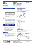
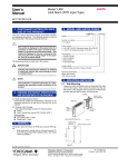
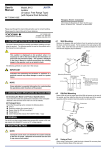
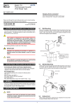
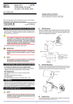
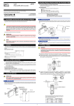
User’s
Manual
IM 77J01H07-01E
Model VJH7
Isolator (Multi-function)
(Isolated Single-output and
Isolated Dual-output Types)
1. CAUTIONARY NOTES FOR SAFE
USE OF THE PRODUCT
For the correct use of this product, read through this manual before
use. The following safety symbol is indicated on the product to ensure safe use.
4. MOUNTING METHODS
4.1
Wall Mounting
Loosen the main unit-fixing screw of the isolator to disconnect the
main unit from the socket. Next, anchor the socket onto the wall
with screws. Then, plug the main unit into the socket and secure
the main unit with the main unit-fixing screw.
CAUTION
Socket
If this symbol is indicated on the product, the operator
should refer to the explanation given in the instruction
manual in order to avoid personnel injury or death to either
themselves or other personnel, and/or damage to the instrument. The manual describes the special care the operator
should exercise to avoid shock or other dangers that may result in injury or loss of life.
Threaded hole for
fixing the main unit
Main unit
Main
unit-fixing
screw
Mounting
screws
The following symbol marks are used only in this manual.
IMPORTANT
Indicates that operating the hardware or software in a particular manner may damage it or result in a system failure.
<Mounting Dimensions>
Unit: mm
29.5 or more
22±0.2
2-M4 or 2-ø4.5 or more
NOTE
2. CHECKING PRODUCT SPECIFICATIONS AND THE CONTENTS
OF PACKING
(1) Model Number and Specification Check
Check that the model number and specifications shown on the
nameplate attached on the side of the product are as ordered.
(2) Contents of the Packing
Check that the packing contains the following items:
● VJH7 main unit, 1
● Instruction Manual (IM 77J1H07-01E), 1
59±0.3
Draws attention to information that is essential for understanding the operations and/or features of the product.
Fig. 4.1
4.2
DIN Rail Mounting
Locate the isolator so that the DIN rail fits into the upper part of
the DIN-rail groove at the rear of the socket, and fasten the socket
using the slide lock at the lower part of the socket.
DIN rail
Accessories:
● Tag number label, 1
● Renge label, 1
● Shunt registor (for specification of current input), 1
W
VIE
A
VIEW A (Rear of socket)
3. GENERAL
This plug-in isolator, which belongs to the JUXTA series of signal
conditioners, receives DC current or voltage signals and converts
them to pairs of isolated DC voltage or current signals.
• Output-2 signal is selectable from a DC voltage signal, DC
current signal, communication function (RS-485), and alarm
output (two relay contacts).
DIN rail
Slide lock
Fig. 4.2
Keep this manual in a safe place.
Network Solutions Business Divisiion
2-9-32, Naka-cho Musashino-shi, Tokyo 180-8750 Japan
Phone: +81-422-52-7179 Facsimile: +81-422-52-6793
IM 77J01H07-01E
1st Edition Nov. 1999
2nd Edition June 2004
2
4.3
Mounting Using a Multi-mounting Base
•
For mounting using a multi-mounting base, see the Instruction
Manual for VJCE (VJ Mounting Base).
4.4
Using Ducts
Wiring ducts should be installed at least 30 mm away from the top
or bottom of the main unit.
4.5
In case of top-and-bottom close mounting
•
For mounting, use M3 screws and crimp-on terminals with insulating sleeves appropriate for the wires used.
Tool of the crimp-on terminals to be used should be appropriate for the crimp-on terminals.
Mount a breaker on the external place.
Mount a switch or 5A circuit breaker on the place near by the
instrument, within operator’s reach. And attach the indication
that it is for disconnecting the instrument.
Transmitter should be mounted horizontally with its top and bottom slits being vertical. The top and bottom slits should not be
covered.
The area for wiring is required above and below the transmitter
(the area with slant lines).
Input signal
Analog input
+
R
40 or more
-
ALM1
ALM1
ALM2
ALM2
ALM2
(72)
ALM1
Shunt resistor
(Externally connected
for current input)
Output-2 signal
78 or more
150 or more
6
2
1
5
4
(29.5)
Analog output Alarm output
2
5
+
2
-
5
29.5 or more
6
9
ALM1
ALM1
ALM2
ALM2
ALM2
8
ALM1
COM
ALM2
RS-485
communication
2 B+
5
A-
6 COM
7
Output-1 signal
(72)
ALM1
11 10
Analog output
40 or more
7
9
Fig. 4.3
+
-
Power supply
L+
5. INSTALLATION LOCATION
•
3
R: 100 Ω
Externally
connected for
current input
3
•
1
For installation, avoid any location where the product may be
subject to vibrations, corrosive gases, or large amounts of
dust, or where the product is exposed to water, oil, solvents,
direct sunlight, radioactive rays, or strong electric or magnetic
fields.
If there is a possibility that lightning could induce a high surge
voltage on the power and signal lines, provide lightning arresters on the line between the field instrument and indoor instrument in order to protect the product. Install a dedicated arrester on the field side and another on the indoor side.
6. EXTERNAL WIRING
WARNING
Turn OFF the power supply and make sure that none of the
cables are not in the hot-line state before carrying out the
wiring to avoid the possibility of electric shock.
Wires are connected to the terminals of the isolator’s socket. M3
screw terminals are provided for the connection of external signals.
Attach a crimp-on lug to each wire for connection to the terminals.
• Recommended cables: A nominal cross-sectional area of 0.5
mm 2 or thicker for signal cables, and that of 1.25 mm 2 or
thicker for power cables, and shielded twisted-pair cables
(AWG24) for communication wiring cables.
All Rights Reserved. Copyright © 1999, Yokogawa M&C Corporation
N-
GND
10
11
8
Fig. 6.1
NOTE
● Keep all sources of noise away from the power and signal cables. Otherwise, accuracy cannot be assured.
● Provide grounding to a grounding resistance of 100 ⍀.
The length of the grounding cable should be 20 m or
less. Directly connect the lead from the ground terminal
(terminal no. 8) of the isolator to the ground. Do not
carry out daisy-chained inter-ground terminal wiring.
●
Direct Current
● “Overvoltage category (Installation category)” describes
a number which defines a transient overvoltage condition. It implies the regulation for impulse withstand voltage. “II” applies to electrical equipment which is supplied from the fixed installation like distribution board.
● “Pollution degree” describes the degree to which a solid,
liquid, or gas which deteriorates dielectric strength or
surface resistivity is adhering. “2” applies to normal indoor atmosphere. Normally, only non-conductive pollution occurs. Occasionally, however, temporary conductivity caused by condensation must be expected.
● Rated fuse of 125VDC, 1A is stored. However, operators can not replace the fuse.
IM 77J01H07-01E
3rd Edition Mar.31,1997-00
3
8. SETTING PARAMETERS
IMPORTANT
● If this instrument is used in a manner not sepecified in
this manual, the protection provided by this instrument
may be impaired.
● If the product is operated by a power supply exceeding
the specifications, the product may become extremely
hot and, as a result, damaged. To prevent this, ensure
the following before turning on the power.
(a) The voltage of the supplied power and the input
signal level meet the specifications of the product.
(b) External wires are connected to the correct terminals (refer to Chapter 5).
● Do not operate the product in the presence of flammable
or explosive gases or vapors. To do so is highly dangerous.
● The product is sensitive to static electricity; exercise
care in operating it. Before you operate the product,
touch a nearby metal part to discharge static electricity.
7. DESCRIPTION OF FRONT PANEL
AND CONNECTION OF HANDY
TERMINAL
7.1
Set the parameters using the Handy Terminal. Refer to the list of parameters in this manual and the Instruction Manual for Handy Terminal (IM JF81-02E).
8.1
8.1.1
8.1.2
NOTE
The conditions for the input hard range (HIGH, MIDDLE,
and LOW) are specified for operations within the range of
accuracy rating. The input range may be set to a range not
meeting these conditions, but take note of accuracy limitations. Similar accuracy limitations exist even when AUTO
is selected. For more information on accuracy limitations,
see the general specifications of VJH7 (GS 77J1H07-01E).
Connecting the Handy Terminal
Communications connector
(for connecting the
Handy Terminal)
8.1.3
Input Range
Set the 0% value of input range to D22: INPUT1 L_RANGE and
the 100% value of input range to D23: INPUT1 H_RANGE within
the numerically specified range.
8.1.4
Alarm-1 LED
(lights up if an alarm occurs)
Input Hard Range
Set by selecting the input hard range from among AUTO, HIGH,
MIDDLE, and LOW in D17: SELECT RANGE. Generally, select
AUTO.
● AUTO: Sets the input hard range automatically with respect to
the input range to be set.
● HIGH: For a span of 5 V or more in an input range of -10 to
+10 V
● MIDDLE: For a span of 2.5 V or more in an input range of -5
to +5 V
● LOW: For a span of 0.5 V or more in an input range of -1 to
+1 V
Front Panel
Connect the modular jack-to-connector adapter to the connection
cable (with 5-pin connector) of the Handy Terminal and then connect this adapter to the communications connector of the distributor.
Input Type
Set by selecting input type from among VOLTS (DC voltage) and
CURRENT (DC current) in D16: INP TYPE.
The communications connector in the front panel is used for setting up parameters through the Handy Terminal. The alarm-1 and
alarm-2 LEDs light up if an alarm occurs (those LEDs are provided only when the output-2 is specified for alarm output).
7.2
Settings Related to Inputs and Outputs
Direction of Output Action
Analog output signals can be reversed. To reverse the signal from
output-1, set D38: OUT1 DR to REVERSE. For output-2, set D39
OUT2 DR to REVERSE. To return the output-1 signal to normal,
set D38: OUT1 DR to DIRECT. For output-2, set D39: OUT2 DR
to DIRECT.
ALM1
ALM2
Alarm-2 LED
(lights up if an alarm occurs)
8.2
* The LEDs are provided only when output-2
is specified for alarm output.
Fig. 7.1 Front Panel
Communications
connector
F9182EE
Connection cable (optional)
Settings Related to Communication
Function
Set the following parameters when output-2 is specified for communication function. For more information on the communication
function, see the Instruction Manual for VJ Series Communication
Function (IM 77J1J11-01E).
8.2.1
Communication Protocol
Set the communication protocol by selecting from among PCLINK, PC-LINK WITH SUM, MODBUS ASCII, MODBUS
RTU, and LADDER in F01: PROTOCOL.
8.2.2
VJ Series
E9786WH
Modular jack-to-connector
adapter (optional)
JHT200
Handy Terminal (optional)
Fig. 7.2 Connecting the Handy Terminal
Communication Address
Set the address number of the isolator numerically in a range of 1
to 99 in F02: ADDRESS.
8.2.3
Baud Rate
Set the baud rate by selecting from among 1200, 2400, 4800, and
9600 bps in F03: BAUD RATE.
8.2.4
Parity
Select and set NONE, EVEN, or ODD in F04: PARITY.
8.2.5
Data Length
Select and set 7 bits or 8 bits in F05: DATA LEN.
All Rights Reserved. Copyright © 1999, Yokogawa M&C Corporation
IM 77J01H07-01E
3rd Edition Mar.31,1997-00
4
Set the following parameters when output-2 is specified for alarm
output.
When HIGH ALM (high-limit alarm) is set: Alarm is released
when input signal < (alarm setpoint - hysteresis).
* When LOW ALM (low-limit alarm) is set: Alarm is released
when input signal > (alarm setpoint + hysteresis).
● Setting range: A range of 0 to 100% of input range
● Setting resolution: 0.1%
8.3.1
8.3.4
8.2.6
*
Stop Bit
Select and set 1 bit or 2 bits in F06: STOP BIT.
8.3
Settings Related to Alarm Output
Alarm Setpoints
8.3.2
Direction of Alarm Action
Select the direction of alarm-1 action and that of alarm-2 action from
among HIGH ALM (high-limit alarm) and LOW ALM (low-limit
alarm) and set each in E05: ALM1 ACTION (direction of alarm-1
action) or E06: ALM2 ACTION (direction of alarm-2 action).
● To activate alarm status when input signal ⱖ alarm setpoint,
select HIGH ALM.
● To activate alarm status when input signal ⱕ alarm setpoint,
select LOW ALM.
8.3.3
Alarm ON Delay and Alarm OFF Delay
Set alarm-1 and alarm-2 ON delays in E11: ON DELAY1 and
E12: ON DELAY2 and then alarm-1 and alarm-2 OFF delays in
E13: OFF DELAY1 and E14: OFF DELAY2.
An alarm ON delay is a delay time from the establishment of alarm
condition to alarm output; an alarm OFF delay is a delay time from
the establishment of return-to-normal condition to output.
● Setting range: 0 to 999 seconds
● Setting resolution: 1 second (Note that about 0.2 second will
be added to set time to prevent erroneous operation.)
For example, when an alarm ON delay is set to 1 second, alarm
output is generated if alarm status continues for more than 1 second after the input value exceeds the alarm setpoint. Further, when
an alarm OFF delay is set to 2 seconds, alarm output is released if
normal condition continues for more than 2 seconds after the input
value has returned to normal from the alarm status.
Set the alarm setpoints of alarm-1 and alarm-2 in E03: SET
POINT1 and E04: SET POINT2 numerically.
● Setting range: A range of 0 to 100% of input range
● Setting resolution: 0.1%
Hysteresis
8.3.5
Set alarm-1 and alarm-2 hysteresis, in E09: HYSTERESIS1 and
E10: HYSTERESIS2. Hysteresis is a value added to the alarm
setpoint in order for an alarm status to be released (to normal) after
the alarm status has been activated. The alarm status will be released in the following conditions, depending on the direction of
alarm action.
Direction of Relay Action
Set the direction of relay energizing in alarm-1 normal condition
and alarm-2 normal condition by selecting from among NRM DEENERGIZED (de-energized under normal condition) and NRM
ENERGIZED (energized under normal condition) in E15: RL1
ACTION and E16: RL2 ACTION and set them.
9. DESCRIPTION OF ALARM ACTIONS
This chapter describes examples of alarm actions under the following conditions.
Item
Direction of alarm action
Alarm setting
Hysteresis
Alarm ON delay
Alarm OFF delay
Description of alarm
actions
High-limit alarm OFF
[2]
Normal conditions established
High-limit alarm ON
Normal conditions established
[1]
Alarm-2
Parameter
Setpoint
E06:ALM2 ACTION
Low-limit alarm
E02:SET POINT2
15%
E08:HYSTERESIS2
5%
E12:OFF DELAY2
3 sec.
E14:OFF DELAY2
4 sec.
The alarm sounds if the condition where the input
value is 15% or less of low-limit alarm continues
for more than 3 seconds. After the alarm sounds,
when the condition where input value is more than
20% of the low-limit alarm continues for more than
4 seconds, the status returns to normal.
Alarm conditions established
Alarm conditions established
[%]
100
Alarm-1
Parameter
Setpoint
E05:ALM1 ACTION
High-limit alarm
E01:SET POINT1
80%
E07:HYSTERESIS1
10%
E11:ON DELAY1
1 sec.
E13:OFF DELAY1
2 sec.
The alarm sounds if the condition where the input
value is 80% or more of high-limit alarm continues
for more than 1 second. After the alarm sounds,
when the condition where input value is less than
70% of the high-limit alarm continues for more than
2 seconds, the status returns to normal.
[1]: Alarm status does not continue for more than 1 second after the
alarm conditions are established at alarm-1.
[2]: Normal status does not continue for more than 2 seconds after the
normal conditions are established at alarm-1.
[3]: Alarm status does not continue for more than 3 seconds after the
alarm conditions are established at alarm-2.
[4]: Normal status does not continue for more than 4 seconds after the
normal conditions are established at alarm-2.
Alarm-1 setpoint (80%)
80
Alarm-1 hysteresis (10%)
4 sec.
Alarm-2 hysteresis (5%)
Alarm-2 setpoint (15%)
0
Alarm-1 action
Alarm-2 action
Low-limit alarm OFF
[4]
3 sec.
Alarm-2 OFF delay
Normal conditions
established
Normal conditions
established
Alarm-2 ON delay
[3]
Low-limit alarm ON
Alarm conditions
established
Alarm-1 OFF delay
20
15
2 sec.
Alarm-1 ON delay
40
1 sec.
Alarm conditions
established
60
Elapsed time
Normal
1 sec.
Normal
Alarm
Normal
All Rights Reserved. Copyright © 1999, Yokogawa M&C Corporation
Alarm
Normal
IM 77J01H07-01E
5
10.LIST OF PARAMETERS
No.
Item
01 Model
02 Tag no.
03 Self-check result
Display
MODEL
TAG NO
SELF CHK
A
A01
A05
A06
A07
A08
A17
A18
A20
A60
DISPLAY1
INPUT1
OUTPUT1
OUTPUT2
ALM1 STATUS
ALM2 STATUS
STATUS
REV NO
MENU REV
SELF CHK
Display 1
Input value
Output value 1
Output value 2
Alarm-1 status
Alarm-2 status
Status
Rev. no.
Menu rev.
Self-check result
Remarks No.
Item
Display
Display items
B Display 2
B01 Input value 1
B05 Output value 1
B06 Output value 2
B60 Self-check result
*1
DISPLAY2
INPUT1
OUTPUT1
OUTPUT2
SELF CHK
*1 The Status is displayed for service personnel to see history
records.
Setting items
E Setting (alarm output)
E01 Alarm-1 setting
E02 Alarm-2 setting
E03 Alarm-1 setting
E04 Alarm-2 setting
E05 Direction of alarm-1 action
E06 Direction of alarm-2 action
E09 Alarm-1 hysteresis
E10 Alarm-2 hysteresis
E11 Alarm-1 ON delay setting
E12 Alarm-2 ON delay setting
E13 Alarm-1 OFF delay setting
E14 Alarm-2 OFF delay setting
E15 Direction of alarm-1 relay action
E16 Direction of alarm-2 relay action
E60 Self-check result
F Setting (communication)
F01 Communication protocol
There are items not displayed depending on what output-2 is
specified.
F02 Address
F03 Baud rate
F04 Parity
F05 Data length
F06 Stop bit
F60 Self-check result
Adjusting items
Test items
P Adjustment
ADJUST1
Q Test
P02 Zero adjustment of input-1
ZERO ADJ1
Q01 ON/OFF of RJC
P03 Span adjustment of input-1 SPAN ADJ1
Q02 Forced output 1
P12 0% adjustment of output-1
OUT1 0%
Q03 Forced output 2
P13 100% adjustment of output-1 OUT1 100%
Q04 Forced output (alarm 1)
P14 0% adjustment of output-2
OUT2 0%
Q05 Forced output (alarm 2)
P15 100% adjustment of output-2 OUT2 100%
Q60 Self-check result
Adjustment of external input
P17
RESISTOR ADJ
resistance
P60 Self-check result
SELF CHK
D Setting (I/O)
D01 Tag no. 1
D02 Tag no. 2
D03 Comment 1
D04 Comment 2
D16 Input type
D17 Selection of input hard range
D22 Input low range
D23 Input high range
D38 Direction of output-1 action
D39 Direction of output-2 action
D60 Self-check result
SET(I/O)
TAG NO.1
TAG NO.2
COMMENT1
COMMENT2
INP TYPE
SELECT RANGE
INPUT1_L_RANGE
INPUT1_H_RANGE
OUT1 DR
OUT2 DR
SELF CHK
11.MAINTENANCE
The product starts running immediately when the power is turned on;
however, it needs 10 to 15 minutes of warm-up before it meets the
specified performance.
For cleaning the instrument, use a soft and dry cloth.
11.1 Calibration Apparatus
● A voltage and current generator (Yokogawa 7651 or the
equivalent)
● A voltmeter (Yokogawa 7562 or the equivalent)
● A precision resistor of 250 ⍀ ± 0.01%, 1 W (for current output)
11.2 Calibration Procedure
Connect the instruments as shown in Fig. 10.1. First adjust the output-1 signal and then the output-2 signal.
Produce input signals equivalent to 0, 25, 50, 75, and 100% of the
input span from the voltage and current generator to the isolator.
Then, check that the isolator’s output signal shows voltages corresponding to 0, 25, 50, 75, and 100% of the input span within the
rated accuracy range.
If the output signal is out of the rated accuracy range, adjust the
output signal level using the Handy Terminal (JHT200).
All Rights Reserved. Copyright © 1999, Yokogawa M&C Corporation
Remarks
SET(ALM)
SET POINT1
SET POINT2
SET POINT1
SET POINT2
ALM1 ACTION
ALM2 ACTION
HYSTERESIS1
HYSTERESIS2
ON DELAY1
ON DELAY2
OFF DELAY1
OFF DELAY2
RL1 ACTION
RL2 ACTION
SELF CHK
SET(COM)
PROTOCOL
ADDRESS
BAUD RATE
PARITY
DATA LEN
STOP BIT
SELF CHK
TEST
RJC
OUT1 TEST
OUT2 TEST
ALM1 TEST
ALM2 TEST
SELF CHK
Shunt resistor
(Externally connected
for current input)
Input signal
Analog input
+
Voltage and
current
generator
-
R
3
1
3
6
2
1
5
4
R: 100 Ω
Externally connected
for current input
N-
GND
10
Analog output
2
5
+
R - Voltmeter
R: For current output using 250 Ω
precision resistor
Power supply
L+
Output-2 signal
9
8
7
Output-1 signal
Analog output
11 10
11
8
7
9
+
R - Voltmeter
R: For current output using 250 Ω
precision resistor
Fig. 11.1
IM 77J01H07-01E