1
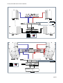
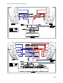
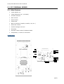
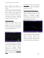
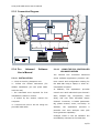
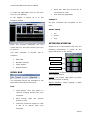
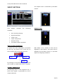
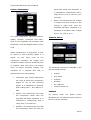
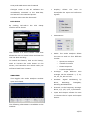
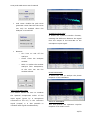
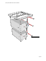
ARRAY/AMS
SERIES USER’S
MANUAL
Array and AMS series User’s Manual
1
INTRODUCTION ................................................................................................................ 4
2
SAFETY............................................................................................................................ 5
3
ARRAY SERIES FEATURES .................................................................................................. 7
4
SYSTEM’S FEATURES......................................................................................................... 8
5
GENERAL SETUP INSTRUCTIONS ........................................................................................ 9
5.1
Passive Box ................................................................................................................................9
5.1.1
Speaker connection ................................................................................................. 9
5.1.2
Amplifier selection ................................................................................................. 10
5.1.3
Array Series and DPA-28X ...................................................................................... 10
5.1.3.1
FEATURES ...................................................................................... 10
5.1.3.2
FRONT PANEL FUNCTIONS ............................................................... 11
5.1.3.3
REAR PANEL FUNCTIONS ................................................................. 11
5.1.4
5.2
Array Series Recommended configurations. .............................................................. 12
PCC ORIGINAL SERIES............................................................................................................... 18
5.2.1
Main Features ....................................................................................................... 18
5.2.2
Pcc Original Series Software User’s Manual ............................................................... 19
5.2.2.1
INSTALLATION ............................................................................... 19
5.2.2.2
Using the PCC Controller Original Series............................................. 19
5.3
PCC ADVANCED SERIES ............................................................................................................. 28
5.3.1
Main Features ....................................................................................................... 28
5.3.2
Back Panel............................................................................................................ 28
5.3.3
Connection Diagram .............................................................................................. 31
5.3.4
Pcc Advaced Software User’s Manual........................................................................ 31
5.3.4.1
INSTALLATION ............................................................................... 31
5.3.4.2
.-USING THE PCC CONTROLLER ADVANCED SERIES ............................ 31
5.4
RIGGING .................................................................................................................................. 40
5.4.1
Safety .................................................................................................................. 40
5.4.2
Single AMS12/AMS15............................................................................................. 41
5.4.2.1
Flown Vertically .............................................................................. 41
5.4.2.2
Mounted On a wall. ......................................................................... 42
5.4.2.3
On wind stand or on SW118 ............................................................. 43
5.4.2.4
Flown Horizontally ........................................................................... 43
5.4.3
Tree or more AMS12 and AMS15 ............................................................................. 44
2/52
Array and AMS series User’s Manual
5.4.3.1
6
Flown Vertically .............................................................................. 44
5.4.4
Array and AMS Flown Horizontally. .......................................................................... 45
5.4.5
Array/AMS series Ground Stack............................................................................... 48
5.4.6
LA312 RIGGING USING HV-312 .............................................................................. 50
Contact ......................................................................................................................... 52
3/52
Array and AMS series User’s Manual
1 INTRODUCTION
Thanks for purchasing TECNARE. This product comprises the best quality designed to offer
a professional use for many years.
Array series represent the highest professional approach to large and medium venues sound
reinforcements, where the best standards are to be achieved. Common characteristics to all
models are:
•
Multiply Birch plywood enclosures.
•
Highest quality speaker standards.
•
Weather proof protection, both in speakers components and enclosures.
•
Very high power capacity.
•
Proprietary wave guide design.
•
Hi-fi quality speaker response.
Active PCC advanced technology versions:
Self-powered systems of high efficiency and low weight.
Systems individually DSP controlled by software in real time.
Graphical Equalizer of 30 bands by acoustic box.
Parametric Equalizer of 10 bands by acoustic box.
Individual control of gain, solo and mute.
Individual Crossover of four bands Linkwitz Riley of 24dB/octave.
Individual Compressor-Limiter by band.
Variable delay on each band of up to 4 ms to adjust acoustic centers.
Communication network able to operate, in real time, with up to 64 boxes
4/52
Array and AMS series User’s Manual
2 SAFETY
Some terminals carry electrical current of
sufficient magnitude to constitute a risk of
electric
shock.
Use
only
commercially-available
high-quality
speaker
cables
2. KEEP THESE INSTRUCTIONS
The
safety
and
operating
instructions
with ¼” TS plugs pre-installed. All other
should be retained for future reference.
installation
3. HEED ALL WARNINGS
or
modification
should
be
performed only by qualified personnel.
This
symbol,
appears,
alerts
presence
of
wherever
you
to
All warnings on the product and in the
it
the
ininsulated
operating instructions should be adhered
to.
4. FOLLOW ALL INSTRUCTIONS
dangerous voltage inside the enclosure –
All
voltage
should be followed.
that
may
be
sufficient
to
constitute a risk of shock.
This
symbol,
operating
and
use
of
instructions
5. DO NOT USE THIS APPARATUS
wherever
it
NEAR WATER
appears, alerts you to important
Do not use the product near water. For
operating
example,
instructions
in
and
the
maintenance
accompanying
literature. Please read the manual
near
a
bathtub,
washbowl,
kitchen sink, or laundry tub, in a wet
basement, or near a swimming pool, and
To reduce the risk of electric
the like.
shock, do not remove the top
6. CLEAN ONLY WITH DRY CLOTH
cover (or the rear section). No
Unplug the unit from the wall outlet before
user
cleaning. Do not use liquid cleaners or
serviceable
parts
inside.
Refer servicing to qualified personnel
aerosol cleaners. Use a damp cloth for
These service instructions are for
cleaning.
use
7. DO NOT BLOCK ANY VENTILATION
by
qualified
service
personnel only. To reduce the
OPENINGS
risk of electric shock do not
Slots and openings in the cabinet back or
perform any servicing other than that
bottom are provided for ventilation, to
contained in the operation instructions.
ensure reliable operation of the limit and
Repairs have to be performed by qualified
to protect it from overheating. These
service personnel.
openings must not be blocked or covered.
1. READ THESE INSTRUCTIONS
The openings should never be blocked by
All the safety and operating instructions
placing the product on a bed, sofa, rug, or
should be read before the product is
similar surface. This product should never
operated.
be placed near or over a radiator or heat
5/52
Array and AMS series User’s Manual
source. This product should not be placed
Do not place this unit on an unstable cart,
in
stand, tripod, bracket, or table. The unit
a
built-in
installation
such
as
a
bookcase or rack unless proper ventilation
may
is
someone, and serious damage to the
provided
or
the
manufacture's
fall,
causing
serious
injury
to
instructions have been adhered to.
appliance. A unit and cart combination
8. DO NOT INSTALL NEAR ANY HEAT
should be moved with care.
SOURCES
13.
This Product should be situated away from
DURING
heat sources such as radiators, stoves, or
WHEN UNUSED FOR LONG PERIODS
other products (including amplifiers) that
OF TIME.
produces heat.
For added protection for this unit during a
9.
DO
NOT
PURPOSE
DEFEAT
OF
THE
THE
SAFETY
POLARIZED
OR
UNPLUG
THIS
LIGHTNING
lightning
storm,
or
APPARATUS
STORMS
when
it
is
OR
left
unattended and unused for long periods of
GROUNDING-TYPE PLUG
time, unplug it from the wall outlet and
A Polarized plug has two blades with one
disconnect the antenna or cable system.
wider than the other. A grounding-type
This will prevent damage to the unit due
plug has two blades and a third grounding
to lightning and power line surges.
prong. The wide blade or the third prongs
14.
are
QUALIFIED
provided
for
your
safety.
If
the
REFER
ALL
SERVICING
SERVICE
TO
PERSONNEL.
provided plug does not fit into your outlet,
SERVICING IS REQUIRED WHEN THE
consult an electrician for replacement of
APPARATUS HAS BEEN DAMAGED IN
the obsolete outlet.
ANYWAY, SUCH AS WHEN THE POWER
10. PROTECT THE POWER CORD FROM
SUPPLY CORD OR PLUG IS DAMAGED,
BEING
LIQUID
WALKED
ON
PARTICULARLY
OR
AT
CONVENIENCE
PINCHED
PLUGS,
RECEPTACLES,
AND
HAS
OBJECTS
HAVE
APPARATUS,
THE POINT WHERE THEY EXIT FROM
BEEN
THE APPARATUS.
MOISTURE,
11.
ONLY
ACCESSORIES
USE
ATTACHMENTS
SPECIFIED
BY
THE
BEEN
SPILLED
FALLEN
THE
OR
INTO
THE
APPARATUS
HAS
EXPOSED
TO
DOES
NOT
RAIN
OR
OPERATE
NORMALLY, OR HAS BEEN FROPPED.
15. WARNING: TO REDUCE THE RISK
MANUFACTURER.
OF FIRE OR ELECTRIC SHOCK, DO
12. USE ONLY WITH CART, STAND,
NOT EXPOSE THIS APPARATUS TO
TRIPOD,
RAIN OR MOISTURE.
BRACKET,
OR
TABLE
SPECIFIED BY THE MANUFACTURER,
16.
OR
EXPOSED
SOLD
WITH
THE
APPARATUS.
APPARATUS
TO
SHALL
NOT
DRIPPING
BE
OR
WHEN A CART IS USED, USE CAUTION
SPLASHING AND NO OBJECTS FILLED
WHEN
WITH LIQUIDS, SHALL BE PLACED ON
MOVING
THE
CART/APPARATUS TO AVOID INJURY
THE APPARATUS.
FROM TIP-OVER.
6/52
Array and AMS series User’s Manual
3 ARRAY SERIES FEATURES
The
Tecnare
integrated
Array
line
Series
of
is
a
fully
provide the best flexibility, which is a very
self-powered
DSP
important
factor
when
multiple
zones
controlle loudspeakers that merge the
within the array are required.
singular advantages o array technology,
Array Series products also incorporate
with the application of computer digital
extra hardware for rigging and stacking as
management
a standard.
audio
benefits
to
professional
reinforcements.
With
this
revolutionary technique the entire concept
of an array box is completely replaced by
the idea that each array element changes
to be an active device, namely a PCC
speaker, controlled with a small laptop via
software. A standard PCC speaker houses
Applications:
•
Live Music
•
Dance Clubs
•
Theatre and corporate events.
•
Houses of workship
•
Touring
one or more module amps and a DSP
processor. All these PCC speakers are
linked
by
a
network
through
a
Main Characteristics:
USB
•
interface to the laptop.
simple, fast and safe rigging.
Once connected, we can control in real
time the parameters of each speaker such
as
volume,
parametric
graphic
•
rigid construction.
parametric
equalisation, crossover, internal delays,
•
Durawound
recall of presets, mute, transfer spectrum
protected
analysis, real time analyzer, spectrum
permanent
applications
are
designed
installation
where
for
and
even
both
•
specially
and
treated
ensure the consistency required to obtain
acoustically
transparent
reticulated foam.
reinforcement professionals solutions to
arrays
coating.
Powder coated perforated steel grid
with
Array Series are engineered to offer sound
controlled
weatherized
One recessed carrying handle.
•
meet almost any challenge.
16mm or 18mm birch plywood.
Durawood
coverage,
required.
DSP
with
finish
Finished in blck semimatt textured
touring
intelligibility, and high SPL levels are
Self-powered
texture
grills.
control, phase check, and more!
Series
Weatherized finish is provided, as
the cabinet is coated with rugged
compressor-limiters, check test, save and
Array
Enclosures made with the latest
techniques ensuring a perfect and
equalisation,
equalisation,
Built in proprietary hardware for
•
Max SPL: Up to 136dB Continuous.
•
Nominal dispersion up to 90ºH x
8ºV
the benefits of line array technology and
7/52
Array and AMS series User’s Manual
4 SYSTEM’S FEATURES
Calculated max SPL: 136dB Continuous
LA 208
Power Handling:
Frequency Response: 78Hz-18kHz ±4dB
Nominal Dispersion: 85ºH x 10ºV @ -6dB
Impedance: 8 Ohm
Net
480W nominal
28.6kg
selfpowered
(width)
x
740
weight:
86
kg
selfpowered
Pcc
Components:
Dimensions(HxWxD): 610x458x262mm
weight:
hetight)x1245
version.
900W continuous
Net
Dimensions(HxWxD): 410 (front H)x310
(depth)mm
Calculated max SPL: 129dB Continuous
Power Handling:
2400W continuous
(rear
Sensitivity: 99dB (1w/1m)
1500W nominal
Pcc
version.
Low:2x12”LF driver band pass horn loaded
Mid: 1x12”HF passed corrected
High: 2x1.5” compression driver attached
Components: 2x8” LF driver, 1x1.4”HF
to a proprietary waveguide device.
exit compression driver
MINIARRAY
LA 122
Frequency Response: 85Hz-18kHz ±4dB
Frequency Response: 69Hz-18kHz ±4dB
Nominal Dispersion: 85ºH x 8ºV @ -6dB
Impedance: 8 Ohm
Impedance: 8 Ohm
Sensitivity: 96dB (1w/1m)
Sensitivity: 100dB (1w/1m)
Calculated max SPL: 128dB Continuous
Power Handling:
Nominal Dispersion: 85ºH x 8ºV @ -6dB
Calculated max SPL: 120dB Continuous
Power Handling:
600W nominal
1100W continuous
Dimensions(HxWxD): 410x600x430mm
Net weight: 40kg selfpowered Pcc version.
Components: 1x12” LF driver, 2x15”HF
250W nominal
480W continuous
Dimensions(HxWxD): 232x543x462mm
Net weight: 27kg selfpowered Pcc version.
Components: 2x6 1/2” LF driver, 1x15”HF
driver on a proprietary waveguide device.
driver on a proprietary waveguide device.
AMS 12
LA 312
Frequency Response: 48Hz-19kHz ±4dB
Frequency Response:
58Hz-19kHz ±4dB
42Hz-19kHz ±4dB (6 elements)
Nominal Dispersion: 90ºH x 8ºV @ -6dB
Impedance: 4 Ohm low, 8 Ohm mid, 8
Ohm high.
Sensitivity: 105dB (1w/1m)
Nominal Dispersion: 90ºH x 30ºV @ -6dB
Impedance: 8 Ohm
Sensitivity: 103dB (1w/1m)
Calculated max SPL: 132dB Continuous
Power Handling:
580W nominal
Dimensions(HxWxD): 705x395x420mm
Net weight: 30kg selfpowered Pcc version.
8/52
Array and AMS series User’s Manual
Components: 1x12” LF driver, 1x1.4”HF
driver on a rotary constant Q horn
5 GENERAL SETUP
INSTRUCTIONS
AMS 15
5.1 Passive Box
Frequency Response: 42Hz-18kHz ±4dB
5.1.1 Speaker connection
Nominal Dispersion: 90ºH x 40ºV @ -6dB
Array series are connected with Speakon
Impedance: 8 Ohm
NL4 plugs except the LA312 unit, which is
Sensitivity: 106dB (1w/1m)
connected with Speakon NL8.
Calculated max SPL: 135dB Continuous
Connectors are wired as follows:
Power Handling:
680W nominal
Dimensions(HxWxD): 890x520x550mm
Net weight: 39kg selfpowered Pcc version.
Components: 1x15” LF driver, 1x1.4”HF
driver on a rotary CD horn
SW118M
Frequency Response: 35Hz-400Hz ±4dB
Speakon
Connector
LA312
LA122
MiniArray
1(+)
1(-)
LF (+)
LF(-)
LF (+)
LF(-)
2(+)
2(-)
MF(+)
MF(-)
HF(+)
HF(-)
3(+)
3(-)
HF(+)
HF(-)
SW118M
SW218M
LF (+)
LF(-)
Impedance: 8 Ohm
Sensitivity: 98dB (1w/1m)
Calculated max SPL: 128dB Continuous
Power Handling:
1000W nominal
2000W continuous
Dimensions(HxWxD): 556x569x691mm
Net weight: 54kg selfpowered Pcc version.
Components: 1x18” LF driver.
The two socket speakon pins in the box
SW218V
are
connected
in
parallel
within
the
Frequency Response: 38Hz-280Hz ±4dB
enclosure, so either connector can be used
Impedance: 4 Ohm
to connect an amplifier or to link to an
Sensitivity: 103dB (1w/1m)
additional Array series or Tenare unit.
Calculated max SPL: 138dB Continuous
Power Handling:
2000W nominal
In an exceptional way, AMS 12 and AMS
4000W continuous
15 can also work in a full range mode by
Dimensions(HxWxD): 1080x580x830mm
shortcutting the 1+ and 2+ pins and 1-
Net weight: 85Kg selfpowered Pcc version.
and 1- pins of the NL4 input speakon
Components: 2x18” LF driver.
connector.
9/52
Array and AMS series User’s Manual
Tecnare recommends a maximum length
compressor, Limiter, USB and Ethernet
cable according to the section cable used.
port connection. Precise frequency control
is achieved with its 1 Hz resolution.
[mm2]
Section
Impedance
1.5
2
3
4
6
8
12
16
2.5
3
4.5
6
9
12
18
24
The DPA - 28X can be controlled or
2.5
5
7.5
10
15
20
30
40
configured in real time on the front panel
8
12
16
24
32
48
64
using the previously stored presets or with
the intuitive PC software via the USB or
Ethernet
interface.
The
Ethernet
port
allows controlling the device from a long
distance using just an Internet connection.
5.1.3.1 FEATURES
5.1.2 Amplifier selection
Tecnare
recommends
amplifiers
in
agreement with the table below:
•
2 Input and 8 Outputs.
•
64 Bits floating point DSP
•
High
performance
24-bit
A/D
Converters
Unit
Conf.
2xSW118M
8xLA312 + 6xSW218M
8xLA122 + 4xSW118
12xLA122 + 8xSW118
12xMiniArray + 4xSW118
1xMA2400
8xMCH4700
4xMCH4700
4xMCH4700
2xMCH4700
•
1 Hz Frequency Resolution
•
Storage
•
output digital loudspeaker management
system designed for the touring or fixed
latest in available technology is utilized
with 64-bit floating point processors and
Analogue
noise and distortion induced by truncation
errors of the commonly used 24-bit fixed-
parameters
A
include
complete
I/O
set
levels,
of
delay,
polarity, 8 bands of parametric EQ per
channel,
multiple
crossover
Unlimited number of presets via
Uploading of 10 collection presets
USB port connection.
•
Ethernet port connection
•
30 bands Input graphic equalizer.
•
8
selections,
bands
Output
Parametric
equalizer per output channel
•
4 ways configurable Crossover
•
Main Delay
•
Input and output Compressor and
Converters. The high-bit DSP prevents
devices.
program
•
sound installation markets. The absolute
point
10
in one step via software
The DPA 28X is a complete 2 input - 8
24-bit
to
software
5.1.3 Array Series and DPA-28X
performance
up
setups
•
high
of
Limiter
•
Configurable Clock
•
Noise Generator
•
Sound Analyzer
•
Phase inverter per band
•
Mute
•
Via adjustable delay
10/52
Array and AMS series User’s Manual
5.1.3.2 FRONT PANEL FUNCTIONS
3
1
2
6
7
5.1.3.3 REAR PANEL FUNCTIONS
8
5
4
9
1
1.-LCD
Screen
CH-A:
Show
all
the
2
3
4
1.- Main Power: Connects via a standard
necessary information to control de unit
IEC socket. A compatible power cord is
supplied with the unit. The voltage input is
1
I BZ A6
P 01
I D:01
3
d efau lt
either 115VAC or 230VAC and is clearly
specified on the unit. Voltage requirement
2
has to be stated upon ordering.
1.- Unit name
2, 3.- XLR input and outputs: Separate 3-
2.-Shows the preset number and
pin XLR connectors are provided for each
identification.
audio input
3.- ID of the Unit.
output
and
stage
output.
employs
The
the
device's
balanced
2.- Rotary thumb wheel CH-A: Controls
impedance topology. All I/O connectors
the presets. To select the desire preset,
have pin 1 as ground (shield), pin 2 as +
press the wheel.
and pin 3 as –
3.- On / SIGNAL / CLIP led CH-A: When
4.- USB connectos: USB connector per
On indicate the unit is On, Signal at the
channel for PC connection.
input and the input level is above the
device’s maximum headroom respectively.
Note: Please refer to section for further
4.-
information.
LCD
Screen
CH-A:
Show
all
the
necessary information to control de unit
5.- Rotary thumb wheel CH-A: Allows you
to switch between presets. To select the
desire preset, press the wheel.
6.- On / SIGNAL / CLIP led CH-A: When
On indicates the unit is On, Signal at the
input and the input level is above the
device’s maximum headroom respectively.
7, 8.- Ethernet connector: Standard RJ-45
female socket.
9.- Power switch: Controls power On/Off.
11/52
Array and AMS series User’s Manual
5.1.4 Array Series Recommended configurations.
12/52
Array and AMS series User’s Manual
13/52
Array and AMS series User’s Manual
14/52
Array and AMS series User’s Manual
15/52
Array and AMS series User’s Manual
16/52
Array and AMS series User’s Manual
17/52
Array and AMS series User’s Manual
5.2 PCC ORIGINAL SERIES
5.2.1 Main Features
•
Input graphic eq.
•
Input parametric eq ( 10 bands).
•
4 band crossover.
•
Gain control.
•
Mute control.
•
Check test.
•
Buit in Analyzer (impulse, transfer, rta, etc..).
•
Real time control.
•
Presets storage in the PC.
•
Grouping.
•
Acoustic center control, between bands.
•
Compressor / Limiter in each band.
Original Series
18/52
Array and AMS series User’s Manual
5.2.2 Pcc Original Series Software
In order to modify the inventory file
according with the user configuration,
User’s Manual
please edit the mentioned file using a text
editor.
5.2.2.1 INSTALLATION
1.- Click on Setup.exe icon
2.-
Follow
the
wizard
EDITING INVENTARY FILE.
instruction
(for
default installation you can press NEXT
Once in the text editor, add and/or erase
until the end)
the serial numbers according with the
* The estimated time required for first
following instructions:
installation is about 1 minute.
* If asked by the wizard, restart the
computer
3.- Connect the unit to the PC using the
provided USB cable.
4.- Copy serfile.ccc and default.inv files
from the installation CD to c: \program
files \PCCcontrol \usbsetup.
NOTE:
DIRECTORY
ROOT
CAN
VARY
DEPENDING ON THE CONFIGURATION OF
THE COMPUTER OF THE USER CASE.
• The serial numbers must always have
5.2.2.2 Using
the
PCC
Controller
Original Series.
four digits.
• No spaces between numbers, not even
STARTING COMMUNICATION.
at the end of the list is required.
Click on the PCC icon
Once
selected
the
inventory
file,
the
software begins, by defect, in the Network
screen:
In the previous window, please select the
inventory file.
19/52
Array and AMS series User’s Manual
The serial numbers of the boxes listed in
MIXER SCREEN.
the inventory file will appear in the left
By pressing F2 key you will open the
column of the screen.
mixer screen where you can find as many
Open the communication port by clicking
faders in yellow colour as boxes connected
to the network.
the next button:
Once opened, it will appear a magnifying
glass icon.
Pressing this icon, the system will start a
communication test. Please check all the
boxes connected to the computer are
responding correctly by checking either
the alternative numbers shown in the back
part of each unit or the front red light
When a box is selected, the fader will turn
from yellow to red.
EDITING CHANEL PARAMETERS.
flashes.
CHANNEL LABEL
BOX TEST
MUTE
GRAPHIC EQUALIZATION
BOX ID
NUMBER ID
GROUP ID
Click
on
“OK.
All
the
devices
are
responding”
CHANNEL FADER
At this point the following window will
appear, where you can find all the boxes
connected to the network by series.
ATENUATION LEVEL
20/52
Array and AMS series User’s Manual
•
Channel label: It allows assigning
a name to each box.
•
Box
It
Fader:
will
attenuate
or
enhancement the level of the box.
Test: When pressing it will emmit
a signal composed by a pink noise to each
GRAPHIC EQUALIZER.
one of the crossover bands of the box.
The purpose of this test, is to verify that
all the components are in good condition.
Mute: It silences the box.
Graphical Equalization: It is acceded to
the graphical equalizer of 30 bands of the
box. (See graphical EQ)
Box ID: It shows the Box ID. This value
can´t be modified by the user.
Number ID: It is a consecutive number
assigned to each box according to the
order of the boxes in the inventory file.
Group ID: With the purpose of being able
to process a set of boxes at the same
time, exists the possibility of grouping the
channels of the mixer.
The graphical equalizer has the following
technical characteristics per box:
- 30 bands of 1/3 of octave from 20Hz to
16kHz
- Enhancement/ Attenuation of +15dB/ 15dB
- Function to keep and to load different
equalizations
- Bypass
The
box
ID
information
shows
the
identification number of the box.
In order to assign a number of group,
right click on group ID, assigning the
MIXER GLOBAL FUNCTION
same number to all boxes that will form
this group. You can switch on and off this
PAGE SELECTOR
PAGE NUMBER
LOAD/SAVELABELS
GROUPS ON/OFF
feature by clicking “Groups Active” in the
right inferior parto of the screen.
Once activated, all the boxes in the same
group will vary their parameters when
GLOBAL MUTE
EDIT MODE
TEST GROUP/GLOBAL
ANALYZER
EXIT
ID NUMBER
varying anyone of the parameters of one
of the boxes of the group.
Have in mind that the system will assign
the same configuration that has the box
located to the vary left of the boxes,
saving this configuration in the memory of
the box.
Page Number:
With PCC
Technology
software it is possible to make the control
of up to 64 boxes. In order to have an
operational control, these 64 boxes are in
four pages of 12 channels each. This
parameter indicates the number of page.
21/52
Array and AMS series User’s Manual
Page
selector:
Changes
the
showed
correspond with the numbers that the
page.
system
Load / Save labels: In order to make
remember that the inventory file can
agile the process of identification of boxes,
contain serial numbers that really do not
it is possible to save the labels of all the
exist in the work network.
channels later to be loaded in another
has
not
detected.
Let
us
Like in the mixer screen the box
session.
that is selected is noticeable with a point
Groups on/off: It switches on/off the
of red colour.
global function group.
Global Mute: It silences all the connected
boxes to the network.
Analyzer: with the activation of this
button,
one
will
enter
the
analyzer
window. AUDIO ANALYZER.
Edit mode: In User mode it is possible to
make modifications in all the parameters
of the box except in cut-off frequency of
the crossover filters, and the delay of each
band. In Service mode the user is allowed
In the left part of the screen are all the
functions that can be used:
to accede to the expert service, an access
It sends a flag test to all the boxes,
key is due to introduce, to select "service"
to verify that communication is being done
and to press "Validate".
properly.
Group / Global Test: it tests that the
communication is working properly.
It saves the data of configuration of
the active box (red) to a file. When
ID Number: It visualizes the number of
identification of the active box ( fader in
red)
making
this
action
is
necessary
to
consider that this configuration is stored
automatically in the box, in such a way
Exit: Exit the software
that when returning to switch on it will do
it with this configuration.
NETWORK SCREEN.
It loads a configuration file to the
At the screen Network, the different boxes
are located in columns according to the
series to which they belong. The serial
numbers
that
appear
Network
are
the
in
the
contained
in
the
that really are connected to the network
those
that
they
remain
box
stores
in
its
memory
this
configuration.
column
inventory file, being in green colour those
and
selected box. As in the previous case the
in
blue
It updates the present configuration
in the internal memory of the box, in such
a way that it is stored in its non-volatile
memory.
22/52
Array and AMS series User’s Manual
NOTE:
THE
EXPLAINED
REMAINING
IN
THE
ICONS
SECTION
HAVE
BEGINNING
BEEN
The graph that appears contains two lines.
THE
The red one corresponds to the activated
COMMUNICATION
band, and the green line corresponds with
the sum of the 10 bands of the equalizer
PARAMETRIC EQUALIZER.
(global equalization).
In order to accede to the parametric
equalizer, select
"Par. EQ " at the
window" Pcc Box Controller ".
It is necessary to consider that each one
of the boxes has it’s own parametric
equalizer, reason why it is necessary to
assure that the box to which is wanted to
apply a parametric equalization is selected
The model and number of the box being
(in red).
equalizer appears in the right superior
part of the window.
In order to equalize, select the desired
band by clicking the band selector. The
central frequency of the band can be
entered in written to modify or also you
can drag with the mouse in the graph the
curve of red colour.
Like with the frequency, the enhancement
or wished attenuation can be written or
can be modified in the graph with the
Technical characteristics:
mouse. In order to select the bandwidth
•
10 parametric Bands.
to work, press with the right button of the
•
Selector of frequency from 20Hz to
mouse in window "Q" and select the
20kHz.
desired Q.
•
Enhancement/Attenuation
of
+15dB/ -15dB by band.
•
Factor of quality, Q: Expressed in
octaves, from 0.1 to 1 octave.
•
Silence (Mute)
•
Activation/
Deactivation
of
equalization (Bypass)
•
Generating of pink noise.
Way of operation:
23/52
Array and AMS series User’s Manual
CROSSOVER.
addition a phase reverse and mute
facilities per band.
•
Adjustable delay by band from 0 to
4ms to fit the acoustic centers of
the different elements from the
box.
As commented in section 2,2 (GLOBAL
FUNCTIONS Of the MIXER) to be able to
modify the parameters of this window it is
necessary
to
enter
mode
service
introducing the user key.
This
window
consists
of
four
filters
crossover, a compressor/ limiter and an
adjustable delay in time or distance by
band.
RESPONSE.
Technical Characteristics:
•
Adjustable
superior
and
inferior
Cut-off frequencies in all the rank
of frequency by band. The slope is
of 24 dB/octave in Linkwitz-Riley
in
the
box
equalization
simultaneous
referring
can
way
be
to
graphical
visualized
with
in
parametric
equalization and crossover.
way.
•
With this screen, all the processing made
Variable Control of adjustable gain
from -24dB to +5dB with the fader
of
the
mouse
in
the
screen
response.
•
Limiter
by
band
with
threshold
control, time of attack and release.
The
threshold
can
be
modified
entering the values manually or
moving the faders at the right of
the window. The limiter has in
24/52
Array and AMS series User’s Manual
By clicking the buttons located in the
SETUP SCREEN.
inferior part of the screen, it is possible to
hide and show the different crossover
bands as well as the different equalization
made.
AUDIO ANALYZER.
The system introduces a powerful audio
analyzer, to which it is acceded by clicking
the analyzing key of the audio mixer. With
this tool, the sound engineer can make
The measurer VU is activated by pressing
the following analyses: impulse response,
the icon VU: It allows simultaneously to
transference function, spectrum analyzer,
visualize the signal of reference and the
phase response and can even obtain the
input signal .
polar plot of the box.
In the right superior part is the generator
of signals, in which it is possible to select
This screen contains several folders in the
the type of signal (sinusoidal, square, pink
superior part with the purpose of being
noise, white noise, etc.), frequency of the
able to visualize all the possible analyses
signal, time of the pulse, interval of the
in separated windows. All these windows
pulse and level of output.
have a common zone of configuration of
analysis located in the inferior part of the
This screen also have adjustment of delay
screen.
of the different bands which can be
obtained with the impulse response.
FFT W INDOW
SIZE
ANALISYS
KIND OF
ANALISYS
W INDOW
AVERAGE
MODE
AVERAGE
SMOOTH
IMPULSE RESPONSE.
START
PRINT
With this screen the answer of the impulse
of
a
certain
room
can
be
obtained.
25/52
Array and AMS series User’s Manual
processing curve made to the box selected
Also
the
existing
delay
between
the
at the network or mixer screen, whereas
different speakers of the box can be
the green line shows the function of
obtained.
transference of the box.
In order to make this process the system
enables markers with the purpose of being
able to visualize in a fast and effective
way
the
existing
delay
between
the
emission of the impulse and the reception
of the same one by an error microphone.
In this way it is possible to
obtain the
retardations relative to each band.
REAL TIME SPECTRUM ANALYZER RTA.
The system allows in addition to make
analysis in frequency with a Real Time
Analyzer.
It
is
possible
in
addition
simultaneously to visualize the spectral
analysis of the signal of reference and the
signal of entrance (microphone).
TRANSFER FUNCTION.
With the use of this screen, the system
calculates the transfer function of the
system, that is to say, the difference
between the signal from the input of the
box to the taking of the acoustic signal by
a measurement microphone.
In the inferior part of screen, are different
functions as adjustment from inferior and
superior
frequency,
capture
curve
snapshot (show peak), erase of captured
curve (reset peak) and show/hide of the
signals reference and input independently.
A very important function that contains
this screen is the possibility of visualizing
and modifying in real time, using the
mouse,
the
(represented
in
graphical
the
figure
equalizer
by
white
triangles) of any of the boxes whose
graphic eq has been selected at the mixer
screen. The yellow line corresponds to the
26/52
Array and AMS series User’s Manual
PHASE RESPONSE.
The screen that is in the superior part
allows to make the measurement of the
phase response of a certain box, the
functions that are in this window are
similar to the ones found in previous
chapters.
POLAR DIAGRAM.
With this function, it is possible to obtain
the polar diagram of the box at different
frequencies.
27/52
Array and AMS series User’s Manual
5.3 PCC ADVANCED SERIES
PCC Advanced series allows control in real time the parameters of each speaker individually
or grouped as we decide, factors such as volume, graphic equalisation, parametric
equalisation, crossover, box delay, clock settings, internal delays, compressor-limiters,
check test, save and recall of presets, mute, transfer spectrum analysis, real time analyzer
spectrum control, phase check…
5.3.1 Main Features
•
Ethernet control.
•
10 built in presets without the use of the software.
•
Unlimited presets storage in the PC.
•
Input graphic eq.
•
Parametric eq on each band ( 4 x 8 bands).
•
General Delay.
•
4 band crossover.
•
Gain control.
•
Mute control.
•
Check test.
•
Buit in Analyzer.
•
Real time control.
•
Presets storage in the PC.
•
Grouping.
•
Acoustic center control, between bands.
•
Compressor / limiter in each output band.
•
Input compressor / limiter.
•
Clock set
5.3.2 Back Panel
Advanced Series:
28/52
Array and AMS series User’s Manual
29/52
Array and AMS series User’s Manual
Cobranet Series:
30/52
Array and AMS series User’s Manual
5.3.3 Connection Diagram
5.3.4 Pcc
Advaced
Software
5.3.4.2 .-USING THE PCC CONTROLLER
ADVANCED SERIES
User’s Manual
The
Tecnare
PCC
Controller
advanced
5.3.4.1 INSTALLATION
series software application provides real-
1.- Click on Pcc12G_Setup.exe icon
time control and configuration editing for
2.-
Follow
the
wizard
instruction
(for
the DPA-28X using a laptop or other PC-
default installation you can press NEXT
compatible computer.
until the end)
In
* The estimated time required for first
control over each individual input channel:
installation is about 1 minute.
Gain,
* If asked by the wizard, restart the
delay, and over each individual output
computer
channel: Crossover, 8 bands parametric
3.- Connect the unit to the PC using the
EQ, phase inverter, mute, and delay. In
provided USB cable.
addition,
addition,
Graphic
the
the
EQ,
application
provides
Compressor,
application
main
provides
a
powerful real time analyzer with pink
noise generator capability.
Changes made in the PC software are
immediately executed in the DPA-28X.
31/52
Array and AMS series User’s Manual
•
To start the application click on the PCC
Icon on your desktop
Save Set: Save the current set of
10 presets to a file.
•
Exit: Exit the application
It will appear a screen as is in the
CONNECT
following image:
On line: Connects the computer to the
unit.
DELAY UNITS
•
ms
•
meter
•
feet
NETWORK WINDOW
Open
the
Connect
dropdown
list
and
select On Line, this will connect your unit
following information is shown at the
to your PC.
The
user
When the PC is connected to the unit, the
interface
is
divided
into
4
upper left corner of the screen.
sections:
Temperature
•
Menu Bar
•
Network window
•
Input section
•
Output section
Limiter
Signal
MENU BAR
Temperature: It shows the temperature of
each output channel.
Limiter: The limiter light show up when
The following menus are available in the
the audio limiter is acting.
Menu Bar at the top of the screen
Signal Indicator: When lighting a input
signal is present.
FILE
•
Load Preset: Click this option to
Load an existing preset from your
computer
•
Save
Preset:
Save
the
current
preset to a file
•
Load Set: Click this option to Load
a Set of 10 preset from your
computer
32/52
Array and AMS series User’s Manual
The output level is controlled by the fader
INPUT SECTION
control.
This
section
contains
the
following
INPUT LEVEL
modules:
•
Unit ID and grouping.
•
Signal Generator
•
Input Level
•
Input Compressor
•
General Setup
•
30 bands Graphic equalizer
UNIT ID AND GROUPING
It shows the units information connected
Main delay in ms, meters or feet can be
to the PC, the active one is the one on
adjusted in this section. The input level is
Red. Double click to activate the unit.
adjusted by the fader control, it provides
signal and clipping indicators.
Unit
Group
Unit ID
By clicking on the group ID box, the user
will be able to assign each unit to a group.
SIGNAL GENERATOR
By selecting active in the dropdown list, a
pink noise signal is generated by the 8
output channels.
33/52
Array and AMS series User’s Manual
signal falls below the threshold. It
INPUT COMPRESSOR
is calibrated in milliseconds, with a
range from 10 ms to 2500 ms (2.5
seconds).
•
Ratio: This determines the change
in output level as a function of the
change in input level, once the
threshold has been exceeded. It is
calibrated in decibels, with a range
from 1.2:1 (off) to 30:1.
The input compressor has four controls:
Attack,
Release,
Threshold
and
GENERAL SETUP
Ratio.
Click on the dropdown list to adjust each
parameter. Click the Bypass button to turn
it off.
About Compression: A compressor is used
to reduce or limit transient peaks in a
signal.
As
the
input
level
to
the
compressor increases, the output level
increases linearly until the threshold point
is reached. After that point, the output
level no longer increases linearly, but
increases
at
a
reduced
rate
that
is
The following controls are available in the
general Setup module:
determined by the ratio setting.
•
•
Presets
Threshold: This control determines
•
RTC Setup
the level at which the compressor
•
Analyzer
begins to act on the incoming
•
Network
signal. It is calibrated in decibels,
•
Pcc LAN Port
with a range from –-40.0 dBu to 17
•
Internet Router IP
dBu.
•
PRESETS
Attack: This determines how fast
the compressor reacts once the
threshold has been exceeded. It is
calibrated in milliseconds, with a
By
pulling
down
the
Select
Preset
dropdown list, 10 different preset saved in
the unit can be selected.
range from 1 ms to90 ms.
•
Release: This determines how fast
the compressor turns off once the
34/52
Array and AMS series User’s Manual
Changes made in the PC software are
•
Display:
Allows
the
user
to
immediately executed in the DPA-28X,
show/hide the input and reference
and stored in the selected preset.
signals.
A Preset name can also be stored.
RTC SETUP
By
clicking
Ctrl+Alt+P
the
RTC
Setup
module will be shown.
This module is a time counter clock that
•
Parameters:
•
Mode: The audio analyzer allows
allows the user to control when and how the
the user to work on four different
unit has been working.
modes:
To Unlock this feature, click on RTC Setup,
send to Tecnare the code shown on the
screen, and introduce the unlock code you
will have back from Tecnare.
•
o
Spectrum Analyzer
o
Transfer Function
o
Phase Response
o
Impulse Response
Average:
Eight
different
time
average can be selected: 1, 5, 10,
ANALYZER
20, 30, 50, 80 and 120.
This toggles the audio Analyzer window
•
open and closed.
Window:
None,
Signal
Windowing
Hamming,
by
Triangular,
Hanning and Blackman
•
Smooth: Is the frequency average.
None, 1/3, 1/6, 1/12, 1/24 Octave.
•
Input and Output: Allows the user
to choose the PC input and output
device.
The following information is available in this
window:
35/52
Array and AMS series User’s Manual
•
Pink noise: Enable the pink noise
generator. Note that the Pink noise
can only be enabled when the
analyzer is turned Off.
TRANSFER FUNCTION
It shows the systems transfer function,
meaning the difference between the signal
from the output of the DPA-28X to the
microphone input signal.
•
Buttons:
o
On: Turn on and off the
analyzer
o
Close: Close the analyzer
window
o
Fade: It makes the window
analyzer 50% transparent,
so the user can see the
window behind.
PHASE RESPONSE
It allows the user to analyze the phase
response of an installation
SPECTRUM ANALYZER
This feature allows the user to visualize
the spectral components either of the
input
signal
(given
by
a
microphone
connected to the PC) or the reference
signal
(output) it is
also
possible
visualize both signal simultaneously.
to
IMPULSE RESPONSE
This tool provide the spectrum impulse
response of a certain room.
36/52
Array and AMS series User’s Manual
NETWORK
This button toggles the network window
open and closed. (Refer to 2.3 for more
information)
37/52
Array and AMS series User’s Manual
GRAPHIC EQUALIZER
Click the ON button to turn the Graphic EQ
on and off
Click and drag on the slider fader to adjust
the equalization from -15dB to +15dB.
Three different kinds of filters can be
selected:
OUTPUT SECTION
The user can manage the output section
by clicking on Out A-B and Out C-D
buttons.
•
Bessel
•
Butterworth
•
L-R
The order of the filter can be selected by
pulling down the Bypass dropdown list,
Second Order filter (12dB/Octave) and
Fourth
Order
filter
(24dB/Octave)
are
available.
Filter cut-off Frequency ranges from 20 to
20,000Hz in 1Hz steps
This
section
contains
the
following
modules:
PARAMETRIC EQ
Eight bands parametric EQ can be opened
by clicking on the Equalizer Out X button.
•
Crossover
•
Graphic EQ
•
Limiter
•
Level
•
Delay
•
Phase inverter
•
Mute
CROSSOVER
Four different settings can be adjusted by
This section contains two crossover filters
the user per band.
per output.
•
Type: The user can select Hi Pass,
Low Pass or band filter
38/52
Array and AMS series User’s Manual
•
Frequency:
Ranges
from
20
to
LIMITER
20,000Hz in 1Hz steps
•
Bandwidth: Ranges from 0.1 to 2
Octaves
•
Level: Ranges from -25dB to 25dB
•
Threshold:
controls
The
are
THRESHOLD
continuously
adjustable from -40dBu (maximum
limiting) to 17dBu
•
Bypass: Turn the module in bypass
mode.
•
Attack: Ranges from 0.1 to 90ms
•
Release: Ranges from 2x to 32x
The user can also modify the equalization
(Frequency and level) by clicking and
dragging the grey points on the screen,
LEVEL/DELAY
•
Level: The output level can be
the selected band will turn from red to
adjusted from -60dB to 12dB, unit
orange.
gain is at the 0dB position.
To copy the desire equalization to other
•
Delay: Ranges from 0 to 10 ms
output just click on Copy button, go to the
•
Phase inverter.
desire output parametric EQ and click on
•
Mute.
the paste button.
39/52
Array and AMS series User’s Manual
5.4 RIGGING
5.4.1 Safety
Flown Systems
•
Installation and set up must be carried out by qualified personal.
•
Inspect the all the rigging components for damage before assembly. Do not use
damaged parts. Contact your supplier for replacements.
•
Ensure that motor hoists, hoist control systems and ancillary rigging components are
currently certified as safe and that they pass a visual inspection prior to use.
•
Ensure the work area is isolated from public access.
•
Do not leave the system unattended during the installation process.
•
Do not leave any object on top of the system. It may fall when the system is flown
and is likely to cause injury.
•
Secondary safety steels must be installed once the system has been flown to the
operating height.
•
Ensure that the system is secure and prevented from pivoting around the motor
hoist.
•
NEVER use other item than Tecnare accessories.
•
When flying outdoor systems ensure that the system is not exposed to excessive
wind or snow loads and is protected from rainfall.
•
When deploying Tecnare Systems always wear protective headwear, footwear and
eye protection
•
Ensure that all local and National regulations regarding the safety and operation of
flying equipment are understood and adhered to.
Ground Stacking
•
Always employ safe lifting procedures and never attempt to build stacks without
sufficient personnel and equipment.
•
Never allow anyone to climb onto a ground stacked PA system.
•
If the stage surface slopes, ensure that the system is prevented from sliding
forwards due to vibration.
•
For outdoor systems ensure that the system is protected from wind forces which
might cause the ground stack or become unstable.
•
Apply the same attention to all safety matters when de-stacking systems.
40/52
Array and AMS series User’s Manual
Accessories are:
•
•
•
•
•
HV-12/M15
•
HS-12/M15
•
HV-208
•
HS-208
FBV_12/FBV_M15
FBH_12/FBH_M15
CV-12/M15
LP_12/M15
5.4.2 Single AMS12/AMS15
•
L_12/M15
5.4.2.1 Flown Vertically
Items required:
•
1x Flying bar for AMS12 or AMS15
(FBV_12 or FBV_M15)
Procedure:
41/52
Array and AMS series User’s Manual
•
Remove the two up-side screws
from the box.
•
Place the FBV_12 or FBV_M15 and
put the screws back.
5.4.2.2 Mounted On a wall.
Items required:
•
LP_ 12 or LP_M15
•
L_12 or L_M15
Procedure:
•
Remove the two up-side screws
from the box.
•
Place the LP_12 or LP_M15 and put
the screws back.
•
Hold the L_12 or L_M15 to the
wall.
•
Place the unit into the L_12 or
L_M15,
place
the
upper
and
bottom screw.
42/52
Array and AMS series User’s Manual
5.4.2.3 On wind stand or on SW118
Items required:
•
1x Wind stand
5.4.2.4 Flown Horizontally
Items required:
•
1x Flying bar for AMS12 or AMS15
(FBH_12 or FBH_M15)
Procedure:
•
Remove the two up-side screws
from the box.
•
Place the FBH_12 or FBH_M15 and
put the screws back.
43/52
Array and AMS series User’s Manual
5.4.3 Tree or more AMS12 and
AMS15
5.4.3.1 Flown Vertically
Items required:
•
Bumper (CV-12/15)
•
Nx FBV_12/M15
•
4Nx Pin Locks
Procedure:
•
Align the boxes with the desire
angle using the pin locks.
•
Remove the two up-side screws
from each box.
•
Place the FBV_12 or FBV_M15 and
put the screws back
44/52
Array and AMS series User’s Manual
5.4.4 Array
and
AMS
Flown
Horizontally.
The following procedure is valid for the LA
and AMS series.
Items required:
•
HV-12 or HV-M15
•
4Nx Pin Locks (+2 for bumper)
Procedure:
•
Select the box and configuration to
be used.
•
Install 4 link bars to the Bumper
using
the
screws
or
pin
locks
included in the package.
•
Connect the first cabinet to the
front link bar and then pull up the
back of the unit until the desired
angle is obtained.
•
Repeat the last step for the rest of
the cabinets.
•
The secondary safety suspension
must
be
independent
of
the
primary suspension and must be
able to carrying the total system
weight
45/52
Array and AMS series User’s Manual
46/52
Array and AMS series User’s Manual
47/52
Array and AMS series User’s Manual
5.4.5 Array/AMS
series
Ground
Stack
Items required:
•
HS-12, HS-M15 HS-312 or HS-208
•
4Nx Pin Locks
Procedure:
Maximum number of cabinets:
IMPORTANT: The number of boxes
and the angle between them must be
in such a way that the total deep
length of the boxes DO NOT EXCEED
the maximum length of the bumper.
•
Select the box and configuration to
be used.
Select the stack position according
•
Install the first cabinet on the
to the speaker used:
bumper using the screws or pin
locks included in the package, the
connection must be placed to the
stack mode.
•
LA122
LA312
Connect the second cabinet to the
front link bar and then adjust the
angle by introducing the back link
AMS12
MiniArray
bar.
•
Repeat the last step for the rest of
the cabinets.
AMS15
LA208
48/52
Array and AMS series User’s Manual
49/52
Array and AMS series User’s Manual
5.4.6 LA312 RIGGING USING HV312
Setup 1
Items required:
•
HV-312 Plataform
•
4Nx Pin Locks (+2 for Bumper)
Procedure:
•
Install the first cabinet on the
bumper using the screws or pin
locks
included
in
the
package.
Elevate the system until the next
cabinet height is reached.
•
Connect the second cabinet to the
front link bar. Adjust the angle by
introducing the back link bar and
remove both Tec-P-312 units.
•
Plug the front link bar.
•
Repeat the last step for the rest of
the cabinets.
50/52
Array and AMS series User’s Manual
Setup 2
Items required:
•
HV-312
•
4Nx Pin Locks (+2 for Bumper)
Procedure:
•
Install the first cabinet on the
bumper using the screws or pin
locks included in the package.
•
Connect the rest of the cabinets to
the front link bar. Adjust the angle
by introducing the back link bar
and remove both Tec-P-312 units.
•
Elevate the system until the next
cabinet reaches the desire angle,
plug the back link bar.
•
Remove the pin lock that holds the
Tec-P-312 unit and remove it.
•
Repeat the last 2 step for the rest
of the cabinets.
51/52
Array and AMS series User’s Manual
6 Contact
Exel Acoustics, S.A.
Poligono Industrial Monte Boyal
C/Encinar, 282
45950 Casarrubios del Monte
Toledo – Spain
[email protected]
Phone: +34 918 170 110
Fax: +34 918 183 053
52/52


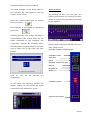
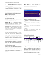
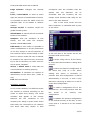

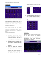
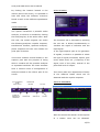


![TECNARE DPA 28X OWNER [Ingles]](http://vs1.manualzilla.com/store/data/005945802_1-b9e6af5d2577bc9a733b6f858960f622-150x150.png)