1
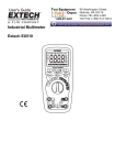
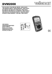
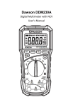
DCM730
Digital Clamp Meter
User’s Manual
Table of Contents
LIMITED WARRANTY AND
LIMITATION OF LIABILITY........................1
Out of the Box..................................................1
Safety Information ...........................................2
INTRODUCTION ......................................4
Components and Buttons..................................6
Names of the Components................................6
Switches and Buttons.......................................9
Display..........................................................10
USING THE METER.................................11
Display Hold...................................................11
Manual Mode..................................................11
MAX/MIN Display............................................11
Switching Between Functions..........................11
Backlight and clamp light .... . ...........................12
Auto Power Off ..............................................12
Measurement Preparation ..............................12
AC Current ....................................................13
Table of Contents
AC/DC Voltage ..............................................13
Frequency and Duty Cycle..............................14
Resistance....................................................16
Diodes..........................................................17
Continuity......................................................17
Capacitance..................................................18
Non-Contact Voltage (NCV)............................18
SPECIFICATIONS..................................19
General Specifications...................................19
Technical Specifications.................................20
MAINTENANCE.....................................24
General Maintenance.....................................24
Battery Replacement ..................................25
Test Leads Replacement ................................25
Contact Dawson....................................25
LIMITED WARRANTY AND
LIMITATION OF LIABILITY
This instrument from Dawson Tools Inc. will be free from
defects in workmanship and material for three years from
the date of original purchase. This warranty does not
cover defects resulting from damage caused by the user
such as drops, neglect, misuse, unauthorized alteration,
usage outside of specified conditions, contamination, or
improper repair/maintenance. To receive service on the
instrument if it becomes necessary during the warranty
period, contact your nearest Dawson authorized service
center at (800) 898-6991 or visit www.DawsonTools.com
to obtain a return authorization (within the US only).
A return authorization is necessary before returning any
instrument to Dawson; no service will be provided without
a return authorization. The user is responsible for
properly packing the unit and charges such as shipping,
freight and insurance charges. The extent of Dawson's
liability is limited solely to the repair/replacement of the
instrument. The above warranty in its entirety is inclusive
and no other warranties, written or oral, are expressed or
implied.
Safety Information
WARNING:
TO REDUCE THE RISK OF FIRE, ELECTRICAL
SHOCK, DAMAGE TO THE INSTRUMENT OR
PERSONAL INJURY, PLEASE FOLLOW THE
SAFETY INSTRUCTIONS DESCRIBED IN THE USER
MANUAL.
WARNING:
TO ENSURE SAFE OPERATION AND LIFE OF THE
METER, DO NOT PLACE THE METER IN ANY
ENVIRONMENT WITH HIGH PRESSURE, HIGH
TEMPERATURE, DUST, EXPLOSIVE GAS OR
VAPOR.
Safety Symbols
Symbol
Conforms to relevant European Union
directives
Out of the Box
Check the meter and accessories thoroughly before
using the meter. Contact your local distributor if the meter
or any components are damaged or malfunction.
Dangerous voltage may be present.
Double Insulation, Protection Class II.
Accessories
• Test leads
• User’s manual
• 1.5V AAA battery
• Case
1pc
1pc
3pc
1pc
01
Definition
Important safety message
C
CONFORMS TO UL STD. 61010-1,
IEC 61010-2-032
CERTIFIED TO CSA STD. C22.2
No. 61010-1 and IEC 61010-2-032
02
This product has been tested to the
requirements of CAN/CSA-C22.2
No. 61010-1, second edition, including
Amendment 1, or a later version of the
same standard incorporating the same
level of testing requirements.
Ground
Warning Symbols
WARNING:
Risk of danger; important safety information. See
User’s manual.
CAUTION:
Statement identifies conditions and actions that a
failure to follow the instructions could result in false
readings, damage the meter or the equipment under
test.
03
Introduction
Overview
DCM730 is a portable, hand-held professional meter that
measures AC/DC voltage, AC current, resistance,
capacitance, diodes, continuity, frequency, duty cycle and
non-contact voltage. This meter is easy to use with one
hand, suitable for professional users or amateurs, and
ideal for school or home use.
Precautions:
Users must follow standard safety instructions while using
the meter:
1. Once the meter is out of the package, check for any
damage to the meter before using.
2. Double check the meter to make sure all the components
are in good condition.
3. Check the test leads before operation. Check the test
leads for damage to the insulation or wires before use.
4. Use the original test leads included in the package for
best performance and safety. If necessary, use
compatible leads with same specifications as the
originals.
5. Make sure to set the meter to the correct functions and
measuring range.
6. Do not use the Meter on a circuit where the measuring
range is over the capable range specified in the User’s
manual.
7. Do not touch the tips of the test leads when performing
measurement.
8. If the measurement is above 60V DC or 30V AC, make
sure to keep fingers behind the barrier and finger guards.
9. Do not use the meter on a circuit if the voltage is above
600V.
04
10. In manual mode, if the value to be measured is
unknown, start the meter in the maximum range and
then adjust accordingly.
11. Remove the leads from the circuit first before switching
between functions.
12. Disconnect power and discharge all capacitors before
measuring resistance, capacitance, continuity or
diodes.
13. Do not measure capacitance before the capacitors are
discharged.
14. Do not operate the meter near explosive gas, vapor or
dust.
15. Stop using the meter if the meter or test leads appear
damaged or do not function properly.
16. Do not use the meter unless the battery case is
securely fastened to the back of the meter.
17. Do not expose the meter to direct sunlight, heat, or
moisture.
05
Components and Buttons
Names of the Components
1.Current clamp
2.NCV indicator
3.Function button
4.Range button
5.Maximum/Minimum button
6.Display
7.Common jack (-)
8.Input jack (+)
9.Frequency/duty cycle button
10.Non-contact voltage button
11.Data hold/backlight button
12.Rotary switch
13.Clamp center
14.NCV sensor
15.Worklight
16.Test lead holder
17.Battery cover
18.Clamp trigger
19.Hook (to hang meter)
20.Test lead holder
06
14
1
13
15
20
12
2
16
19
11
3
18
WARNING
ATTENTION
4
5
10
9
TO AVOID ELECTRICAL
SHOCK, REMOVE TEST
LEADS BEFORE OPENING
BATTERY COVER.
POUR ÉVITER TOUT CHOC
ÉLECTRIQUE, RETIREZ
LES CORDONS DE TEST
AVANT D’OURVIR LA
BATTERIE OU LE
COUVERCLE DU FUSIBLE
600V CAT III
DC1.5Vx4,SIZE AAA
6
C
7
8
07
08
17
Display
Switches and Buttons
FUNC button: to switch between functions.
RANGE button: to switch to manual range.
AUTO
/
button: to hold the reading or to turn on backlight.
MAX-MIN
REL
DC
µnF
%Hz
kMΩ
mVA
MAX/MIN button: to switch between max. and min. display.
AC
Hz% button: to switch between frequency and duty cycle.
NCV button: to activate non-contact voltage detection.
Rotary Switch: switch between measurement modes.
INPUT: Input jack for measuring voltage, resistance,
capacitance, diodes, continuity, frequency,
duty cycle.
COM: Common input jack.
AC, DC
AUTO
MAX
MIN
H
%
mV,V
A
nF, µF
Ω, kΩ, MΩ
Hz, kHz, MHz
09
Alternating current, Direct current
Diode, continuity
Auto-range mode
Maximum measurement
Minimum measurement
Auto power off
Low battery
Display hold
Percentage (duty cycle)
MilliVolt, Volt (voltage)
Amp (current)
Nanofarads, microfarads, millifarads
Ohms, kilohms, megaohms
Hertz, kilohertz, megahertz
10
Using the Meter
Backlight and clamp light
Display Hold
• Hold / to turn on the display backlight; the backlight
will stay on for 30 seconds before it automatically turns off.
• To turn off the backlight manually, hold / again.
• When the meter is in current mode, turning on the
backlight will also activate the worklight, making it easier
to use the clamp in dark areas.
During measurement, press / to hold the current
reading on the display. Press again to release the hold.
Manual Mode
• The default range in voltage and resistance modes is
auto. To switch to manual range, press “RANGE” and
the display switches to manual mode. Each press of the
button increases the range and returns to the lowest
range when pressed in the highest range.
• Hold “RANGE” to switch back to auto-range.
Note:
In current mode, manual is the only mode available.In
frequency and capacitance modes, only auto-range is
available.
MAX/MIN Display
Press “MAX/MIN” to show the maximum value recorded
since the button was pressed. Press “MAX/MIN” again to
show the minimum value recorded since the button was
pressed. Hold “MAX/MIN” to return the display to normal.
Note:
• The meter is set to manual mode when in Max/Min mode.
• The meter cannot display Max/Min measurements when
in frequency/duty cycle, capacitance, diode or continuity
modes.
Switching Between Functions
• When the meter is in voltage mode, press “FUNC” to
switch between DC and AC voltage.
• When the meter is in diode/continuity mode, press
“FUNC” to switch between them.
11
Note:
• The meter uses an LED for a backlight; even though the
backlight is set to turn off after 30 seconds, use only when
necessary to conserve battery life.
Auto Power Off
• If the meter is not used for 15 minutes, the meter will turn
itself off to conserve battery life.
• To turn the meter back on after auto off, press “FUNC”.
• To disable auto power off, hold “FUNC” while turning the
meter on.
Measurement Preparation
• Make sure that when measuring current the current
being measured does not exceed the range selected for
an extended period of time. This can cause overheating
and damage the meter.
• When measuring in manual range and the value to be
measured is unknown, start in the highest range and
adjust the range as needed.
• Make sure to turn the rotary switch to the proper position
before connecting the leads to a circuit.
• When connecting to a circuit, connect the black lead
(COM jack) first before connecting the red lead (INPUT
jack). Remove the leads in the opposite order when
finished.
12
AC Current
WARNING:
TO AVOID ELECTRICAL SHOCK AND INJURY,
PLEASE REMOVE TEST LEADS BEFORE MAKING
CURRENT MEASUREMENTS.
1.Turn the rotary switch to the current position with the
correct range.
2.Press the clamp trigger to open the clamp and insert
the conductor to be measured.
3.Read the measured current value on the display.
Note:
• Measuring two or more conductors will cancel out
readings. Only measure one conductor at a time.
• For best results, keep the conductor in the middle of the
clamp.
• “ ”indicates the maximum input AC Current is 1000 A.
AC/DC Voltage
WARNING:
USE CAUTION WHEN MEASUREING HIGH VOLTAGE
CIRCUITS TO AVOID ELECTRICAL SHOCK AND
INJURY. DO NOT MEASURE INPUT VOLTAGES
HIGHER THEN 600V AC/DC.
1.Insert the black test lead into “COM” jack and red test
lead into “INPUT” jack.
2.Turn the rotary switch to the V The default mode is DC
voltage; press “FUNC” to switch to AC voltage if
necessary; press “FUNC” to switch back to DC voltage.
2.Connect the test leads across the voltage source or load.
3.Read the measured voltage value on the display.
13
Note:
• When measuring small voltage sources, the display will
show unsteady readings until the leads are connected to
the circuit. This is normal due to the high sensitivity of the
meter. The meter will display the correct reading once the
leads are connected to the circuit.
• “ ”indicates the maximum input voltage is 600V DC/AC.
In “mV” range, the maximum input voltage is 600mV
DC/AC.
• In the mV range, the meter will beep if the reading is
greater than 600mV DC/AC.
Frequency and Duty Cycle
In Current Mode (A)
WARNING:
REMOVE THE TEST LEADS FROM THE METER
WHEN PERFORMING A CURRENT MEASUREMENT
WITH THE CLAMP TO AVOID ELECTRICAL SHOCK
AND INJURY.
1.Turn the rotary switch to the current position with the
correct range.
2.Press the clamp trigger to open the clamp and insert the
conductor to be measured.
3.Press “Hz/%” button to measure frequency.
4.Press “Hz/%” again to measure duty cycle if necessary.
5.Read the measured frequency or duty cycle value on
the display.
14
Note:
• Measuring two or more conductors will cancel out
readings. Only measure one conductor at a time.
• “ ”indicates the maximum input current is 1000A AC
RMS.
• Frequency range is 10Hz~1kHz. When the frequency
being measured is less than 10Hz or if the frequency is
higher than 1kHz, the accuracy is not guaranteed.
In Voltage Mode (V)
WARNING:
DO NOT MEASURE VOLTAGES OF MORE THAN
600V AC TO AVOID ELECTRICAL SHOCK AND
INJURY.
1.Insert the black test lead into “COM” jack and red test
lead into “INPUT” jack.
2.Turn the rotary switch to the V position. Press “FUNC”
to switch to AC voltage.
3.Press “Hz/%” button to measure frequency.
4.Press “Hz/%” again to measure duty if necessary.
5.Connect the test leads across the voltage source or load.
6.Read the measured frequency or duty cycle value on
the display.
Note:
• “ ”indicates the maximum input voltage is 600V AC RMS.
• Frequency range is 10Hz~10kHz. When the frequency
being measured is less than 10Hz or if the frequency is
higher than 10kHz, the accuracy is not guaranteed.
15
In Hertz Mode (Hz)
WARNING:
DO NOT MEASURE INPUTS OF MORE THAN 250V AC
TO AVOID ELECTRICAL SHOCK AND INJURY.
1.Insert the black test lead into “COM” jack and red test
lead into “INPUT” jack.
2.Turn the rotary switch to the Hz position.The default
mode is frequency; press “Hz%” to switch to duty cycle
if necessary.
3.Connect the test leads across the voltage source or load.
4.Read the measured frequency or duty cycle value on the
display.
Note:
• Frequency range is 10Hz~10kHz. When the frequency
being measured is less than 10Hz or if the frequency is
higher than 10kHz, the accuracy is not guaranteed.
Resistance
WARNING:
TO AVOID ELECTRICAL SHOCK AND INJURY, TURN
OFF POWER TO THE CIRCUIT AND DISCHARGE ALL
CAPACITORS BEFORE MEASURING RESISTANCE.
1.Insert the black test lead into “COM” jack and red test
lead into “INPUT” jack.
2.Turn the rotary switch to the Ω position.
3.Connect the test leads across the circuit to be tested.
4.Read the measured resistance value on the display.
16
Note:
• If the resistance is too high or the test leads are
disconnected, the display shows “OL”.
• The meter may take several seconds to get a steady
reading if the resistance being measured is more than
1MΩ. This is normal for high resistance circuits.
Diodes
1. Insert the black test lead into “COM” jack and red test
lead into “INPUT” jack.
2. Turn the rotary switch to the
position.The default
mode is diode mode.
3. Connect the red lead to the anode (+) and the black lead
to the cathode (-).
4. Read the measured forward biased voltage drop on the
display.
Note:
• If the leads are connected backwards or to an open
circuit, the display will show “OL”.
Continuity
WARNING:
TO AVOID ELECTRICAL SHOCK AND INJURY, TURN
OFF POWER TO THE CIRCUIT AND DISCHARGE ALL
CAPACITORS BEFORE MEASURING CONTINUITY.
1.Insert the black test lead into “COM” jack and red test
lead into “INPUT” jack.
2.Turn the rotary switch to the
position.Press “FUNC”
to switch to continuity mode.
2.Connect the test leads across the circuit to be tested.
3.Read the measured resistance value on the display.
4.If the resistance is less than 50Ω, the meter’s buzzer
will sound.
17
Note:
If the resistance is higher than 600Ω or the leads are
disconnected, the display shows “OL”.
Capacitance
WARNING:
TO AVOID ELECTRICAL SHOCK AND INJURY, TURN
OFF POWER TO THE CIRCUIT AND DISCHARGE ALL
CAPACITORS BEFORE MEASURING CAPACITANCE.
1.Insert the black test lead into “COM” jack and red test
lead into “INPUT” jack.
2.Turn the rotary switch to the position.
3.Connect the test leads across the circuit to be tested.
4.Read the measured capacitance value on the display.
Note:
• For better accuracy on measurements below 10nF,
touch the tips of the leads together before measurement
and subtract the distributed capacitance of the meter
from the actual measurement.
• For measurements on large capacitances, allow up to
30 seconds for the reading to stabilize.
Non-Contact Voltage (NCV)
1.Hold the “NCV” button.
2.Move the tip of the meter toward the object to be tested.
3.If the voltage detected is greater than 90V AC rms, the
NCV indicator will flash and the buzzer will sound.
Note:
• Even if no indication is given, voltage may still be present.
Do not rely solely on NCV detection to determine the
presence of voltage.
• When measuring AC/DC voltage, the NCV indicator may
flash due to induced voltage.
18
• External power sources/interference may trigger the
NCV indicator.
Technical Specifications
Temperature: 23±5℃.Relative humidity: <75%
Specifications
The meter should be calibrated annually between
18℃ ~ 28℃ and a relative humidity less than 75%.
General Specifications
• Manual and auto range
• Power overload protection
• Maximum voltage between circuit and ground:
600V AC/DC
• Maximum working height: 2000m
• Display: LCD
• Maximum display value: 5999
• Polarity indication” automatically displays ‘-‘
• Overload indication: ‘0L’ Or ‘-0L’
• Sampling frequency: 3 times/sec
• Units displayed: functions with units.
• Auto power off: 15 mins.
• Power : 1.5V AAA batteries
• Low battery indication: display shows“
”
• Operating temperature: 18℃ ~28℃
• Storage temperature:-10℃ ~50℃
• Temperature coefficient: less than 0.1% accuracy/°C
• Size: 244×99×48mm
• Weight: ~410g (Including batteries)
19
AC Current
Range
600A
1000A
Resolution
0.1A
1A
Accuracy
±(2.0% reading+5 digits)
• Maximum input current: 1000A AC
• Frequency Range: 40 ~ 400Hz
DC Voltage
Range
600mV
6V
60V
600V
1000V
Resolution
0.1mV
0.001V
0.01V
0.1V
1V
Accuracy
±(0.7% reading+3 digits)
±(2.0% reading+2 digits)
• Input impedance: 10M Ω
• Maximum input voltage: 600V DC/AC rms
Note:
At small voltage ranges, unsteady readings will appear
before the test leads make contact with the circuit. This is
normal since the meter is highly sensitive. When the test
leads are connected to the circuit, the true reading will be
shown.
20
AC Voltage
Range
6V
60V
600V
750V
Resolution
0.001V
0.01V
0.1V
1V
Accuracy
±(0.8% reading+3 digits)
±(1.0% reading+4 digits)
• Input impedance: 10M Ω
• Maximum input voltage: 600V DC/AC rms
• Frequency Range: 40 ~ 400Hz
Note:
At small voltage ranges, unsteady readings will appear
before the test leads make contact with the circuit. This is
normal since the meter is highly sensitive. When the test
leads are connected to the circuit, the true reading will be
shown.
Frequency
In Current Mode (A)
Range
Resolution Accuracy
99.99Hz
0.01Hz
±(1.5% reading+5 digits)
999.9Hz
0.1Hz
Reference only
>1kHz
0.001kHz
• Measurement range: 10Hz ~ 1kHz.
• Input range: ≥ 60A AC rms (input current will increase
as frequency increases).
• Maximum input current: 1000A AC rms.
21
In Voltage Mode (V)
Range
Resolution Accuracy
99.99Hz
0.01Hz
±(1.5% reading+5 digits)
999.9Hz
0.1Hz
9.999kHz
0.001kHz
Reference only
>10kHz
0.01kHz
• Measurement range: 10Hz ~ 10kHz.
• Input range: ≥ 0.6V AC rms (input voltage will increase
as frequency increases).
• Input impedance: 10MΩ
• Maximum input voltage: 600V AC rms.
In Hertz Mode (Hz)
Range
Resolution Accuracy
9.999Hz
0.001Hz
99.99Hz
0.01Hz
999.9Hz
0.1Hz
±(0.3% reading+5 digits)
9.999kHz
0.001kHz
99.99KHz
0.01kHz
999.9KHz
0.1KHz
9.999MHz
0.001MHz
• Measurement range: 10Hz ~ 10MHz.
• Input range: ≥ 0.2V AC rms (input voltage will increase
as frequency increases).
• Input impedance: 10MΩ
• Maximum input voltage: 250V AC rms.
22
Duty Cycle
Range
0.1 – 99.9%
Capacitance
Resolution
0.1%
Accuracy
± 0.3%
Resistance
Range
Resolution Accuracy
600Ω
0.1Ω
6kΩ
0.001kΩ
±(0.8% reading+3 digits)
60kΩ
0.01kΩ
600kΩ
0.1kΩ
6MΩ
0.001MΩ
±(1.2% reading+3 digits)
60MΩ
0.1MΩ
• Open circuit voltage: 0.4V
• Over-voltage protection: 250V DC/AC rms.
Continuity
Function
Resolution Description
The meter will beep if
measured resistance is
0.1Ω
less than 50Ω.
• Over-voltage protection: 250V DC/AC rms.
Diodes
Function
Resolution
0.001V
Description
Displays forward-biased
voltage drop
• Forward DC current: 1mA
• Reverse DC voltage: 3.3V
• Over-voltage protection: 250V DC/AC rms.
23
Range
40nF
400nF
4µF
40µF
400µF
4000 µ F
Resolution
0.01nF
0.1nF
0.001µF
0.1 µF
0.01 µF
1µF
Accuracy
±(4.0% reading+5 digits)
• Over-voltage protection: 250V DC or AC (RMS)
Maintenance
General Maintenance
• To avoid possible electric shock or personal injury,
repairs or servicing not covered in this manual should be
performed only by qualified personnel.
• Before opening the meter, remove test leads from all
circuits to avoid damage to the meter or personal injury.
• To avoid electrical shock, remove test leads from input
jacks before cleaning.
• To avoid false readings that could lead to possible
electric shock, replace the batteries as soon as the low
battery indicator “ ”appears.
• Clean the instrument case with a damp cloth and mild
detergent. Do not use abrasives or chemical solvents.
• Keep in mind the internal capacitors may retain
dangerous voltages even when the instrument is
turned off.
• Remove the batteries if the meter is not going to be used
for an extended period of time.
24
Battery Replacement
WARNING:
REMOVE THE TEST LEADS FROM THE METER
BEFORE REMOVING THE BATTERY CASE TO AVOID
ELECTRICAL SHOCK AND INJURY.
1. Replace the batteries once the display shows“ ” to
avoid false readings.
2.Remove test leads and unscrew the battery cover and
remove the cover.
3.Replace the used batteries with new ones.
4.Replace the battery cover and tighten the screw.
Note:
Double check the polarity of the batteries before replacing.
Test Leads Replacement
WARNING:
REPLACE THE TEST LEADS WITH IDENTICAL OR
COMPATIBLE LEADS. LEAD SPECS: 1000V 10A.
Replace test leads if leads become damaged or worn.
Contact Dawson
Dawson Tools, Inc.
1142 S. Diamond Bar Blvd., #858
Diamond Bar, CA 91765
Phone: (310) 728-6220
www.DawsonTools.com
25
00-05-0000