1
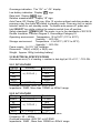
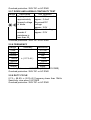
AM-220 & AM-240
DIGITAL
MULTIMETER
OPERATION
1
MANUAL
1. SAFETY INFORMATION
SAFETY SYMBOLS
Warning! Dangerous Voltage (Risk of electric shock).
Caution! Refer to the user’s manual before using this Meter.
Double Insulation (Protection Class II).
Alternating Current (AC).
Direct Current (DC).
Either DC or AC.
Ground (maximum permitted voltage between terminal and ground).
The RESPONSIBLE BODY shall be made aware that, if the instrument
is used in a manner not specified by the manufacturer, the protection
provided by the instrument may be impaired.
The finger or any part of your body shall not be beyond the barrier of
the test probe when measuring.
The following safety information must be observed to insure maximum
personal safety during the operation at this meter.
1.1 Do not operate the meter if the body of meter or the test leads look
broken.
1.2 Check the rotary selector switch to make sure it is at the correct position
before each measurement.
1.3 When making current measurements ensure that the circuit has no
voltage before opening it in order to connect the test leads.
1.4 Do not perform resistance, capacitance, temperature, diode and
continuity test when voltage is present.
1.5 Do not apply voltage between the test terminals and test terminal to
ground that exceed the maximum limit record in this manual.
1.6 Exercise extreme caution when measuring live system with voltage
greater than 60V DC or 30V AC.
1.7 Change the battery when the “ ” symbol appears to avoid incorrect
data.
2. SPECIFICATIONS
2.1 GENERAL SPECIFICATIONS
Display: LCD with a max. reading of 4000.
Range control: Auto range & Manual range control
Polarity: Automatic negative polarity indication.
Zero adjustment: Automatic.
2
Overrange indication: The “OL” or “-OL” display.
Low battery indication: Display " " sign.
Data hold: Display “
” sign.
Relative measurement: Display “!” sign.
Auto Power Off: Display “ ” sign. After 10 minutes without switching modes or
pressing a key the meter will switch to standby mode. Press any key or switch
selector switch to exit standby mode. To disable auto power off, press and
hold SELECT key while rotating the selector switch from off position.
Safety standards:
EMC/LVD. The meter is up to the standards of IEC1010
Double Insulation, Pollution Degree 2, Overvoltage Category III.
Operating environment: Temperature 32 to104°F (0°C to 40°C),
Humidity °‹ 80% RH.
Storage environment: Temperature -4 to140°F (-20°C to 60°C),
Humidity °‹ 90% RH.
Power supply: 2x1.5V “AA” batteries.
Dimension: 156(H) x 86(W) x 38(D) mm
Weight: Approx. 260g (including battery).
2.2 ELECTRICAL SPECIFICATIONS
Accuracies are ±(% of reading + number in last digit) at 23 ± 5°C,°‹75% RH.
2.2.1 DC VOLTAGE
Range
Accuracy
Resolution
400mV
0.1mV
± ( 0.5%+2 )
4V
1mV
40V
10mV
400V
100mV
600V
± ( 0.8%+3 )
1V
Overload protection: 600V DC or AC RMS
Impedance: 10MΩ, More than 100MΩ on 400mV range
2.2.2 AC VOLTAGE
Range
Accuracy
Resolution
400mV
± ( 1.5%+3 )
0.1mV
4V
1mV
± ( 1.0%+2 )
40V
10mV
400V
100mV
600V
± ( 1.5%+3 )
1V
Average sensing, calibrated to RMS of sine wave
Frequency: 40 ~ 400Hz
Overload protection: 600V DC or AC RMS
Impedance: 10MΩ , More than 100MΩ on 400mV range
3
2.2.3 DC CURRENT
Range
Accuracy
Resolution
400µA
0.1µA
± ( 1.2%+3 )
4000µA
1µA
40mA
10µA
400mA
100µA
4A
± ( 2.0%+5 )
1mA
10A
10mA
Overload protection: 0.5A/250V, 10A/250V fuse
2.2.4 AC CURRENT
Range
Accuracy
Resolution
400µA
0.1µA
± ( 1.5%+3 )
4000µA
1µA
40mA
10µA
400mA
100µA
4A
± ( 2.5%+5 )
1mA
10A
10mA
Average sensing, calibrated to RMS of sine wave
Frequency: 40~400Hz
Overload protection: 0.5A/250V, 10A/250V fuse
2.2.5 RESISTANCE
Range
Accuracy
Resolution
400Ω
0.1Ω
4kΩ
1Ω
± ( 1.0%+2 )
40kΩ
10Ω
400kΩ
100Ω
4MΩ
1kΩ
40MΩ
± ( 2.0%+3 )
10kΩ
Overload protection: 250V DC or AC RMS
2.2.6 CAPACITANCE
Range
Accuracy
40nF
± ( 3.0%+10 )
400nF
± ( 2.5%+5 )
4µF
40µF
400µF
± ( 5.0%+10 )
4000µF
± ( 20.0%+20 )
Resolution
10pF
100pF
1nF
10nF
100nF
1µF
4
Overload protection: 250V DC or AC RMS
2.2.7 DIODE AND AUDIBLE CONTINUITY TEST
Range
Description
Test condition
Display read
Forward DC current
approximately
approx. 0.4mA
forward voltage Reversed DC
of diode
voltage
approx. 2.8V
Built-in buzzer
Open circuit voltage
sounds if
approx. 0.5V
resistance is
less than 50_
Overload protection: 250V DC or AC RMS
2.2.8 FREQUENCY
Range
Accuracy
Resolution
10Hz
0.01Hz
100Hz
0.1Hz
1000Hz
1Hz
± ( 0.1%+5 )
10kHz
10Hz
100kHz
100Hz
1000kHz
1kHz
10MHz
10kHz
Sensitivity: sine wave 0.6V RMS (10MHz: 1.5V RMS)
Overload protection: 250V DC or AC RMS
2.2.9 DUTY CYCLE
0.1% ~ 99.9%: ± (2.0%+2) Frequency lower than 10kHz
Sensitivity: sine wave 0.6V RMS
Overload protection: 250V DC or AC RMS
5
2.2.10 TEMPERATURE (AM-240 ONLY)
- Accuracy specification is relative to the user-adjustable temperature offset,
and assumes ambient temperature stable to ± 1°C.
- For ambient temperature changes of ± 5°C, rated accuracy applies after 1
hour.
- Does not include error of the thermocouple probe
Range
-58ºF ~ +1292ºF
-50ºC ~ +700ºC
Accuracy
+/-(1% + 3ºF)
+/-(1% + 2ºC)
Resolution
1° /1°F
Overload protection: 250V DC or AC RMS
3. OPERATION
3.1 DC VOLTAGE MEASUREMENT
1) Connect the black test lead to "COM" socket and red test lead to
the "VΩ mA" socket.
2) Set the selector switch to “V ” position.
3) Measure the voltage by touch the test lead tips to the test circuit where the
value of voltage is needed.
4) Read the result from the LCD panel.
3.2 AC VOLTAGE MEASUREMENT
1) Connect the black test lead to "COM" socket and red test lead to
the "VΩ mA" socket.
2) Set the selector switch to “V ” position.
3) Measure the voltage by touch the test lead tips to the test circuit where the
value of voltage is needed.
4) Read the result from the LCD panel.
3.3 DC AND AC CURRENT MEASUREMENT
1) Connect the black test lead to "COM" socket. For measurement up to
400mA, connect the red test lead to the "VΩmA" socket; for measurement
from 400mA to 10A, connect the red test lead to the "10A" socket
2) Set the selector switch to desired “µA ”, “mA ” or “A ” position.
3) Press “SELECT” key to choose “DC” or “AC” measurement.
4) Remove power from the circuit under test and open the normal circuit path
where the measurement is to be taken. Connect the meter in series with
the circuit.
5) Read the result from the LCD panel.
6
3.4 RESISTANCE MEASUREMENT
1) Connect the black test lead to "COM" socket and red test lead to the
"VΩmA" socket.
2) Set the selector switch to desired “
” position.
3) Connect tip of the test leads to the points where the value of the resistance
is needed.
4) Read the result from the LCD panel.
Note: When measuring resistance values from a circuit, make sure the
power is off and discharge all capacitors.
3.5 CAPACITANCE MEASUREMENT
1) Connect the black test lead to "COM" socket and red test lead to
the "VΩ mA" socket.
2) Set the selector switch to desired “
” position.
3) Press “SELECT” key to choose Capacitance measurement.
4) Connect tip of the test leads to the points where the value of the
capacitance is needed.
5) Read the result from the LCD panel.
Note:
a) Before testing, discharge the capacitor by shorting its leads together. Use
caution in handling capacitors because they may have a charge on them of
considerable power.
b) Before testing, press “REL !” key to eliminate the zero error.
c) When testing 4000µF capacitor, note that there will be approx. 30 seconds
time lag.
3.6 DIODE AND AUDIBLE CONTINUITY TEST
1) Connect the black test lead to "COM" socket and red test lead to
the "VΩ mA" socket.
2) Set the selector switch to desired “
” position.
3) Press “SELECT” key to choose Diode or Audible
Continuity measurement.
4) Connect the test leads across the diode under test, display measures
the approx. forward voltage of this diode.
5) Connect the test leads to two point of circuit, if the resistance is lower than
approx. 50Ω, the buzzer sounds.
Note:
Make sure the power is cut off and all capacitors need to be discharged
under this measurement.
7
3.7 FREQUENCY AND DUTY CYCLE MEASUREMENT
1) Connect the black test lead to "COM" socket and red test lead to the
"VΩmA" socket.
2) Set the selector switch to desired “Hz” position.
3) Press “Hz%” key to choose Frequency or Duty cycle measurement.
4) Connect the probe across the source or load under measurement.
5) Read the result from the LCD panel.
3.8 TEMPERATURE MEASUREMENT
1) Set the selector switch to desired “°F/ °C” position.
2) Press “SELECT” key to choose °F or °C measurement.
3) There is an internal PN Junction Diode Sensor which measures ambient
temperature with no probe connected. This is the 0~40° in the spec.
4) Connect the probe included, or any K-type thermocouple, by inserting the
“+” plug in the "VΩmA" socket & the “-“ in the "COM" socket
5) Put the sensor probe into the temperature field under measurement.
3.9 DATA HOLD AND BACK LIGHT
On any range, press the “
” key to lock display value, and the
“
” sign will appear on the display, press it again to exit.
On any range, press the “
” key for more than 2 seconds to light the
back light, press it again for more than 2 seconds to wink the light.
3.10 MAX/MIN HOLD
Press the “MAX/MIN” key to lock MAX or MIN value, and the “MAX” or “MIN”
sign will appear on the display, press it for more than 2 seconds to exit.
3.11 RELATIVE MEASUREMENT
Press the “REL !” key, you can measure the relative value and “!” sign will
appear on the display, the auto range mode be changed to manual range
mode. Press it again to exit relative measurement and “!” sign disappears,
but you cannot go back to auto range mode. This function is non effective on
Hz% measurement.
3.12 AUTO/MANUAL RANGE
The auto range mode is a convenient function, but it might be faster to
manually set the range when you measure values that you know to be within
a certain range. To select manual range, repeatedly press “RANGE” key until
the display shows the desired range. The range steps upward as you press
“RANGE” key. The meter will go back to auto range mode when you press
“RANGE” key for more than 2 seconds. It can not select manual range mode
on Hz%, capacitance and temperature range.
Caution: while using the manual range mode, if “OL” sign appears on the
display, immediately set range to a higher.
8
4. BATTERY REPLACEMENT
1) When the battery voltage drops below proper operating range, the “
”
symbol will appear on the LCD and the batteries needs to be changed.
2) Before changing the batteries, set the selector switch to “OFF” position.
Remove the two screws on the bottom case and lift the bottom case.
3) Replace the old batteries with the same type battery.
4) Close the bottom case and fasten the screw.
5. FUSE REPLACEMENT
1) This meter is provided with a 0.5A/250V fuse to protect the current
measuring circuits that measure up to 400mA, with a 10A/250V
fuse to protect the 10A range.
2) Ensure the instrument is not connected to any external circuit, set
the selector switch to “OFF” position and remove the test leads from the
terminals.
3) Remove the two screws on the bottom case and lift the bottom case.
Replace the old fuse with the same type and rating: 5x20mm 0.5A/250V
or 6x32mm 10A/250V fuse.
4) Close the bottom case and fasten the screws.
6. MAINTENANCE
1) Before opening the bottom case, disconnect both test leads and never use
the meter before the bottom case is closed.
2) To avoid contamination or static damage, do not touch the circuit board
without proper static protection.
3) If the meter is not going to be used for a long time, take out the batteries
and do not store the meter in high temperature or high humidity
environment.
4) Repairs or servicing not covered in this manual should only by qualified
personnel.
5) Periodically wipe the case with a dry cloth and detergent. Do not use
abrasives or solvents on the meter.
LIMITED WARRANTY
Congratulations! Your new instrument has been quality crafted according to
quality standards and contains quality components and workmanship. It has
been inspected for proper operation of all of its functions and tested by qualified
factory technicians according to the long-established standards of our company.
Your instrument has a limited warranty against defective materials and/or
workmanship for one year from the date of purchase provided that, in the opinion
of the factory, the instrument has not been tampered with or taken apart. Should
9
your instrument fail due to defective materials, and/or workmanship during this
one year period, a no charge repair or replacement will be made to the original
purchaser. Please have your dated bill of sale, which must identify the instrument
model number and serial number and call the number listed below:
Repair Department
ATP – Amprobe
Phone: 954-499-5400
Toll Free: 800-327-5060
Fax: 866-287-7222
Website: www.Amprobe.com
Please obtain an RMA number before returning product for repair. Outside the
U.S.A. the local representative will assist you. Above limited warranty covers
repair and replacement of instrument only and no other obligation is stated or
implied.
www.Amprobe.com
10