1
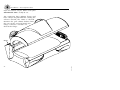
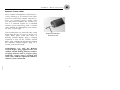
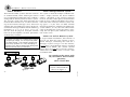
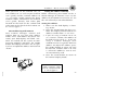
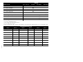
26791-01A
STANDARD 48 MONTH WARRANTY
Your ETS Distributor (including ETS, Inc. if purchased directly), through a manufacturer’s warranty, warrants
your tanning unit to be free of structural defects in material and workmanship, under normal use, for its lifetime.
Your ETS Distributor will, at its discretion, repair any structural defect which materially affects the performance
of the tanning unit, or replace the tanning unit.
For forty-eight (48) months following the shipping date of your tanning unit, your ETS Distributor will provide
replacements for parts that prove to be defective in material or workmanship. Fluorescent lamps, and lamp starters
are warranted against manufacturer’s defects for a period of ninety (90) days following the shipping date of your
tanning unit. Acrylics will be warranted against manufacturer’s defects for a period of 1 year (prorated).
Labor costs associated with repair or replacement work covered by this warranty will be reimbursed for repair or
replacement work required to be performed for a period of one (1) year following the shipping date of your tanning unit. Normal wear and tear, damage from misuse or abuse, damage incurred in transit or damages resulting
from unauthorized repairs or modifications are not covered by this warranty. Warranty coverage does not include
cosmetic abnormalities such as scratches, nicks, dents, or other cosmetic changes that do not materially interfere
with the function of the tanning unit.
THIS STANDARD 48 MONTH WARRANTY IS EXPRESSLY MADE IN LIEU OF ANY OTHER WARRANTIES,
EXPRESS OR IMPLIED, INCLUDING ANY IMPLIED WARRANTIES OF MERCHANTABILITY AND FITNESS
FOR A PARTICULAR PURPOSE, WHICH ARE HEREBY DISCLAIMED. No one has the authority to change or
modify this Standard 48 Month Warranty in any respect. To obtain service under this Standard 48 Month
Warranty, contact your authorized ETS Distributor (or ETS, Inc. if purchased directly). Proof of purchase, including serial number, is required.
IN NO EVENT SHALL YOUR DISTRIBUTOR OR THE MANUFACTURER BE LIABLE AT LAW OR IN EQUITY FOR ANY LOSS, LIABILITY, DAMAGE OR EXPENSE IN AN AMOUNT IN EXCESS OF THE PURCHASE
PRICE RECEIVED, OR FOR LOSS OF USE OR PROFITS, LOSS OF TIME, INCONVENIENCE, RENTAL OR
SUBSTITUTE PRODUCTS, LOSS OF BUSINESS, LOSS OF INCOME, OR ANY OTHER INCIDENTAL, INDIRECT, SPECIAL OR CONSEQUENTIAL DAMAGES. Some states do not allow the exclusion or limitation of
incidental or consequential damages, and the above limitation or exclusion will not apply to residents of some
states. This Standard 48 Month Warranty gives you specific, legal rights and you may have other rights which may
vary from state to state.
All warranty service must be performed by an authorized service person. All labor charges must be authorized by
your ETS Distributor prior to the start of repairs and must not exceed the established rates and time allotment
policies established by your ETS Distributor. If your tanning unit must be returned for service, all freight charges
shall be at your expense. Contact your ETS Distributor for the authorized Service Center nearest you. This warranty is serial number specific and only applies to tanning units purchased through an authorized ETS Distributor.
This warranty is extended to the individual or legal entity whose name appears on the original sales document and
may not be transferred to any other individual or legal entity. This warranty is void if the tanning unit is modified
in any manner from its original design.
To obtain warranty service, contact your place of purchase. Proof of purchase, including serial number, is required for verification. Contact ETS, Inc. only if you purchased your equipment directly.
ETS, Inc. 7445 Company Drive, Indianapolis, IN 46237-9296
1-800-449-3605 In Canada call 1-800-661-6292 or 519-421-1212
26791-01A
i
elcome
Congratulations on your purchase of this technologically advanced sun tanning unit. It has been
designed to provide years of dependable service for you.
Please read all the instructions in this booklet before installing and using the unit. Always be sure to
observe all safety precautions.
ontents
Safety Information . . . . . . . . . . . . . . . . . . . . . . . . . . . . . . . . . . . . . . . .iii
Installation . . . . . . . . . . . . . . . . . . . . . . . . . . . . . . . . . . . . . . . . . . . . . .1
Pre-Installation Planning . . . . . . . . . . . . . . . . . . . . . . . . . . . . . . .1
Unpacking and Inspection . . . . . . . . . . . . . . . . . . . . . . . . . . . . . .2
Hardware Inventory . . . . . . . . . . . . . . . . . . . . . . . . . . . . . . . . . . .3
Tools Required . . . . . . . . . . . . . . . . . . . . . . . . . . . . . . . . . . . . . .3
Assembly Procedures . . . . . . . . . . . . . . . . . . . . . . . . . . . . . . . . . .5
Remote Connections . . . . . . . . . . . . . . . . . . . . . . . . . . . . . . . . .22
Operation . . . . . . . . . .
Before You Tan . . .
Exposure Times . .
Using Your Sunbed
....
....
....
...
.
.
.
.
.
.
.
.
.
.
.
.
.
.
.
.
.
.
.
.
.
.
.
.
.
.
.
.
.
.
.
.
.
.
.
.
.
.
.
.
.
.
.
.
.
.
.
.
.
.
.
.
.
.
.
.
.
.
.
.
.
.
.
.
.
.
.
.
.
.
.
.
.
.
.
.
.
.
.
.
.
.
.
.
.
.
.
.
.
.
.
.
.
.
.
.
.
.
.
.
.
.
.
.
.
.
.
.
.
.
.
.
.
.
.
.
.
.
.
.
.26
.26
.26
.27
Care and Maintenance . . . . . . . . . . .
Cleaning After Use . . . . . . . . . .
Thorough Periodic Cleaning . . .
Mechanical Inspection . . . . . . .
Lamp and Acrylic Replacement
Under the Bench . . . . . . . . . . .
.
.
.
.
.
.
.
.
.
.
.
.
.
.
.
.
.
.
.
.
.
.
.
.
.
.
.
.
.
.
.
.
.
.
.
.
.
.
.
.
.
.
.
.
.
.
.
.
.
.
.
.
.
.
.
.
.
.
.
.
.
.
.
.
.
.
.
.
.
.
.
.
.
.
.
.
.
.
.
.
.
.
.
.
.
.
.
.
.
.
.
.
.
.
.
.
.
.
.
.
.
.
.
.
.
.
.
.
.
.
.
.
.
.
.
.
.
.
.
.
.
.
.
.
.
.
.
.
.
.
.
.
.
.
.
.
.
.
.
.
.
.
.
.
.29
.29
.29
.29
.30
.34
26791-01A
Troubleshooting . . . . . . . . . . . . . . . . . . . . . . . . . . . . . . . . . . . . . . . . .35
ii
afety Information
LABELING NOTICE: Labels are affixed on all systems to inform the user of possible dangers. Regulations are stated in 21 CFR, Section
1040.20, and require that all products manufactured after September 8, 1986 which use sunlamps must display the following:
DANGER
Ultraviolet radiation. Follow instructions. Avoid overexposure. As with natural sunlight, overexposure can cause
eye and skin injury and allergic reactions. Repeated exposure may cause premature aging of the skin and skin
cancer. WEAR PROTECTIVE EYEWEAR; FAILURE TO MAY RESULT IN SEVERE BURNS OR LONGTERM INJURY TO THE EYES.
Medications or cosmetics may increase your sensitivity to the ultraviolet radiation. Consult physician before using sunlamp if you are
using medications or have a history of skin problems or believe yourself especially sensitive to sunlight. If you do not tan in the sun, you
are unlikely to tan from the use of this product. Children, the elderly, or fair skinned people who always burn easily and either never tan
or tan minimally should not use this equipment.
To use, lie down under canopy and pull down as far as adjustment will allow maintaining at least 3.5 inches (8.9 centimeters) between
your body and canopy clear plastic panel and side tanner clear plastic panel, otherwise overexposure may occur. Minimum use distance
elsewhere is touching the clear plastic panels. Do not use without clear plastic panels in place. Untanned persons should not tan on consecutive days during their first week of tanning. Never tan more than once a day. Tanning normally appears after the first few sessions
and maximizes after approximately four weeks. Tan once or twice per week thereafter to maintain appearance. Persons already having
a base tan may begin at advanced levels corresponding to the extent of their base tan.
RECOMMENDED EXPOSURE TIMES IN MINUTES
Skin Type:
I Sensitive Skin
II Light
III Normal
IV Dark
MAXIMUM EXPOSURE TIME IS 12 MINUTES
Level 1/Week 1
1st-3rd Sessions
(Burns easily and severely and does not tan.)
(Burns easily and severely and tans minimally.)
(Burns moderately and tans average.)
(Burns minimally, tans easily and above average.)
2
3
4
Level 2
Level 3
Level 4
NOT RECOMMENDED FOR TANNING
4
7
10
6
9
12
7
10
12
Subsequent
Maximum
12
12
12
New lamps emit approximately 10% more ultraviolet radiation during the first 50 hours of operation. Recommended tanning times should
therefore be reduced by approximately 10% during that period.
WARNING: • Read the instructions booklet before using this sunlamp product. • All persons in the room should wear protective eyewear
when lamps are on. Recommended eyewear: provided eyeshields or equivalent eyewear as defined under 21 CFR 1040.20. Other types
of eyewear may not provide adequate protection. Failure to use protective eyewear may result in severe burns or other eye injury. If discomfort develops, discontinue use and consult a physician.
ONLY THE FOLLOWING LAMPS HAVE BEEN CERTIFIED FOR USE IN THE SOLARFORCE 648:
Velocity® VS-R™ Wolff® Model VEL71-T12/160W PREHEAT - BIPIN
Heraeus E400 HPT, Philips Model HPA 400/30s or CosmoTech Model 23045 (facial unit)
MARQUIS, Wolff System® Model CF26W (shoulder unit)
DISCONNECT POWER BEFORE ATTEMPTING TO CLEAN, RELAMP, OR ENGAGE IN THE MAINTENANCE OF THIS PRODUCT.
THIS EQUIPMENT MUST BE EARTH GROUNDED.
This product is in conformity with performance standards for sun lamp products under 21 CFR PART 1040.20 and
ANSI/UL Standard 482. Certified to CAN/CSA Standard C22.2 NO. 224.
88465
26791-01A
iii
Renseignements sur la Sécurité
Rayonnement ultraviolet. Veuillez suivre les instructions. Évitez une exposition excessive. Tout comme pour les
rayons du soleil, une exposition excessive peut causer des blessures aux yeux et à la peau et provoquer des réactions allergiques. Une exposition répétée peut causer le vieillissement prématuré de la peau et provoquer le cancer de la peau. PORTEZ
DES LUNETTES PROTECTRICES: LE NON-RESPECT DE CETTE CONSIGNE DE SÉCURITÉ PEUT ENTRAÎNER DE GRAVES
BRÛLURES OU DES LÉSIONS OCULAIRES À LONG TERME. Les médicaments ou les produits cosmétiques peuvent augmenter votre
sensibilité au rayonnement ultraviolet. Consultez un médecin avant d’utiliser la lampe solaire si vous prenez des médicaments, si vous
souffrez d’une maladie cutanée ou si vous croyez être particulièrement sensible aux rayons du soleil. Si vous ne bronzez pas au soleil, il
est peu probable que vous bronzerez sous une lampe solaire. Les enfants, les personnes âgées et les personnes qui ont une peau claire
qui brûle facilement, ne bronze jamais ou alors très peu, ne devraient pas utiliser cette lampe.
Étendez-vous sous la partie supérieure, puis abaissez celle-ci aussi bas que possible, en veillant cependant à conserver un espace d’au
moins 3,5 pouces (8,9 centimètres) entre le corps et le panneau de plastique transparent de la partie supérieure et le panneau de plastique
transparent de l’appareil de bronzage latérales, afin d’éviter une exposition excessive. Les autres parties du corps peuvent toucher les panneaux de plastique transparents. N’utilisez pas la lampe sans les panneaux de plastique transparents. La première semaine de bronzage,
les personnes qui n’ont pas un hâle initial ne doivent pas se faire bronzer tous les jours. Ne vous faites jamais bronzer plus d’une fois par
jour. Le bronzage commence normalement à apparaître après les premières séances : il atteint son apogée au bout d’environ quatre
semaines. Les personnes qui ont déjà un teint hâlé peuvent commencer à des niveaux plus élevés, selon l’importance de leur hâle initial.
DANGER
TEMPS D’EXPOSITION RECOMMANDÉ EN MINUTES LE TEMPS D’EXPOSITION MAXIMAL EST DE 12 MINUTES
Type de peau:
I Peau sensible
II Peau claire
III Peau normale
IV Peau foncée
Élevé 1/Semaine 1
Élevé 2
ere e
1 -3
(brûle facilement et ne bronze pas)
(brûle facilement et bronze très peu)
2
(brûle et bronze de façon modérée)
3
(brûle très peu, bronze plus facilement que la moyenne) 4
4
6
7
Élevé 3
Élevé 4
Sem. suivantes
Temps maximal
NON RECOMMANDÉ
7
9
10
10
12
12
12
12
12
Les lampes neuves émettent approximativement 10 % de plus de rayons ultraviolets au cours des 50 premières heures de fonctionnement. Le temps de bronzage doit donc êatre réduit d’environ 10 % pendant cette période.
AVERTISSEMENT : • Lisez le livret d’instructions avant d’utiliser cette lampe solaire. • Les autres personnes présentes dans la pièce
doivent aussi porter des lunettes protectrices lorsque les lampes sont allumées. Coquilles de protection pour les yeux recommandées:
Les coquilles de protection fournies ou l’équivalent, tel que le stipule le document 21 CFR 1040.20. Les autres types de lunettes protectrices peuvent ne pas assurer une protection adéquate. Utilisé sans lunettes protectrices, ce produit peut causer des brûlures ou
lésions oculaires graves. Si vous souffrez d’un malaise, arrêtez l’utilisation et consultez un médecin.
SEULES LES LAMPES INDIQUÉES CI-DESSOUS ONT ÉTÉ HOMOLOGUÉES POUR CET ÉQUIPEMENT:
Velocity® VS-R™ Wolff® Modèle VEL71-T12/160W PREHEAT - BIPIN
Heraeus E400 HPT, Philips Modèle HPA 400/30s ou CosmoTech Modèle 23045 (unité faciale)
MARQUIS, Wolff System® Modèle CF26W (unité en bandoulière)
Cet équipement doit être mis à la terre.
Débrancher l’alimentation électrique avant de nettoyer l’appareil ,
d’en faire l’entretien ou de changer les lampes.
Ce produit est conforme aux normes de rendement pour les lampes solaires dans le documents 21 CFR, partie
1040.20 , ANSI/UL 482 , CAN/CSA C22.2 N° 224.
26791-01A
88465
iv
nstallation
Pre-Installation Planning
Before you begin to assemble your sunbed, you should observe the following considerations.
WARNING
Shock hazard.
Disconnect power before
servicing.
• The SolarForce® 648 operates from
a 220V AC power source. The unit
should be wired to a dedicated circuit capable of providing 70 Amp
service. This unit must be hardwired
directly to a junction box. We recommend connection by a professional electrician.
• IMPORTANT! Voltage must be
below 230V AC or may require a
Buck Booster.
CAUTION
Use of a voltage source above 230V
AC may prevent proper operation of
the sunbed and could cause damage
and void the warranty.
CAUTION
Air from the room is used to cool
the sunbed. Maximum ambient
room temperature should be 80°F.
Place your sunbed no closer than
6” from any wall. Make sure nothing
obstructs the airflow into or out of
the fan openings. A poorly ventilated room may cause the unit to
become hot and cause discomfort
to the user.
CAUTION
Proper assembly of your sunbed
requires three people. Plan to have
a couple of helpers assist you.
26791-01A
1
Installation - Unpacking and Inspection
Unpacking and Inspection
Your sunbed comes in two cardboard cartons, one for the canopy and one for the
bench and ballast tray. Open the cartons
and remove the sunbed parts as follows.
After unpacking the unit, check to make
sure you have received the following:
• Canopy unit
• Bench unit
• Ballast drawer
• Front access panel
• Two large endcaps, one with small
lamps
• Shoulder tanner cover
• Two 10” diameter flexible ducts
• Bag containing necessary assembly
hardware, safety goggles, and pillow.
26791-01A
The canopy is wrapped in plastic. Pull
back the plastic and, with a helper, grasp
the canopy and pull it from the carton
bottom, leaving the plastic wrap and the
carton packaging. Do not attempt to lift
the canopy with the plastic still on as it
may slip. Do not lift the canopy by its
plastic endcaps. Leave the bench in its Inspect these items, including the canopy
box until instructed to remove it in and bench, to make sure they are free
from any visible damage. Report the
Assembly Procedures.
extent of any damage to the transportation
Note! The cartons are reusable. You may company.
wish to save them for future use.
Record the serial numbers of the canopy
and bench, and the ballast tray ID number
in the area provided at the back of this
manual. This information will be required
whenever you call customer service.
2
Installation - Hardware Inventory
Hardware Inventory
Open the hardware bag and remove the
contents. In addition to a pillow, make
sure you have the following hardware
items.
Tools Needed
x1
5/16” Hex wrench
x2
6mm Hex wrench
(acrylic key)
x 12
Screw, #10 x 1/2”
#2 Phillips screwdriver
x6
Bolt, 3/8-16 x 1 1/4”
hex socket
x6
Nut, 3/8-16 “nylock”
Flat screwdriver
x8
x4
Screw, #10-32 x 1/2”
Washer, #10
Wrenches (or ratchet wrenches)
in 9/16” and 7/8” sizes
x 16
26791-01A
3
Screw, 1/4-20 x 3/4”
with tooth washer
Installation - Hardware Inventory
x5
10” Hose clamp
x1
Safety goggles
WARNING
Wear protective eyewear.
Failure to may result in severe burns or
longterm injury to the eyes.
x1
10” Hose adapter flange
26791-01A
x8
Teflon® glide
4
Installation - Assembly Procedures
Assembly Procedures
The bench requires some disassembly
before installation. Save all screws as
some will be used to reassemble the unit.
Remove the Rear Access
Panel. It is held in place
with four screws.
Remove these three
access plates.
26791-01A
5
Installation - Assembly Procedures
Remove the bench acrylics. They are held
in place with quarter-turn latches. Using
the smaller hex wrench (6mm) turn the
latch 90° to unlock. The rear acrylic has
four latches, and simply lifts out. The
bench acrylic has two latches and is supported by gas springs. After detaching the
gas springs from the bench (see below) lift
the acrylic from the channel in the back.
26791-01A
Pry the metal clip out (do
not remove) and pull gas
spring end off ball stud.
6
Installation - Assembly Procedures
Unscrew the bench assembly from the
pedestals. The bench is held in place with
16 screws (5 #10 x 1/2” screws on each
side, 2 under the front lip and four #10-32
x 1/2” screws in the back). The screws are
indicated by green markings.
26791-01A
7
Installation - Assembly Procedures
Before lifting the bench assembly, discon- Carefully lift the bench assembly and
nect the Shoulder Tanner harness and place upside-down out of the way.
blower harness inside the pedestals (see
below).
26791-01A
DISCONNECT
BLOWER HARNESS
SQUEEZE TABS AND
PULL HARNESS
FROM PANEL
8
Installation - Assembly Procedures
Place the pedestals in the room where the
unit will reside. Leave room behind them
to work. In the hardware kit are 8 Teflon®
glides with adhesive backing. If desired,
stick four on the bottom of each pedestal,
one in each corner. This will help when
moving the unit.
26791-01A
9
IMPORTANT: The diagram below shows
how to position the pedestals. Take some
time to line them up properly, as this will
greatly aid assembly.
Installation - Assembly Procedures
Reattach the bench assembly to the
pedestals. Be careful of the wires. Use the
same screws removed earlier. If needed,
the hardware kit also contains these 16
screws. The four #10-32 x 1/2” screws
hold the back of the bench to the
pedestals.
Unscrew the two brackets from the ballast
drawer and discard. Roll the ballast drawer under the bench with the cables toward
the back.
Reconnect the blower harness and click
the shoulder tanner harness into the
pedestal panel.
#10-32 x 1/2”
26791-01A
BALLAST DRAWER
10
Installation - Assembly Procedures
Parts needed:
Canopy
6 - 3/8-16 x 1 1/4” hex-socket bolts
6 - 3/8-16 “nylock” nuts
1
Install this bolt as a
positioning aide.
2
Slip canopy arm onto hinge
arm. Positioning bolt will
engage the slot on top of
hinge arm and hold canopy
up while the other bolts are
installed.
3
Install other bolts as
shown. Secure all six
bolts in place with selflocking nuts.
HINGE ARM
26791-01A
11
CANOPY ARM
Installation - Assembly Procedures
Parts needed:
2 - 10” hoses
4 - 10” hose clamps
26791-01A
Slide a hose clamp onto the end
of a hose. Slip the hose onto the
hose adapter flange. Slide the
clamp down around the hose
and flange and tighten.
12
Installation - Assembly Procedures
At the rear of the sunbed, connect the two
bench power cords to their respective
power receptacles on the bench. Simply
match the plug to the receptacle, push on
firmly and secure by twisting the threaded
locking ring. Connect main power cord to
the bottom of the junction box.
JUNCTION BOX
Have your electrician connect power
directly into the junction box as described
in Pre-Installation Planning. Again, a professional electrician is recommended.
In the head-end endcap are two speakers
capable of handling 20W of musical
power, with a maximum of 80W. Speaker
terminals are located on the bench power
bracket for connection to a stereo.
SPEAKER
TERMINALS
PIN CONFIGURATIONS MAY VARY FROM SHOWN
CANOPY POWER
BENCH
POWER
MAIN
POWER
CORD
(Rear of ballast drawer shown)
26791-01A
13
Installation - Assembly Procedures
Parts needed:
Rear access panel
4 - #10 x 1/2” screws
26791-01A
Position the rear access panel
and secure with the four screws.
Pull the two remaining power
cords and two other cords out
from under the rear access panel.
14
Installation - Assembly Procedures
Plug each cord into its respective receptacle.
The two large cables must run straight up,
plugging the left one into the left receptacle
on the canopy and the right one into the right
receptacle. The computer type cable connects
to the small box on the rear access panel.
26791-01A
15
Installation - Assembly Procedures
Parts needed:
Head-end bench endcap (with shoulder tanners)
Foot-end bench endcap
16 - 1/4-20 x 3/4” screws with tooth washers
Secure each endcap to the bench
with 8 screws. The screws attach
from inside the pedestals and bench
assembly, through the holes shown.
26791-01A
Plug the cord from the
shoulder tanners into the
socket on the pedestal as
it is installed.
NOTE: Canopy removed for illustration purposes only
16
Installation - Assembly Procedures
Parts needed:
Shoulder tanner cover
3 - Bench access plates
12 - #10 x 1/2” screws
The shoulder tanner cover
slides into place and gets
secured with a quarterturn latch in the middle.
Reinstall the access
plates removed earlier.
NOTE: Canopy removed for illustration purposes only
26791-01A
17
Installation - Assembly Procedures
Your sunbed uses a smooth gliding spring
lift system to raise the canopy. This lift system may need to be adjusted slightly due
to shipment. Use a 7/8” wrench to turn
the hex shaped Lift Adjustment lugs
(shown below), clockwise for more lift
and counterclockwise for less. When
adjusted properly, the canopy should raise
easily as well as rest fully closed. Always
adjust both lugs equally.
Make sure the air filter is in place on top
of the ballast drawer. It simply sits over the
vent holes. Airflow holds it in place when
the unit is on. The airflow arrow on the
side of this filter should point down.
AIR FILTER
26791-01A
LIFT
ADJUSTMENT
LIFT
ADJUSTMENT
18
Installation - Assembly Procedures
Parts needed:
Front access panel
4 - #10-32 x 1/2” screws
4 - #10 washers
PEDESTAL BRACKET
NOTE: Canopy removed for illustration purposes only
26791-01A
19
Sit the access panel onto the
pedestal brackets so they
engage the slots and secure the
top with screws and washers.
Installation - Assembly Procedures
Reinstall the bench acrylics. Sit the rear
acrylic into its slot and secure the latches.
26791-01A
Slide the bench acrylic into its channel in
the back and press the gas spring ends
onto the ball studs (no tools required).
NOTE: Canopy removed for illustration purposes only
20
Installation - Assembly Procedures
Lock the bench acrylic down and your
SolarForce® 648 is ready to use.
The remaining hose adapter flange and
hose clamp are provided for venting the
exhaust outside the room if desired.
Remove the grill (shown below) from
the rear of the unit and attach the
flange. Connect a flexible 10”
duct to the flange.
GRILL
26791-01A
21
Installation - Remote Connections
Remote Connections
Your sunbed incorporates advanced circuitry allowing it to connect and communicate with most remote control systems. If a remote system is to be used,
first determine whether the remote system is a T-Max® System or a standard
remote system operating with a control
relay. Follow the appropriate instructions
for your system type.
Two remote ports are located in the small
black box on the rear access panel (see
right). Both ports work the same. A
Remote Control Bypass plug is already
installed in one of the remote control
ports. Your sunbed will not operate without
the Remote Control Bypass plug or a
remote system connected.
REMOTE CONTROL
BYPASS PLUG
26791-01A
ATTENTION: Use only the Remote
Control Bypass plug supplied with your
sunbed. Similar looking T-Max® terminator plugs will not work as a bypass plug.
Normally, a bypass plug is needed only
when your sunbed is operated without a
remote system connected.
22
Installation - Remote Connections
T-Max® Products
T-Max® Manager Remote System
The T-Max® remote systems offer the ultimate
in sunbed control, while allowing the tanner
easy straightforward operation. Your sunbed is
configured to directly connect to this system.
The circuitry inside your bed eliminates the
need for the T-Max® 1A or 3A when connecting to the T-Max® Manager series. Your bed
supports the auto addressing feature of the latest T-Max® Manager models and the following
parameters: 2, 5, 6, 7, 8, 9, 10, 13, 15, 23, 38.
See the chart on page 25 and your T-Max®
manual for descriptions of these parameters
and how they function.
CAUTION
The remote connection is not designed to supply
or accept high voltage, nor can it provide power
to an external timer. The sunbed’s remote interface circuitry operates on 5 volts, attempting to
connect it to any higher voltages will damage the
sunbed as well as void your warranty.
This system is ideal for multiple sunbed installations. Simply connect the RJ-22 modular
cable(s), described in the T-Max® Manager
manual, into the remote port(s) located on the
back of your sunbed and follow the instructions that came with your remote system, noting figure 1. If you have an older T-Max®
Manager that doesn’t support auto addressing,
set the address, or “id”, of each sunbed manually as described in Setting the address manually. You can place your sunbed at any location in the series.
T-Max® 1A and 3A Remote Systems
In single sunbed installations, the T-Max® 1A
and 3A can offer the same control as the TMax® Manager, eliminating the need for a
Manager. If you’re using a 1A in this manner,
it must have a chip labelled “master” installed
on its circuit board. The remote control
bypass plug must not be used in this configuration. The 3A may be used as a “master” with
no modification.
Go straight to the source with
all your T-Max® brand remote
questions:
(417) 338-5101
figure 1
26791-01A
23
NOTE: A T-Max® 1A
can be substituted for
the 3A in figure 1.
Installation - Remote Connections
After you have set the T-Max® 1A’s, or
3A’s, address to “0” (refer to your T-Max®
user’s guide) and the sunbed’s address to
“1” (see right), simply connect the RJ-22
modular cables, described in the T-Max®
user’s guide, directly into either port
located on the back of the sunbed and
either port on the back of the T-Max® 1A
or 3A. See figure 2.
Auto Addressing with T-Max®
Your T-Max® Manager manual will
explain how to get into auto address
mode. Once auto address has been activated, your bed display will blink “88”.
Wait 10 seconds for the system to communicate properly and press the START
button. The display will flash “99” to signify it has accepted the address and return to
“0:00”.
26791-01A
figure 2
Setting the address manually
Before connecting your booth to the TMax® Manager or T-Max® 1A or 3A, the
address of your booth must first be set. Set
the “id” manually as described below.
Setting the Address
1. Make sure the bed display is showing “0:00”.
2. Press the STOP button for three seconds. The display should indicate an
address number from “1” to “255”.
3. If you are using a T-Max® 1A or 3A
as a “master” remote, the address of
the bed must be set to “1”. If you are
using a T-Max® Manager each
sunbed must be assigned a different
address. To adjust the address, press
the START button to count up until
the desired number (from 1 to 128)
is achieved. Addresses 252 to 255
are not normally used.
4. Press the STOP button to return to
the normal display mode.
NOTE: A T-Max® 1A
with a “master” chip
can be substituted for
a 3A in figure 2.
24
Installation - Remote Connections
Remote systems using a Control Relay
Most non-T-Max® remote systems control
the sunbed by the use of a relay. The relay
operates the sunbed by connecting and
disconnecting a pair of wires leading from
the sunbed. Refer to the user’s manual
provided with your remote system to
determine if it operates in this way. To
connect your sunbed to this type of system a remote interface kit is required.
Contact your place of purchase to obtain
the kit. Figure 3 details a typical connection. Follow the instructions provided
with the kit and from the remote’s manual
to make the necessary connections.
T-Max® Parameter Chart
Parameter Function
2
5
6
7
8
9
10
13
15
23
38
255
The remote connection is not designed to supply
or accept high voltage, nor can it provide power
to an external timer. The sunbed’s remote interface circuitry operates on 5 volts, attempting to
connect it to any higher voltages will damage the
sunbed as well as void your warranty.
figure 3
Flip Indicator (timer beeps halfway through session) default - off
Session Count (adjustable)
Lamp Hours (adjustable)
Bed Hours
Manual Sessions (counts sessions in “stand-alone” mode)
Clean Bed Indicator - 0 = off, 1 = on
Manual Lockout (unit only works with T-max® remote) default - off
Cooldown Time (length of time fans run after session) default - 5 minutes
Master Session Count (not adjustable)
Auto Resume (unit continues session after power outage) default - off
Face Tanner Lockout Time (seconds face tanner cools before turning on again) default - 60
Reset Factory Defaults
26791-01A
25
CAUTION
peration
Before You Tan
DANGER
Some medication may increase your sensitivity to ultraviolet light. It is recommended
that you consult a physician before using
this sunbed if taking any medication or if you
suspect that your skin might be especially
sensitive to sunlight.
Before using your sunbed, please note the
following important precautions.
• Your skin should be free of cosmetics,
oils, or other body lotions prior to tanning except for those specifically
made for use with tanning devices.
However, do not remove natural body
oils by bathing or showering immediately before tanning.
DANGER
Shock hazard.
Do not operate this device near
water or while you are wet.
Exposure Times
• Your hair should be free of gels,
mousses, sprays, or other hair products
prior to tanning. These products can
cause damage to the sunbed acrylic.
As an alternative, a shower cap or
towel can be worn to keep treated hair
away from the sunbed surfaces.
Follow the guidelines for skin type and
exposure times as shown in the table
below. Untanned persons should not tan
on consecutive days during their first week
of tanning. Never tan more than once a
day. Tanning normally appears after the first
few sessions and maximizes after approximately four weeks. Tan once or twice per
• This unit intended for individual use. week thereafter to maintain appearance.
Only one pair of eyewear is included. Persons already having a base tan may
begin at advanced levels corresponding to
the extent of their base tan.
RECOMMENDED EXPOSURE TIMES IN MINUTES
26791-01A
Skin Type:
I Sensitive Skin
II Light
III Normal
IV Dark
MAXIMUM EXPOSURE TIME IS 12 MINUTES
Level 1/Week 1
1st-3rd Sessions
(Burns easily and severely and does not tan.)
(Burns easily and severely and tans minimally.)
(Burns moderately and tans average.)
(Burns minimally, tans easily and above average.)
2
3
4
Level 2
Level 3
Level 4
NOT RECOMMENDED FOR TANNING
4
7
10
6
9
12
7
10
12
Subsequent
Maximum
12
12
12
26
Operation - Using Your Sunbed
Using Your Sunbed
When connected to the T-Max® Manager or T-Max® 1A or 3A.
A
D
F
B
E
C
A START button - Turns unit on. Timer 1. Lift canopy, lie down on bench (face up),
lower canopy toward your body. See
display shows remaining time. If a
Safety Information for positioning requirelesser time is desired, press START
ments.
button until desired time is displayed.
2. Put on your safety goggles.
B Face tanner button - Turns face tanner
3. Assuming the remote system has been set
on and off. Display shows status.
C Shoulder tanner button - Turns shoulder lamps on and off. Display shows
status.
D Timer display - Displays remaining time
and function status.
to allow a pre-tanning delay time, the
timer display (D) will count down the
remaining delay time. Press the START
button (A) or wait until the delay time has
expired to begin the tanning session. The
lamps will turn on and the timer will
begin to count down.
E Body fan buttons - Adjusts body cool- 4. When the timer reaches 0 the lamps turn off.
If you want to interrupt your session before
ing. Timer display shows intensity (1time expires, press the STOP button (F).
2-3).
F STOP button - Interrupts tanning session.
WARNING
26791-01A
Wear protective eyewear.
Failure to may result in severe burns or
longterm injury to the eyes.
27
5. Raise the canopy by using the canopy handle, do not push up on the acrylic shield.
The cooling fans run for a period of time
after the lamps shut off to aid in cooling
the sunbed. The timer will indicate “:” as a
reminder to clean the sunbed. After the
sunbed is cleaned press the START button
and the display will return to “0:00”.
Operation - Using Your Sunbed
Using Your Sunbed
When used as a stand alone unit or when connected to a remote system using a control relay.
D
A
F
B
E
C
A START button - Turns unit on. Timer 1. Lift canopy, lie down on bench (face up),
lower canopy toward your body. See
display shows remaining time. If a
Safety Information for positioning requirelesser time is desired, press START
ments.
button until desired time is displayed.
2. Put on your safety goggles.
B Face tanner button - Turns face tanner
3. Press the START button (A) to begin the
on and off. Display shows status.
tanning session. The lamps will turn on
and the timer will begin to count down.
C Shoulder tanner button - Turns shoulder lamps on and off. Display shows 4. If a tanning time less than the displayed
status.
time is desired, repeatedly press the
D Timer display - Displays remaining time
and function status.
START button (A) to decrease the remaining time.
5. When the timer reaches 0 the lamps turn off.
E Body fan buttons - Adjusts body coolIf you want to interrupt your session before
time expires, press the STOP button (F).
ing. Timer display shows intensity (12-3).
6. Raise the canopy by using the canopy hanF STOP button - Interrupts tanning session.
WARNING
dle, do not push up on the acrylic shield.
The cooling fans run for a period of time
after the lamps shut off to aid in cooling
the sunbed.
26791-01A
Wear protective eyewear.
Failure to may result in severe burns or
longterm injury to the eyes.
28
are and Maintenance
Cleaning After Use
Clean and disinfect your tanning bed’s
bench and canopy after each use. Use a
non-abrasive disinfectant cleaner that does
not contain ammonia or ammonia derivatives. Ammonia may damage the acrylic
shield. Spray the acrylic lightly with disinfectant and wipe dry with a clean soft cloth.
We recommend SunQuest® disinfectant and
SunQuest® acrylic cleaner.
Thorough Periodic Cleaning
Introduction
The cooling fans draw air through the bed
and over time will cause a dust buildup on
the lamps and reflectors. This reduces the
tanning effectiveness of the bed. When a
dust buildup is observed, it is necessary to
thoroughly clean the inside of the unit.
WARNING
Shock hazard.
Disconnect power before removing
any protective covers.
Cleaning the Canopy and Bench
Step 1 Remove the acrylic shields and
lamps as described in Lamp and
Acrylic Replacement.
Step 2 With a soft cloth, wipe the entire
length of each lamp.
Step 4
Step 5
Step 6
Clean both sides of the acrylic
shields with a non-ammonia disinfectant cleaner.
Wipe the reflectors with a clean
damp cloth.
Reinstall the lamps and acrylic
shields.
Clean or replace air filters on top
of ballast drawer and in right
pedestal (see Under the Bench).
Mechanical Inspection
Your tanning bed has been built for years of
service. To ensure trouble-free operation
throughout its life, inspect the unit’s mechanical integrity every 400-500 hours of use.
• Inspect the unit’s fasteners verifying that
all are firmly in place.
• Inspect lift springs for signs of wear.
Adjust for proper lift if needed. See
Under the Bench.
• Inspect the power cords and connections.
• Inspect the acrylics. Broken, cracked or
badly scratched acrylics should be
immediately replaced.
• Check damper operation. The damper
limits the canopy’s movement speed.
The damper looks like a gas spring
attached to the left hinge arm. Replace if
canopy raises and lowers too quickly.
26791-01A
29
Step 3
Care and Maintenance - Lamp and Acrylic Replacement
Lamp and Acrylic Replacement
Introduction
To be assured of maximum tanning effectiveness, change lamps after approximately 800-1000 hours of use. Tanning will
continue after this time but at a slower
rate. To ensure trouble-free operation of
your sunbed, replace the lamp starters
whenever the lamps are replaced.
To remove the Bench acrylic, lift the
acrylic so the gas springs are fully extended. Each gas spring is held to the acrylic
bracket with a locking pin. Unclip the pin
and slide it out to disconnect the spring
from the acrylic (see below). With the
acrylic open lift it from the bench.
Replace the acrylic by setting the hinge
channel along its back edge in its slot at
the rear of the bench and reconnecting
the gas springs.
WARNING
Shock hazard.
Disconnect power before removing
any protective covers.
26791-01A
Opening/Replacing Bench Acrylic
The Bench acrylic does not need to be
removed to perform normal maintenance,
such as cleaning and replacing lamps.
Turn the quarter-turn latches on either side
of the acrylic and lift the front edge. Two
gas springs hold it open.
2. PULL OUT
1. FLIP UP
30
Care and Maintenance - Lamp and Acrylic Replacement
Opening/Replacing Rear Acrylic
Removing/Replacing Lamps
The Rear acrylic is secured by four quar- After opening the acrylic shield, replace
ter-turn latches. Using the 6mm hex main lamps as follows.
wrench, turn each latch 90° to unlock it.
Lift the acrylic out of its channel. Replace Step 1 Grasp the lamp at one end and
it by setting it in its channel and locking
at the middle and turn the lamp
the latches.
one quarter turn. Gently remove
the lamp from its holders.
Opening/Replacing Canopy Acrylic
The canopy acrylic is secured by four Step 2 Reinstall the lamp by inserting
the pins located on the ends of
quarter-turn latches along its front edge.
the lamp into the slots on top of
While supporting the front of the acrylic,
the lamp holders and turn the
use the 6mm hex wrench to unlock the
lamp a quarter turn. It should
latches. The acrylic will swing down and
click in place.
rest on the bench.
Removing the acrylic requires two people, one on either end. With it open, lift
the front as you gently pull forward and
the acrylic hinge will pull out of the channel along the back edge. Replace it by
reversing the above directions.
Removing/Replacing Shoulder Lamps
Remove the shoulder tanner cover. Grasp
a lamp at its base, NOT by the lamp glass.
Pull the lamp straight out of its holder.
Install the lamp by lining up the pins on
the base of the lamp with the holes in the
lamp holder and press into place.
Opening Shoulder Tanner Cover
Turn the quarter-turn latch in the center of
the shoulder tanner cover. Pry the top forward while pulling upward to remove the
cover. Replace it by sliding the bottom
down and pressing the top closed. Turn
the latch to lock.
26791-01A
31
Care and Maintenance - Lamp and Acrylic Replacement
Removing/Replacing Decorative
Lamp
Open the bench acrylic. The decorative
lamp is located along the front edge of the
bench, behind a colored cover. Remove
two or three bench lamps to allow access
to the screws holding the cover in place.
Recommended Replacement Lamps
We recommend using the lamps specified
below. Use of uncertified lamps is a violation of Federal regulations and will void
your warranty. These lamps have an average life of 600-800 hours of effective tanning use. Lamps used longer than that
begin to lose their effectiveness even
Unscrew the two screws holding the though they continue to light.
cover and replace the lamp as you would
the main lamps. Also replace the lamp
Recommended Replacement Acrylics
starter.
Acrylics vary greatly over time in their
ability to effectively transmit UV light.
Replace with a standard 48” T8 32W Acrylics sold by ETS have been life tested
lamp.
to ensure proper transmission throughout
their useful life.
ONLY THE FOLLOWING LAMPS HAVE BEEN CERTIFIED FOR USE IN THE
SOLARFORCE 648:
26791-01A
Velocity® VS-R™ Wolff® Model VEL71-T12/160W PREHEAT - BIPIN
Heraeus E400 HPT, Philips Model HPA 400/30s or CosmoTech Model 23045 (facial unit)
MARQUIS, Wolff System® Model CF26W (shoulder unit)
32
Care and Maintenance - Lamp and Acrylic Replacement
Removing/Replacing Face Tanner
Lamps
After opening the canopy acrylic, replace
the face tanner lamps as follows:
Note! Never take hold of the lamp such
that your fingers are in contact with the
lamp glass. Finger oils will greatly reduce
the lamp’s operational life.
Step 1 Support the face tanner assembly
with your hand while unscrewing the two retaining screws. The
face tanner glass casing will
swing downward.
Step 3 Gently close the face tanner
glass casing and lock it closed
with the screws. Ensure that the
screws firmly secure the glass
casing.
Step 2 The lamp can now be
exchanged. The lamp holders
are equipped with spring contacts which enable the lamp to
be removed easily. Remove the
old lamp and discard. Install the
new lamp, using a clean cloth
or paper towel. Ensure that the
lamp is firmly seated in the
lamp holders.
DANGER
Unfiltered light from face tanner can
cause severe burns.
Never turn sunbed on while face
tanner is disassembled or when
glass filters are removed.
Immediately discontinue use of this
equipment if face tanner glass is
broken or any unfiltered light can be
seen escaping face tanner assembly.
RETAINING
SCREWS
26791-01A
33
Care and Maintenance - Under the Bench
Under the Bench
Lift the bench acrylic (see Lamp and
Acrylic Replacement). The front access
panel is held in place by four Phillips
head screws. Remove the access panel.
Canopy Lift Adjustment
Your sunbed uses a smooth gliding spring
lift system to raise the canopy. Periodically
this lift system may need to be adjusted
slightly. Use a 7/8” wrench (or ratchet
wrench) to turn the hex shaped Lift
Adjustment lugs (shown below), clockwise for more lift and counterclockwise
for less. When adjusted properly, the
canopy should raise easily as well as rest
fully closed. Always adjust both lugs
equally.
Air Filter Replacement
The bench contains three air filters, one
on top of the ballast drawer and two
inside the right pedestal. The filter on top
of the ballast drawer simply sits on the
drawer and is held in place by airflow
when the unit is running. Replace with a
standard 10” x 24” x 1” furnace filter. The
airflow indicator should point down.
Thumb screws secure an access plate
onto the right pedestal. Using your fingers, loosen the screws to remove this
plate. Behind it are two air filters. Pull
them straight out. Replace with standard
12” x 18” x 1” furnace filters. The airflow
arrows should point toward the head end.
ACCESS PLATE
LIFT ADJUSTMENT LUG
LIFT ADJUSTMENT LUG
26791-01A
BALLAST DRAWER
HOUR COUNTER
34
roubleshooting
Problem
Sunbed not tanning
Solution
1.
2.
3.
4.
Clean sunbed, see Thorough Periodic Cleaning.
Ensure supply voltage is between 208 and 230V AC.
Replace lamps if lamp hours are greater than 800hrs.
Replace acrylic.
Lamps fail to light and timer dis- 1. Make sure the unit is connected to a power source.
play is blank
2. Check source of AC power. Reset circuit breaker or replace fuse.
One or more lamps fail to light
1. Check that lamp is installed correctly.
2. Switch unlit lamp with a lamp that lights, if new lamp lights
and old lamp still does not, replace old lamp.
The face tanners will not
come on
1. Face tanner operation is initially delayed by 5 seconds.
2. Face tanners will not relight for 1 minute if turned off.
3. Replace face tanner lamp, see Removing/Replacing Face
Tanner Lamps.
The canopy will not stay up /
The canopy will not stay down
Your sunbed uses a smooth gliding spring lift system to raise
the canopy. This lift system may need to be adjusted slightly
from time to time. See Under the Bench for proper adjustment
procedures. The canopy should raise easily as well as rest fully
closed.
My canopy opens and closes too
fast (slamming, not enough resistance)
Your sunbed utilizes a damper which limits the canopy’s
movement speed. This also serves as a safety device in case of
spring lift failure as the canopy will not crash down. The
damper looks like a gas spring attached to the left hinge arm.
Replace if necessary.
Timer display is indicating E 91
Timer software error. Disconnect and reapply power to the unit.
Timer display is indicating E 92
Current sensor indicating unit is off when it should be on.
Contact servicer.
Timer display is indicating E 93
Current sensor indicating unit is on when it should be off.
Contact servicer.
26791-01A
35
Troubleshooting
Problem
Solution
Timer display is indicating E 98
1.
2.
3.
4.
I forgot what address, or “id”, I set
my sunbed to
Unit temperature too high.
Allow unit time to cool.
Check all fan openings and air filters for obstructions.
Verify ambient temperature is below 80°F.
If problem persists contact servicer.
By holding the STOP button for 3 seconds the timer display
will briefly blink “id” and your address number.
Timer display changes to indicate 1. Bypass plug is not installed, see Remote Connections.
a tanning time after the START but- 2. A non-SunStar® bypass has been used. See Remote
ton is pressed but lamps do not
Connections.
come on
3. If remote is being used, other than T-Max® Manager, the
external timer may not be activated.
4. Remote wiring is incorrect, see the instructions provided with
the remote interface kit.
My bed is connected to the TMax® Manager remote system and
when the delay time has expired
the timer display starts counting
down but the bed lights do not
come on
The auto start feature of the remote system is disabled, see the
instructions provided with your remote system.
My bed won’t work with the TMax® Manager remote system
The sunbed must first be set to a unique address, see Remote
Connections.
Timer display continues to show 1. T-Max® Manager remote system has not yet been set.
0:00 after the START button is 2. Sunbed address is not set correctly, see Remote Connections.
pressed
26791-01A
My salon suffers frequent, short
power outages and clients complain about losing session time
If you have a T-Max® Manager, changing parameter 23 from
“0” to “1” will allow the tanning bed to remember how much
time was left when power goes out and resume its session
after power is restored. Consult your T-Max® Manager manual for information on setting parameters.
36
Troubleshooting
Problem
Solution
My bed, connected to a T-Max®
Manager, did not display “dL” but
does indicate:
1. Remote device has not been set.
- “0:00”
2. The sunbed has not been connected to the remote system, see
Remote Connections.
- a tanning time and the lamps 1. Delay time of T-Max® Manager has not been set.
have come on
2. Delay time has expired and session has begun.
- a tanning time but the lamps
have not come on
Auto start function of T-Max® Manager has been turned off.
Press the START button to turn on lamps.
When auto-addressing the first
bed does not register an address
When using the auto address feature of the T-Max® Manager
you must wait 10 seconds from the time you start the auto
address function before addressing the first bed.
Record this information for ease of service:
Date of purchase:
Bench serial number:
Canopy serial number:
Ballast tray ID number:
26791-01A
37
WHEN
What to do
After each use
A. Clean/Disinfect Interior Surfaces*
Monthly
400-500hrs
500-700hrs
✘
B. Clean Lamps*
✘
C. Clean Reflectors*
✘
D. Clean Exterior
✘
E. Check/Clean Fans†
✘
✘
F. Change Lamps and Starters**
H. Check Fasteners (nuts, bolts, etc.)*
✘
I. Check Power Cords*
✘
J. Change Filters***
✘
* See Care and Maintenance
** See Lamp and Grill Replacement
*** See Under the Bench
† Fans are located in the canopy and a blower is located in the left pedestal. Use a vacuum to clean.
What
26791-01A
example
When
B C D E 4/15/04
MAINTENANCE LOG
What
When
What
When
SolarForce® 648
Size
59"
(150cm)
Weight (approx.)
Minimum Room Size
Electrical Voltage (AC)
Amperage
Outlet
Main Lamps
Face Tanner
Shoulder Tanner
Cooling System
Timer System
Max. Exposure Time
Back-up Timer
Remote Capability
1200 lbs. (546kg)
9’ x 10’ (2.7m x 3m)
220
55
Hardwire
48 x Velocity® VS-R™ 160W
4 x 400W SolarMax™ IFT
8 x 26W
1100cfm full length body cooling
Digital
12 minutes
Digital “Watchdog” circuitry
T-Max® compatible
U.S. Patent 6,660,025 B2
Proudly manufactured
in the U.S.A.