1
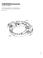
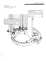
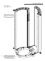
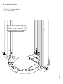
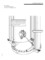
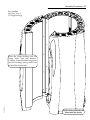
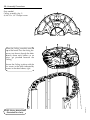
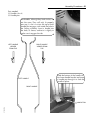
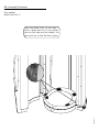
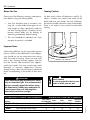
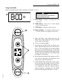
USER MANUAL
27342-01A
Introduction - 1
C
ongratulations on your purchase of this
technologically advanced sun tanning unit.
It has been designed to provide years of
dependable service for you.
Please read all the instructions in this booklet
before installing and using the unit. Always be
sure to observe all safety precautions.
C
ontents
Safety Information . . . . . . . . . . . . . . . . . . . . . . . . . . . . . . .2
Installation . . . . . . . . . . . . . . . . . . . . . . . . . . . . . . . . . . . .4
Pre-Installation Planning . . . . . . . . . . . . . . . . . . . . . . .4
Unpacking and Inspection . . . . . . . . . . . . . . . . . . . . .4
Hardware Inventory . . . . . . . . . . . . . . . . . . . . . . . . . .5
Tools Needed . . . . . . . . . . . . . . . . . . . . . . . . . . . . . . .5
Assembly Procedures . . . . . . . . . . . . . . . . . . . . . . . . .6
Adjusting Hinges . . . . . . . . . . . . . . . . . . . . . . . . . . .24
Stereo Installation . . . . . . . . . . . . . . . . . . . . . . . . . . .25
Electrical Connections . . . . . . . . . . . . . . . . . . . . . . .26
Remote Connections . . . . . . . . . . . . . . . . . . . . . . . . .27
Operation . . . . . . . . .
Before You Tan . .
Exposure Times . .
Tanning Position .
Using Your Booth
.
.
.
.
.
.
.
.
.
.
.
.
.
.
.
.
.
.
.
.
.
.
.
.
.
.
.
.
.
.
.
.
.
.
.
.
.
.
.
.
.
.
.
.
.
.
.
.
.
.
.
.
.
.
.
.
.
.
.
.
.
.
.
.
.
.
.
.
.
.
.
.
.
.
.
.
.
.
.
.
.
.
.
.
.
.
.
.
.
.
.
.
.
.
.
.
.
.
.
.
.
.
.
.
.
.
.
.
.
.
.
.
.
.
.
.
.
.
.
.
.
.
.
.
.
.
.
.
.
.
.30
.30
.30
.30
.31
Care and Maintenance . . . . . . . . . .
Cleaning After Use . . . . . . . . .
Hour Counter . . . . . . . . . . . . .
Thorough Periodic Cleaning . .
Mechanical Inspection . . . . . .
Lamp and Acrylic Replacement
.
.
.
.
.
.
.
.
.
.
.
.
.
.
.
.
.
.
.
.
.
.
.
.
.
.
.
.
.
.
.
.
.
.
.
.
.
.
.
.
.
.
.
.
.
.
.
.
.
.
.
.
.
.
.
.
.
.
.
.
.
.
.
.
.
.
.
.
.
.
.
.
.
.
.
.
.
.
.
.
.
.
.
.
.
.
.
.
.
.
.
.
.
.
.
.
.34
.34
.34
.34
.34
.35
Troubleshooting . . . . . . . . . . . . . . . . . . . . . . . . . . . . . . . .39
Maintenance Schedule . . . . . . . . . . . . . . . . . . . . . . . . . . .42
27342-01A
Technical Diagrams . . . . . . . . . . . . . . . . . . . . . . . . . . . . .43
Warranty . . . . . . . . . . . . . . . . . . . . . . . . . . . . . . . . . . . . .45
2 - Safety Information
LABELING NOTICE: Labels are affixed on all systems to inform the user of possible dangers. Regulations are stated in 21 CFR, Section 1040.20,
and require that all products manufactured after September 8, 1986 which use sunlamps must display the following:
DANGER
Ultraviolet radiation. Follow instructions. Avoid overexposure. As with natural sunlight, overexposure can
cause eye and skin injury and allergic reactions. Repeated exposure may cause premature aging of the
skin and skin cancer. WEAR PROTECTIVE EYEWEAR; FAILURE TO MAY RESULT IN SEVERE BURNS OR LONGTERM
INJURY TO THE EYES. Medications or cosmetics may increase your sensitivity to the ultraviolet radiation. Consult physician
before using sunlamp if you are using medications or have a history of skin problems or believe yourself especially sensitive
to sunlight. If you do not tan in the sun, you are unlikely to tan from the use of this product. Children, the elderly, or fair skinned
people who always burn easily and either never tan or tan minimally should not use this equipment.
For a uniform tan, center yourself within the booth. Other positions may result in overexposure to parts of your body. Do not
use without acrylic panels in place. Untanned persons should not tan on consecutive days during their first week of tanning.
Never tan more than once a day. Tanning normally appears after the first few sessions and maximizes after approximately
four weeks. Tan once or twice per week thereafter to maintain appearance. Persons already having a base tan may begin
at advanced levels corresponding to the extent of their base tan.
RECOMMENDED EXPOSURE TIMES IN MINUTES
Skin Type:
I Sensitive
II Light
III Normal
IV Dark
MAXIMUM EXPOSURE TIME IS 8 MINUTES
Level 1/Week 1 Level 2
1st-3rd Sessions
Skin (Burns easily and severely and does not tan.)
(Burns easily and severely and tans minimally.)
(Burns moderately and tans average.)
(Burns minimally, tans easily and above average.)
Level 3
Level 4
Subsequent
Maximum
NOT RECOMMENDED FOR TANNING
2
3
5
7
3
4
6
8
4
5
7
8
8
8
8
New lamps emit approximately 10% more ultraviolet radiation during the first 50 hours of operation. Recommended tanning
times should therefore be reduced by approximately 10% during that period.
WARNING: • Read the instructions booklet before using this sunlamp product. • All persons in the room should wear protective eyewear when lamps are on. Recommended eyewear: provided eyeshields or equivalent eyewear as defined under
21 CFR 1040.20. Other types of eyewear may not provide adequate protection. Failure to use protective eyewear may result
in severe burns or other eye injury. If discomfort develops, discontinue use and consult a physician.
ONLY THE FOLLOWING LAMPS HAVE BEEN CERTIFIED FOR USE IN THE ELITE 756V:
BRONZING SUN™ GOLD Wolff® Model BSG 79-T12-200W VS-R BI-PIN
DISCONNECT POWER BEFORE ATTEMPTING TO CLEAN, RELAMP,
OR ENGAGE IN THE MAINTENANCE OF THIS PRODUCT.
THIS EQUIPMENT MUST BE EARTH GROUNDED.
This product is in conformity with performance standards for sun lamp products under 21 CFR PART
1040.20 and ANSI/UL Standard 482. Certified to CAN/CSA Standard C22.2 NO. 224.
27342-01A
88465
Renseignements sur la Sécurité - 3
Rayonnement ultraviolet. Veuillez suivre les instructions. Évitez une exposition excessive; tout comme
pour les rayons du soleil, une exposition excessive peut causer des blessures aux yeux et à la peau
et provoquer des réactions allergiques. Une exposition répétée peut causer le vieillissement prématuré de la peau et provoquer le cancer de la peau. PORTEZ DES LUNETTES PROTECTRICES: LE NON-RESPECT DE CETTE CONSIGNE DE
SÉCURITÉ PEUT ENTRAÎNER DE GRAVES BRÛLURES OU DES LÉSIONS OCULAIRES À LONG TERME. Les médicaments ou les produits cosmétiques peuvent augmenter votre sensibilité au rayonnement ultraviolet. Consultez un médecin
avant d’utiliser la lampe solaire si vous prenez des médicaments, si vous souffrez d’une maladie cutanée ou si vous croyez
être particulièrement sensible aux rayons du soleil. Si vous ne bronzez pas au soleil, il est peu probable que vous bronzerez sous une lampe solaire. Les enfants, les personnes âgées et les personnes qui ont une peau claire qui brûle facilement, ne bronze jamais ou alors très peu, ne devraient pas utiliser cette lampe.
DANGER
Pour un bronzage uniforme, placez-vous au centre du compartiment. Un mauvais alignement peut causer une exposition
excessive de certaines parties du corps. N’utilisez pas la lampe sans les panneaux de plastique transparents. La première
semaine de bronzage, les personnes qui n’ont pas un hâle initial ne doivent pas se faire bronzer tous les jours. Ne vous faites
jamais bronzer plus d’une fois par jour. Le bronzage commence normalement à apparaître après les premières séances : il
atteint son apogée au bout d’environ quatre semaines. Les personnes qui ont déjà un teint hâlé peuvent commencer à des
niveaux plus élevés, selon l’importance de leur hâle initial.
TEMPS D’EXPOSITION RECOMMANDÉ EN MINUTES
Type de peau:
I Peau sensible
II Peau claire
III Peau normale
IV Peau foncée
LE TEMPS D’EXPOSITION MAXIMAL EST DE 8 MINUTES
Élevé 1/Semaine 1 Élevé 2
1st-3rd Sessions
(brûle facilement et ne bronze pas)
(brûle facilement et bronze très peu)
(brûle et bronze de façon modérée)
(brûle très peu, bronze plus facilement que la moyenne)
2
3
4
Élevé 3
Élevé 4
Sem. suivantes
Temps maximal
NON RECOMMANDÉ
3
5
7
4
6
8
5
7
8
8
8
8
Les lampes neuves émettent approximativement 10 % de plus de rayons ultraviolets au cours des 50 premières heures de
fonctionnement. Le temps de bronzage doit donc êatre réduit d\rquote environ 10 % pendant cette période.
AVERTISSEMENT : • Lisez le livret d’instructions avant d’utiliser cette lampe solaire. • Les autres personnes présentes
dans la pièce doivent aussi porter des lunettes protectrices lorsque les lampes sont allumées. Coquilles de protection pour
les yeux recommandées: Les coquilles de protection fournies ou l’équivalent, tel que le stipule le document 21 CFR
1040.20. Les autres types de lunettes protectrices peuvent ne pas assurer une protection adéquate. Utilisé sans lunettes
protectrices, ce produit peut causer des brûlures ou lésions oculaires graves. Si vous souffrez d’un malaise, arrêtez l’utilisation et consultez un médecin.
SEULES LES LAMPES INDIQUÉES CI-DESSOUS ONT ÉTÉ HOMOLOGUÉES POUR CET ÉQUIPEMENT:
BRONZING SUN™ GOLD Wolff® Modèle BSG 79-T12-200W VS-R BI-PIN
Débrancher l’alimentation électrique avant de nettoyer l’appareil ,
d’en faire l’entretien ou de changer les lampes.
Cet équipement doit être mis à la terre.
27342-01A
Ce produit est conforme aux normes de rendement pour les lampes solaires dans le documents 21
CFR, partie 1040.20 , ANSI/UL 482 , CAN/CSA C22.2 N° 224.
88465
4 - Pre-Installation Planning
Pre-Installation Planning
Before your booth is installed, you should observe the following considerations.
DANGER
Shock hazard.
Disconnect power before
servicing.
WARNING
Always wear protective eyewear when unit
is on.
Failure to may result in severe burns or
longterm injury to the eyes.
CAUTION
Use of a voltage source above 230V AC
(with unit running) may prevent proper operation of the unit and could cause damage
and void the warranty.
CAUTION
Air from the room is used to cool the unit.
Maximum ambient room temperature
should be 80°F. Place your booth no closer
than 6” from walls. Make sure nothing
obstructs the airflow into or out of the fan
openings. A poorly ventilated room may
cause the unit to become hot and cause
discomfort to the user.
CAUTION
Proper assembly of your booth requires at
least three people. Plan to have a few
helpers assist you.
• The ELITE 756V requires a dedicated circuit
capable of providing either 40 Amp, 3-phase
service (3 wire plus ground) or 69A, 1-phase
service (2 wire plus ground) at 220VAC. This
unit must be hardwired directly to a junction
box on a dedicated circuit. We recommend
connection by a professional electrician.
Consult local and/or national codes for proper
circuit breaker and wire gauge.
The ELITE 756V arrives in eight boxes. For ease of
assembly, after inspection leave everything in its
original box until called for in the assembly
instructions.
Open each box and inspect the contents to make
sure they are free from any visible damage. Report
the extent of any damage to the transportation
company.
Note! The cartons are reusable. You may wish to
save them for future use.
As you unpack your boxes you should find the following:
• Right Module (box 1)
• Bag containing necessary assembly hardware, and safety goggles (box 1)
• Left Module (box 2)
• Right Door (box 3)
• Left Door (box 4)
• Dome and ceiling assembly (box 5)
• Stereo and installation kit (box 5)
• Two blower assemblies (box 6)
• Base (box 7)
• Two Long Interior Handles (box 8)
• Control Extrusion with keypad (box 8)
Record the serial number of the Right Module in
the area provided at the back of this manual. This
information will be required if you ever need to
call customer service.
27342-01A
• IMPORTANT! Operating voltage must be
below 230V AC or may require a Buck
Booster.
Unpacking and Inspection
Unpacking and Inspection - 5
Hardware Inventory
Make sure you have all of these items before
beginning assembly.
x 10
Bolt, 5/16”-18 x 1”
x 10
Washer, 5/16” flat
x2
Lower Handle Bracket
x 12
Screw, #8-32 x 3/4”
x1
x1
Acrylic Key
x1
Remote Control
Bypass Plug
x1
Protective Eyewear
Module Strap
Tools Needed
x4
x2
Screw, #10 x 1”
Phillips pan head
You will need the following tools to assemble the
tanning booth.
Screw, #10 x 1/2”
slotted hex washer head
x4
Hinge Bushing
Wrenches or ratchet wrenches
in 5/16” and 1/2” sizes
x4
Hinge Locking Pin
x6
Screw, #10 x 1”
Phillips flat head
x2
Handle Pin
27342-01A
#2 Phillips screwdriver
x4
Bolt, 1/4-20 x 5/8”
Phillips pan head
6 - Assembly Procedures
Assembly Procedures
Put the Base (found in box 7) in the general area
you want the booth. Leave some space around the
base to work.
BACK
FRONT
27342-01A
Assembly Procedures - 7
Note on assembly:
These instructions illustrate how to assemble
the booth without removing the acrylics.
However, you may find it easier to remove
the acrylics before beginning.
The Left Module is shown at right. Using the
acrylic key (included in the hardware kit)
turn the four quarter-turn latches on the
acrylic to unlock it. 1Swing the acrylic
open, 2lift it and 3pull the bottom out.
27342-01A
To replace the acrylic, insert the top hinge
pin in the hole at the top of the module,
swing the bottom pin into place and drop it
down to engage the pin.
NOTE: Wiring deleted from
illustration for clarity.
8 - Assembly Procedures
Parts needed:
Left Module (box 2)
Stand the Left Module
on the Base as shown.
The tab on the module fits
into the indentation in the
base for easy positioning
27342-01A
NOTE: Wiring deleted from
illustration for clarity.
Assembly Procedures - 9
Parts needed:
(5) 5/16-18 x 1” Hex-head bolts
(5) 5/16” Flat washers
1
Open the acrylic:
Using the acrylic key (in hardware
kit) turn the four latches on the
acrylic to unlock it. Swing the
acrylic open.
27342-01A
2
Secure the Left Module to the Base
with the five bolts and washers in the
slotted holes. (one hole not visible in
illustration because of acrylic)
10 - Assembly Procedures
Parts needed:
(1) Lower handle bracket
(3) #8-32 x 3/4” Phillips pan-head thread cutting screws
Locate the three holes in the bottom
plate of the Left Module. Position the
Lower Handle Bracket underneath
the bottom plate and attach with the
three screws as shown.
Close and lock the acrylic.
27342-01A
Assembly Procedures - 11
Parts needed:
Right Module (box 1)
27342-01A
Stand the Right Module
on the Base as shown.
NOTE: Wiring deleted from
illustration for clarity.
12 - Assembly Procedures
Parts needed:
(5) 5/16-18 x 1” Hex-head bolts
(5) 5/16” Flat washers
Just like the Left Module, open the
acrylic and secure the Right
Module to the Base with the
remaining five bolts and washers.
27342-01A
Assembly Procedures - 13
Parts needed:
(1) Lower handle bracket
(3) #8-32 x 3/4” Phillips screws
Locate the three holes in the bottom
plate of the Right Module. Position
the Lower Handle Bracket underneath
the bottom plate and attach with the
three screws as shown.
27342-01A
Close and lock the acrylic.
14 - Assembly Procedures
Parts needed:
(1) Module Strap
(2) #10 x 1” Phillips pan head screws
Connect the two modules with
the Module Strap, as shown.
27342-01A
NOTE: Wiring deleted from
illustration for clarity.
Assembly Procedures - 15
Parts needed:
Control Extrusion (box 8)
(2) #10 x 1” Phillips pan head screws
(2) #10 x 1/2” slotted hex washer head
screws
1
Feed the cable from the Control
Extrusion through the hole between
the modules.
2
Press the Control Extrusion into
place and secure the top with the
pan head screws.
27342-01A
3
Secure the bottom of the
extrusion with the hex head
screws. Use a 5/16” wrench
or ratchet.
NOTE: Wiring deleted from
illustration for clarity.
16 - Assembly Procedures
Parts needed:
Right Door (box3)
(2) Hinge bushings
HINGE PIN
HINGE BUSHING
FRICTION TAB
LOWER HINGE
Place the Hinge Bushings into the
hinge holes (top and bottom).
Carefully lower the door hinge pins
into the bushings, being careful not
to bend the friction tabs.
27342-01A
NOTE: Wiring deleted from
illustration for clarity.
Assembly Procedures - 17
Parts needed:
Left Door (box 4)
(2) Hinge bushings
27342-01A
Place the Hinge Bushings into the
hinge holes (top and bottom).
Carefully lower the door hinge pins
into the bushings, being careful not
to bend the friction tabs.
NOTE: Wiring deleted from
illustration for clarity.
18 - Assembly Procedures
Parts needed:
Ceiling assembly (box 5)
(6) #8-32 x 3/4” Phillips screws
Lower the Ceiling assembly onto the
top of the booth. Pass the wiring harnesses (not shown) through the holes
directly above each harness so no
wires get pinched beneath the
Ceiling.
Secure the Ceiling in place with the
six screws in the holes indicated by
arrows in the detail above, right.
27342-01A
NOTE: Wiring deleted from
illustration for clarity.
Assembly Procedures - 19
Connect the wiring harnesses as shown.
Match similarly colored harnesses and
plug them together firmly. Use care
when plugging into the display board.
FROM CONTROL
EXTRUSION
DISPLAY BOARD
FROM RIGHT
MODULE
27342-01A
STEREO WIRE
FROM LEFT DOOR
20 - Assembly Procedures
Parts needed:
Dome (box 5)
(6) #10 x 1” Phillips flat head screws
Lower the Dome onto the booth.
Use the six screws to secure it.
27342-01A
Assembly Procedures - 21
Parts needed:
(2) Handles (box 8)
(2) Handle pins
The handles, although they look similar, are
not the same. They will only fit properly
one way. A slot is cut into the top of each
handle that engages a tab inside the hole in
the Ceiling assembly. Insert a handle into
the hole, as shown, and twist it slightly to
make sure it engages the tab.
LEFT HANDLE
VIEWED
FROM TOP
RIGHT HANDLE
VIEWED FROM
TOP
LEFT HANDLE
Slide the bottom of the handle into
the lower handle bracket and insert
a handle pin through it to lock the
handle in place.
RIGHT HANDLE
27342-01A
HANDLE PIN
22 - Assembly Procedures
Parts needed:
Booth Floor (box 7)
Place the Booth Floor on the Base. It
locks in place with two 1/4 turn latches,
one on each side near the handles. Use
the acrylic key to lock the floor in place.
27342-01A
Assembly Procedures - 23
Parts needed:
Blowers (box 6)
(4) 1/4-20 x 5/8” Phillips pan head bolts
The Blower assemblies hook on
the base and pivot into position
(see detail below). Secure them
in place with the bolts.
27342-01A
Plug the cables from the
booth into each Blower.
24 - Adjusting Hinges
Adjusting Hinges
Parts needed:
(4) Hinge locking pins
The booth doors should close tightly, with an even
seam between them. The hinges adjust to correct
any door alignment problems. Loosen the lock
nuts on the underside of a hinge (see photo) and
adjust the door as needed. Tighten the lock nuts
when the doors are adjusted properly.
Insert the Hinge Locking Pins into the Hinge Pins
to prevent the doors from lifting off.
LOCK NUT
HINGE PIN
HINGE LOCKING PIN
27342-01A
Stereo Installation - 25
Stereo Installation
27342-01A
The ELITE 756V is designed to accept a stereo in
the left door. Box 5 contains a stereo installation
kit, complete with stereo and power supply.
Follow the instructions included with that kit to
install the stereo. The ceiling of the booth contains
speakers.
26 - Electrical Connections
Electrical Connections
On the back of the booth is a junction box. Have
your electrician connect power directly into this
box as described in Pre-Installation Planning.
Again, a professional electrician is recommended.
Your booth is designed to work with a remote control device. Three remote ports are located on
back of the booth, two RJ-22 (4-wire) ports and
one RJ-11 (6-wire) port. If you choose not to use a
remote, insert the Remote Control Bypass plug
into either of the smaller remote control ports as
shown. Your booth will not operate without the
Remote Control Bypass plug or a remote system
connected. Your equipment is now ready for use.
NOTE: Your unit is designed to accept an input
from a remote control device. The remote control is optional. If you plan on using a remote system refer to Remote Connections.
ATTENTION: Although the Remote Control
Bypass plug provided with your unit will work
wherever a T-Max® terminator is called for in the
series, the T-Max® terminator will not work as a
bypass plug. A bypass plug is needed only when
your booth is operated without a remote system
connected.
In the ceiling of the booth are two speakers capable of handling 25W of musical power, with a
maximum of 120W. Next to the remote control
ports are two speaker inputs to connect to a
stereo.
REMOTE CONTROL
BYPASS PLUG
REMOTE CONTROL
PORTS
JUNCTION BOX
(Stereo Power Supply
not shown)
27342-01A
Remote Connections - 27
Remote Connections
Your tanning booth incorporates advanced circuitry allowing it to connect and communicate with
most remote control systems. If a remote system
is to be used, first determine whether the remote
system is a T-Max® System or a standard remote
system operating with a control relay. Follow the
appropriate instructions for your system type.
CAUTION
The remote connection is not designed to supply
or accept high voltage, nor can it provide power
to an external timer. The sunbed’s remote interface circuitry operates on 5 volts, attempting to
connect it to any higher voltages will damage the
sunbed as well as void your warranty.
T-Max® Products
The T-Max® remote systems offer the ultimate in
sunbed control, while allowing the tanner easy
straightforward operation. Your sunbed is configured to directly connect to this system, including
the new wireless remote system. The circuitry
inside your sunbed eliminates the need for the TMax® 1A or 3A when connecting to the T-Max®
Manager series. Your sunbed supports the auto
addressing feature of the latest T-Max® Manager
models and the following parameters: 5, 6, 7, 8, 9,
10, 15 and 23. See your T-Max® manual for
descriptions of these parameters and how they
function.
27342-01A
Go straight to the source with all your T-Max®
brand remote questions: (417) 338-5101
REMOTE PORTS
WIRED
REMOTE
PORTS (RJ-22)
WIRELESS
REMOTE
PORT (RJ-11)
T-Max® Wireless Remote System
The T-Max® AP-900 eliminates wires in your
salon, allowing easy setup without hiring an electrician to run wires. It also protects your investment from damage by isolating each unit from one
another. Your sunbed arrives “wireless ready”,
which means it connects directly to the T-Max®
wireless system.
The T-Max® wireless system is available in two
configurations: AP-900 Retail and AP-900 OEM.
The Retail version contains a power adapter
which plugs into a standard 110V outlet. The OEM
version gets power from the tanning bed through
the same RJ-11 cable it uses to communicate,
eliminating the need for an outlet. Tanning beds
labelled “wireless ready” use the AP-900 OEM.
Auto Addressing with T-Max®
Your T-Max® Manager manual will explain how to
get into auto address mode. Once auto address has
been activated, your booth display will blink “88”.
Wait 10 seconds for the system to communicate
properly and press the START button. The booth
will flash “99” to signify it has accepted the
address and return to “0:00”.
Remote System Hook-up Scenarios
Follow the diagrams on the following pages to see
the many different scenarios for hooking up your
salon. If you need further assistance, call T-Max®
directly at (417) 338-5101.
28 - Remote Connections
Scenario 1 - T-Max® Manager Series with wires
This system is ideal for multiple sunbed installations.
Simply connect the RJ-22 modular cable(s), described
in the T-Max® Manager manual, into the remote port(s)
located on the back of your booth and follow the
instructions that came with your remote system. If you
have an older T-Max® Manager that does not support
auto addressing, set the address of each unit manually
as described in Setting the address manually. You can
place your booth at any location in the series.
Scenario 2 - Single Booth wired to T-Max® 3A
In single sunbed installations, the T-Max® 1A and 3A
can offer the same control as the T-Max® Manager,
eliminating the need for a Manager. If you’re using a
1A in this manner, it must have a chip labelled “master” installed on its circuit board. The remote control
bypass plug must not be used in this configuration. The
3A may be used as a “master” with no modification.
After you have set the T-Max® 1A’s, or 3A’s, address to
“0” (refer to your T-Max® user’s guide) and the booth’s
address to “1”, simply connect the RJ-22 modular
cables, described in the T-Max® user’s guide, directly
into either of the smaller ports located on the back of
the booth and either port on the back of the T-Max® 1A
or 3A.
NOTE: A T-Max® 1A with a
“master” chip can be substituted
for a 3A.
Scenario 3 - T-Max® Manager Series with
Complete Wireless
Connect one AP-900 Retail to the Manager and one
AP-900 OEM to each of the tanning unitss. Install as
many units as you like with this configuration. Units
that do not communicate with T-Max will need an
AP-900 Retail and an additional 3A to operate.
Scenario 4 - T-Max® Manager Series with
Wireless combo
27342-01A
Connect one AP-900 Retail to the Manager and
one AP-900 OEM to a wireless ready tanning unit.
The rest of the salon may be “daisy-chained”
together and connected to the wireless equipped
tanning unit, eliminating the need to wire the
Manager to the tanning equipment.
Remote Connections - 29
Scenario 5 - T-Max® Manager Series with Wireless
combo 2
Wireless can be easily added to an existing salon already
utilizing T-Max®. Connect one AP-900 Retail to the
Manager and one AP-900 OEM to each wireless ready
tanning unit. The rest of the salon may be “daisy-chained”
together and connected to the Manager.
Scenario 6 - T-Max 3A with Wireless
Connect one AP-900 Retail to the T-Max® 3A
and one AP-900 OEM to the booth in single
unit installations.
Scenario 7 - Non T-Max® Remote System wired
to unit
Most non-T-Max® remote systems control the unit by
the use of a relay. The relay operates the unit by connecting and disconnecting a pair of wires leading from
the unit. Refer to the user’s manual provided with your
remote system to determine if it operates in this way.
The unit will begin a full session when the remote is
activated. To connect your booth to this type of system
a remote interface kit is required. Contact your place
of purchase to obtain the kit. Follow the instructions
provided with the kit and from the remote’s manual to
make the necessary connections.
Setting the address manually
Before connecting your booth to the T-Max®
Manager or T-Max® 1A or 3A, the address of your
booth must first be set. Set the “id” manually as
described below.
Setting the Address
1. Make sure the booth display is showing
“0:00”.
2. Press the STOP button for three seconds. The
display should indicate an address number
from “1” to “255”.
3. If you are using a T-Max® 1A or 3A as a
“master” remote, the address of the booth
must be set to “1”. If you are using a T-Max®
Manager each sunbed must be assigned a
different address. To adjust the address, press
the up arrow button to count up until the
desired number (from 1 to 128) is achieved.
Press the down arrow button to count down
to the desired number. Addresses 252 to 255
are not normally used.
4. Press the STOP button to return to the normal display mode.
27342-01A
CAUTION
The remote connection is not designed to supply
or accept high voltage, nor can it provide power
to an external timer. The booth’s remote interface circuitry operates on 5 volts, attempting to
connect it to any higher voltages will damage the
unit as well as void your warranty.
30 - Operation
Before You Tan
Tanning Position
Please note the following warnings and precautions before using your tanning booth.
For best results, follow all directions carefully. To
obtain a uniform tan, stand in the center of the
booth and raise your hands. You may hold onto
the interior handles wherever it feels comfortable.
There is no need to turn yourself around while
tanning.
• Your skin should be free of cosmetics, tanning oils, or other body lotions prior to tanning except for those specifically made for
use with tanning devices. However, do not
remove natural body oils by bathing or
showering immediately before tanning.
• This unit intended for individual use. Only
one pair of eyewear is included.
Exposure Times
Follow the guidelines for skin type and exposure
times as shown in the table below. Untanned persons should not tan on consecutive days during
their first week of tanning. Never tan more than
once a day. Tanning normally appears after the
first few sessions and maximizes after approximately four weeks. Tan once or twice per week
thereafter to maintain appearance. Persons
already having a base tan may begin at advanced
levels corresponding to the extent of their base
tan.
DANGER
DANGER
Shock hazard.
Do not operate this device near
water or while you are wet.
Some medication may increase your sensitivity to ultraviolet light. It is recommended
that you consult a physician before using
this equipment if taking any medication or
if you suspect that your skin might be
especially sensitive to sunlight.
RECOMMENDED EXPOSURE TIMES IN MINUTES
Level 1/Week 1 Level 2
1st-3rd Sessions
Skin (Burns easily and severely and does not tan.)
(Burns easily and severely and tans minimally.)
(Burns moderately and tans average.)
(Burns minimally, tans easily and above average.)
Level 3
Level 4
NOT RECOMMENDED FOR TANNING
2
3
5
7
3
4
6
8
4
5
7
8
Subsequent
Maximum
8
8
8
27342-01A
Skin Type:
I Sensitive
II Light
III Normal
IV Dark
MAXIMUM EXPOSURE TIME IS 8 MINUTES
Using Your Booth - 31
Using Your Booth
When connected to the T-Max® Manager or T-Max® 1A or 3A.
WARNING
A
Wear protective eyewear.
Failure to may result in severe burns or
longterm injury to the eyes.
A Timer display - Displays remaining time and
fan status.
B START button - Turns unit on. Timer display
shows remaining time.
C STOP button - Interrupts tanning session.
D Body fan buttons - Turns body cooling fans on
and off. Indicator on display shows status.
B
1. Open the doors, step inside and close the
doors fully. For best results, position your body
in the center of the booth.
2. Put on your safety goggles.
D
3. Assuming the remote system has been set to
allow a pre-tanning delay time, the timer display (A) will count down the remaining delay
time. Press the START button (B) or wait until
the delay time has expired to begin the tanning
session. The lamps will turn on and the timer
will begin to count down.
4. When the timer reaches 0 the lamps turn off. If
you want to stop your session before time
expires, press the STOP button (C).
5. Exit the booth. The cooling fans run for a period of time after the lamps shut off to aid in
cooling the booth. The timer will indicate “:”
as a reminder to clean the tanning surfaces.
After the booth is cleaned, press the START
button and the display will return to “0:00”.
27342-01A
C
32 - Using Your Booth
Using Your Booth
When connected to a remote system using a control relay.
WARNING
A
Wear protective eyewear.
Failure to may result in severe burns or
longterm injury to the eyes.
A Timer display - Displays remaining time and
fan status.
B START button - Turns unit on. Timer display
shows remaining time. If a lesser time is
desired, press START button until desired
time is displayed.
B
C STOP button - Interrupts tanning session.
D Body fan buttons - Turns body cooling fans on
and off. Indicator on display shows status.
1. Open the doors, step inside and close the
doors fully. For best results, position your body
in the center of the booth.
2. Put on your safety goggles.
D
3. As soon as the remote timer is activated the
unit starts at the maximum time. The lamps
will turn on and the timer will begin to count
down.
4. If a tanning time less than the displayed time is
desired, repeatedly press the START button (B)
to decrease the remaining time.
5. When the remote timer expires, or the booth
timer reaches 0, the lamps turn off. If you want
to stop your session before time expires, press
the STOP button (C). You will have ten seconds
to restart with the remaining time, otherwise
the timer will reset to 0:00.
6. Exit the booth. The cooling fans run for a period of time after the lamps shut off to aid in
cooling the booth.
C
27342-01A
Using Your Booth - 33
Using Your Booth
When used as a stand alone unit.
WARNING
A
Wear protective eyewear.
Failure to may result in severe burns or
longterm injury to the eyes.
A Timer display - Displays remaining time and
fan status.
B START button - Turns unit on. Timer display
shows remaining time. If a lesser time is
desired, press START button until desired
time is displayed.
B
C STOP button - Interrupts tanning session.
D Body fan buttons - Turns body cooling fans on
and off. Indicator on display shows status.
1. Open the doors, step inside and close the
doors fully. For best results, position your body
in the center of the booth.
2. Put on your safety goggles.
3. Press the START button (B) to begin the tanning
session. The lamps will turn on and the timer
will begin to count down.
D
4. If a tanning time less than the displayed time is
desired, repeatedly press the START button (B)
to decrease the remaining time.
5. When the timer reaches 0 the lamps turn off. If
you want to stop your session before time
expires, press the STOP button (C). You will
have ten seconds to restart with the remaining
time, otherwise the timer will reset to 0:00.
6. Exit the booth. The cooling fans run for a period of time after the lamps shut off to aid in
cooling the booth.
27342-01A
C
34 - Care and Maintenance
Cleaning After Use
Clean and disinfect the acrylics, floor and handles
after each use. Use a non-abrasive disinfectant
cleaner that does not contain ammonia or ammonia derivatives. Ammonia may damage the acrylic
shield. Spray the acrylic lightly with disinfectant
and wipe dry with a clean soft cloth. We recommend Australian Gold® pH Neutral Disinfectant
Cleaner.
WARNING
Shock hazard.
Disconnect power before removing
any protective covers.
Hour Counter
Your booth is equipped with an hour counter that
tracks how long the unit has been in service,
much like your vehicle’s odometer. The hour
counter is located on the top of the right blower,
behind the unit. Use this counter to track lamp
hours and many other time based maintenance
procedures.
Thorough Periodic Cleaning
Introduction
The cooling fans draw air through the booth and
over time will cause a dust buildup on the lamps
and reflectors. This will reduce the tanning effectiveness of the unit. When a dust buildup is
observed, it is necessary to thoroughly clean the
inside of the booth.
• Open the acrylic shields and remove lamps as
described in Lamp and Acrylic Replacement.
• With a soft cloth, wipe the entire length of each
lamp to remove any film buildup.
• Clean both sides of the acrylic shields with a
non-ammonia disinfectant cleaner.
• Wipe the reflectors with a clean damp cloth.
• Reinstall the lamps and acrylic shields.
• Replace air filters inside each blower. Replace
with a 12” x 12” x 1” furnace filter.
Mechanical Inspection
Your tanning booth has been built for years of
service. To ensure trouble-free operation throughout its life, inspect the unit’s mechanical integrity
every 400-500 hours of use.
• Inspect the unit’s fasteners verifying that all are
firmly in place.
• Inspect door alignment. Adjust hinges so doors
close tightly with an even seam between them.
See Adjusting Hinges.
• Inspect all power cords and connections.
• Inspect the acrylics. Broken, cracked or badly
scratched acrylics should be immediately
replaced.
27342-01A
Lamp and Acrylic Replacement - 35
Lamp and Acrylic Replacement
Introduction
To be assured of maximum tanning effectiveness,
change lamps after approximately 500-700 hours
of use. Tanning will continue after this time but at
a slower rate. To ensure trouble-free operation of
your booth, replace the lamp starters whenever
the lamps are replaced.
WARNING
Shock hazard.
Disconnect power before removing
any protective covers.
Opening/Replacing Acrylic Shields
Each acrylic shield is secured in place by four
quarter-turn latches. The Left Module is shown at
right. Using the acrylic key (included in the hardware kit) remove the floor. Then use it to unlock
the acrylic. 1Swing the acrylic open, 2lift it and
3pull the bottom out.
To replace the acrylic, insert the top hinge pin in
the hole at the top of the module, swing the bottom pin into place and drop it down to engage the
pin.
CAUTION
27342-01A
Be careful. The edges of the acrylic shield
may be sharp.
36 - Lamp and Acrylic Replacement
Removing/Replacing Main Lamps
After opening the acrylic, grasp a lamp at one end
and at the middle and turn the lamp one quarter
turn. Gently remove the lamp from its holders.
Reinstall the lamp by inserting the pins located on
the ends of the lamp into the slots on top of the
lamp holders and turn the lamp a quarter turn. It
should click in place.
Removing/Replacing Main Lamp Starters
The top of the starter is visible after removing a
lamp. There is one starter for each lamp. Grasp the
starter and turn it gently. It will click loose and pull
out easily.
Reinstall the starter by inserting the pins located
on the bottom of the starter into the holes in the
starter holder and turning. It should click in place.
Recommended Replacement Lamps
We recommend using the lamps specified below.
Use of uncertified lamps is a violation of Federal
regulations and will void your warranty. These
lamps have an average life of 500-700 hours of
effective tanning use. Lamps used longer than that
begin to lose their effectiveness even though they
continue to light.
Recommended Replacement Acrylics
Acrylics vary greatly over time in their ability to
effectively transmit UV light. Acrylics sold by ETS
have been life tested to ensure proper transmission throughout their useful life.
ONLY THE FOLLOWING LAMPS HAVE BEEN CERTIFIED FOR USE IN THIS EQUIPMENT:
BRONZING SUN™ GOLD Wolff® Model BSG 79-T12-200W VS-R BI-PIN
27342-01A
Lamp and Acrylic Replacement - 37
SCREWS
Replacing Decorative Door Lamps
Inside each door is a small fluorescent lamp
which illuminates the decorative window. To
access these lamps you must first remove the door
acrylic and the first 8 lamps (starting from the handle side). Follow these directions carefully.
Behind the door lamps are two, side-by-side
reflectors (the left door is shown at left). Remove
the one closest to the handle side by unscrewing
the four screws holding it in place. This will reveal
the decorative lamp access panel (below center).
TOP
BOTTOM
The decorative lamp access panel is held in place
by three screws. Removing this panel exposes the
decorative lamp and its starter (below right).
Replace both of them at the same time.
Reverse the above directions to reassemble the
door.
Replace the lamps with a 25Watt, 36”, T8 lamp.
SCREWS
27342-01A
SCREWS
38 - Lamp and Acrylic Replacement
Replacing Entry Lamps
Above the doors are two small fluorescent lamps
to illuminate the inside of the booth when the tanning lamps are off. To access these lamps you
must first remove the Dome. Follow these directions carefully.
Unscrew the six screws around the Dome. Lift the
Dome off the unit.
On the front of the ceiling assembly is an oddly
shaped metal panel (see below). Four screws hold
it in place. Remove the screws and carefully lift
the panel. Be careful not to pull on the wires running through the panel. Turn it over to reveal the
lamps (right).
Grasp the lamp by its base, not the lamp glass,
and pull it straight out of the lamp holder. Replace
the lamp by lining up the pins on its base with the
lamp holder and pressing it firmly into place.
Reverse the above directions to reassemble the
Dome.
Replace with Philips Alto PL-C 26W/35/2P or
equivalent.
27342-01A
NOTE: Wiring deleted from
illustration for clarity.
Troubleshooting - 39
Problem
Cause
Booth not tanning
1. Booth dirty
2. Low voltage
3. Lamps old
4. Acrylics scratched
1. Clean booth, see Thorough Periodic Cleaning.
2. Ensure supply voltage is between 208 and
230V AC.
3. Replace lamps if lamp hours are greater than
700hrs.
4. Replace acrylic.
Lamps fail to light and timer 1. Unit unplugged
display is blank
2. Circuit breaker
tripped
1. Make sure the unit is connected to a power
source.
2. Check source of AC power. Reset circuit breaker or replace fuse.
One or more lamps fail to 1. Lamp loose
2. Lamp burnt out
light
1. Check that lamp is installed correctly.
2. Switch unlit lamp with a lamp that lights, if
new lamp lights and old lamp still does not,
replace old lamp.
Booth getting too hot
1. Not enough airflow 1. Turn body fan on.
2. Salon too hot
2. Ambient temperature of salon room must be
below 80° at all times.
3. Air filters clogged
3. Check air filters. Change if dirty.
4. Voltage too high
4. Input voltage, with unit running, must be less
than 230VAC.
Body cooling fans won’t Temperature sensor on
timer board indicated
turn off
unit is too hot and
turned the fans on.
27342-01A
Solution
None. Timer display will show blinking fan
indicator when timer board has activated
fans. They cannot be turned off until unit
cools down.
E 91 showing on display
Timer computer not
functioning properly
E 92 showing on display
Current sensor indicating unit is off when it
should be on
Contact servicer.
E 93 showing on display
Current sensor indicating unit is on when it
should be off
Contact servicer.
E 98 showing on display
Unit temperature
exceeded
1. Disconnect then reconnect power to reset
timer.
2. Contact servicer to replace main timer.
1. Allow unit time to cool.
2. Check all fan openings and air filters for
obstructions.
3. If problem persists, contact servicer.
40 - Troubleshooting
Problem
Cause
I forgot what address I set
my sunbed to
Solution
By holding the STOP button for 3 seconds the
timer display will briefly blink “id” and your
address number.
Timer display changes to 1. Bypass plug not
indicate a tanning time
installed
after the START button is 2. A non-SunStar®
pressed but lamps do not
bypass has been
come on
used
3. Remote not set
4. Remote wiring
incorrect
My bed is connected to the Auto-start not on
T-Max® Manager remote
system and when the delay
time has expired the timer
display starts counting
down but the booth lights
do not come on
1. See Electrical Connections.
2. See Electrical Connections.
3. If remote is being used, other than T-Max®
Manager, the external timer may not be activated.
4. See the instructions provided with the remote
interface kit.
The auto start feature of the remote system is
disabled, see the instructions provided with
your remote system.
1. The booth must first be set to a unique
My booth won’t work with 1. Address incorrect
address, see Remote Connections.
the T-Max®
Manager
2. Terminator plug
2. The bypass or terminator plug may be
remote system
installed incorrectly
installed in the series in an inappropriate
location. Plug the bypass plug only into the
bed at the end of the series.
I frequently disconnect my
sunbeds from the T-Max®
chain and interrupt the rest
of the units
A T-Max® Inline 4-Pin Connector is available
from ETS, Inc. which connects the chain without a sunbed.
Timer display continues to
show 0:00 after the START
button is pressed
1. T-Max® Manager remote system has not yet
been set.
2. Booth address is not set correctly, see Remote
Connections.
27342-01A
Troubleshooting - 41
Problem
Cause
Solution
My booth, connected to a
T-Max® Manager, did not
display a delay time but
does indicate:
1. Remote device has 1. Set remote device.
0:00
not been set
2. See Remote Connections.
2. The booth has not
been connected to
the remote system
1. Set delay time on T-Max® Manager.
a tanning time and the 1. Delay time of Tlamps have come on
Max® Manager has
not been set
2. Set a longer delay time if desired.
2. Delay time has
expired
27342-01A
a tanning time but the Auto-start not on
lamps have not come on
Auto start function of T-Max® Manager has
been turned off. Press the START button to
turn on lamps.
When auto-addressing the
first bed does not register
an address
When using the auto address feature of the TMax® Manager you must wait 10 seconds
from the time you start the auto address function before addressing the first bed.
When using a T-Max® 1A Terminator plugs not
my booth won’t function installed
properly
Remote Bypass plugs or terminator plugs may
be needed if the T-Max® 1A and the booth are
over 100 feet apart. Install the plugs in the
open remote port in the booth and the TMax® 1A.
My salon suffers frequent,
short power outages and
clients complain about losing session time
If you have a T-Max® Manager, changing
parameter 23 from “0” to “1” will allow the
tanning booth to remember how much time
was left when power goes out and resume its
session after power is restored. Consult your
T-Max® Manager manual for information on
setting parameters.
42 - Maintenance Schedule
WHEN
What to do
After each use
A. Clean/Disinfect Interior Surfaces*
Monthly
400-500hrs
500-700hrs
As Needed
✘
B. Clean Lamps*
✘
C. Clean Reflectors*
✘
D. Clean Exterior
✘
E. Check/Clean Fans†
✘
✘
F. Change Lamps and Starters**
✘
G. Change Acrylics**
H. Check Fasteners (nuts, bolts, etc.)*
✘
I. Check Door Alignment***
✘
J. Check Power Cords*
✘
K. Change Blower Filters*
✘
* See Care and Maintenance
** See Lamp and Acrylic Replacement
*** See Adjusting Hinges
† Fans are located on top of each module and door and at the bottom of each door. Use a vacuum to clean.
What
example
B C D E
When
MAINTENANCE LOG
What
When
What
When
4/15
27342-01A
27342-01A
Technical Diagrams - 43
44 - Technical Diagrams
27342-01A
Warranty - 45
STANDARD 48 MONTH WARRANTY
Your tanning unit is warranted to be free of structural defects in material and workmanship, under normal use, for
its lifetime. ETS, Inc. will, at its discretion, repair any structural defect which materially affects the performance of
the tanning unit, or replace the tanning unit.
For forty-eight (48) months following the shipping date of your tanning unit, ETS, Inc. will provide replacements
for parts that prove to be defective in material or workmanship. Fluorescent lamps, and lamp starters are warranted
against manufacturer’s defects for a period of ninety (90) days following the shipping date of your tanning unit.
Acrylics will be warranted against manufacturer’s defects for a period of 2 years (prorated).
Labor costs associated with repair or replacement work covered by this warranty will be reimbursed for repair or
replacement work required to be performed for a period of one (1) year following the shipping date of your tanning unit. Normal wear and tear, damage from misuse or abuse, damage incurred in transit or damages resulting
from unauthorized repairs or modifications are not covered by this warranty. Warranty coverage does not include
cosmetic abnormalities such as scratches, nicks, dents, or other cosmetic changes that do not materially interfere
with the function of the tanning unit.
THIS STANDARD 48 MONTH WARRANTY IS EXPRESSLY MADE IN LIEU OF ANY OTHER WARRANTIES,
EXPRESS OR IMPLIED, INCLUDING ANY IMPLIED WARRANTIES OF MERCHANTABILITY AND FITNESS
FOR A PARTICULAR PURPOSE, WHICH ARE HEREBY DISCLAIMED. No one has the authority to change or
modify this Standard 48 Month Warranty in any respect. To obtain service under this Standard 48 Month Warranty,
contact ETS, Inc. at 1-800-449-3605, and ask for the Technical Service Department. Proof of purchase, including
serial number, is required.
IN NO EVENT SHALL THE MANUFACTURER BE LIABLE AT LAW OR IN EQUITY FOR ANY LOSS, LIABILITY, DAMAGE OR EXPENSE IN AN AMOUNT IN EXCESS OF THE PURCHASE PRICE RECEIVED, OR FOR
LOSS OF USE OR PROFITS, LOSS OF TIME, INCONVENIENCE, RENTAL OR SUBSTITUTE PRODUCTS, LOSS
OF BUSINESS, LOSS OF INCOME, OR ANY OTHER INCIDENTAL, INDIRECT, SPECIAL OR CONSEQUENTIAL DAMAGES. Some states do not allow the exclusion or limitation of incidental or consequential damages, and
the above limitation or exclusion will not apply to residents of some states. This Standard 48 Month Warranty gives
you specific, legal rights and you may have other rights which may vary from state to state.
All warranty service must be performed by an authorized service person. All labor charges must be authorized by
ETS, Inc. prior to the start of repairs and must not exceed the established rates and time allotment policies established by ETS, Inc. If your tanning unit must be returned for service, all freight charges shall be at your expense.
Contact ETS, Inc. for the authorized Service Center nearest you. This warranty is serial number specific and only
applies to tanning units purchased through an authorized ETS Distributor. This warranty is extended to the individual or legal entity whose name appears on the original sales document and may not be transferred to any other
individual or legal entity. This warranty is void if the tanning unit is modified in any manner from its original design.
To file a Warranty Claim, please follow these steps:
1. Locate the silver serial number label, located on the back of the unit near the junction box.
Identify the serial number and model number of the unit.
2. Proof of purchase must be provided before any claim will be considered.
3. Contact ETS, Inc. at 1-800-449-3605.
27342-01A
4. If it is determined that a defective part needs to be replaced, your service representative will
arrange for the pick-up or shipment of the replacement part.
Record this information for ease of service:
Date of purchase:
Serial number:
ELITE 756V
Size
(doors shown closed)
Recommended Room Size
Weight
Electrical Voltage (AC)
Amperage
Outlet
Main Lamps
Ballasts
Body Cooling System
Speakers
Timer System
Max. Exposure Time
Back-up Timer
Remote Capability
(doors shown open)
7’ x 8’ (2.1m x 2.7m)
1045 lbs. (475 kg)
220
40A 3-phase
69A 1-phase
Booth hardwired
56 x BRONZING SUN™ GOLD 200W
200W
2 x high power blowers from base, face blower, overhead fan
2 x 25W (120W max) 2-way speakers
Digital
8 minutes
Digital “watchdog” circuitry
T-Max® compatible
U.S. Patent 6,660,025 B2
CALL FOR SERVICE OR QUESTIONS: 1•800•449•3605
7445 Company Drive, Indianapolis, IN 46237-9296