1
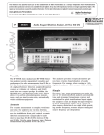
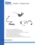
User’s Manual
LR-100 Stationary Receiver / Power Amplifier
Don’t miss a single sound. Listen.
Listen Technologies Corporation
8535 South 700 West, Suite A
Sandy, Utah 84070-2515 USA
Telephone: +1.801.233.8992
Toll Free (North America): 1.800.330.0891
Fax: +1.801.233.8995
E-mail: [email protected]
Welcome to Listen!
Dear Valued Customer,
Thank you for choosing Listen! All of us at Listen are dedicated to providing you
the hightest quality products and prompt, efficient customer care. Our products are
manufactured in an ISO-9000 factory that has been independently certified to the
highest quality standards. We stand ready to answer any questions you might have
during installation or in the operation of our products. Should there be any problems with your Listen products, we are ready to help you in any way we can.
Should you have any comments on how we might improve our products or our
service, we’re here to listen. Here’s how to reach us:
Telephone: +1.801.233.8992
Fax: 1.801.233.8995
Toll Free (North America): 1.800.330.0891
E-Mail: [email protected]
Web: www.ListenTech.com
Thank you... and enjoy your listening experience!
Best regards,
The Listen Team
LR-100 Package Contents
Listen Part Number
·
·
·
·
·
·
·
·
LR-100-072 for 72 MHz
LR-100-216 for 216 MHz
LR-100-072 (72MHz) or
LR-100-216 (216MHz) or
120 VAC Power Supply
LA-123 90 Degree Helical Antenna (72MHz) or
LA-124 90 Degree Helical Antenna (216MHz)
Allan Wrench
Warranty Card
User Manual
Optional Accessories
See page 20
i
Listen™ and the Listen Logo are registered trademarks of Listen Technologies Corporation.
LR-100_2004_08_03 © 2003 Listen Technologies Corporation. All Rights Reserved.
Architectural Specifications . . . . . . . . . . . . . . . . . . . . . . . . . . . . . . . . . . . . . . . . . . .2
Specifications . . . . . . . . . . . . . . . . . . . . . . . . . . . . . . . . . . . . . . . . . . . . . . . . . . . . . . .2
Quick Reference . . . . . . . . . . . . . . . . . . . . . . . . . . . . . . . . . . . . . . . . . . . . . . . . . . . .3
Block Diagram . . . . . . . . . . . . . . . . . . . . . . . . . . . . . . . . . . . . . . . . . . . . . . . . . . . . . .5
Setup . . . . . . . . . . . . . . . . . . . . . . . . . . . . . . . . . . . . . . . . . . . . . . . . . . . . . . . . . . . . .6
Installation . . . . . . . . . . . . . . . . . . . . . . . . . . . . . . . . . . . . . . . . . . . . . . . . . . . . . . . . .7
Speaker Connection . . . . . . . . . . . . . . . . . . . . . . . . . . . . . . . . . . . . . . . . . . . . . . . . .8
Antenna Installation . . . . . . . . . . . . . . . . . . . . . . . . . . . . . . . . . . . . . . . . . . . . . . . . .8
Programming . . . . . . . . . . . . . . . . . . . . . . . . . . . . . . . . . . . . . . . . . . . . . . . . . . . . . . .9
Squelch Adjustment . . . . . . . . . . . . . . . . . . . . . . . . . . . . . . . . . . . . . . . . . . . . . . . .10
Troubleshooting . . . . . . . . . . . . . . . . . . . . . . . . . . . . . . . . . . . . . . . . . . . . . . . . . . . .11
Listen SQ™ . . . . . . . . . . . . . . . . . . . . . . . . . . . . . . . . . . . . . . . . . . . . . . . . . . . . . . .12
Channel Selection . . . . . . . . . . . . . . . . . . . . . . . . . . . . . . . . . . . . . . . . . . . . . . . . . .13
RF Reception Maximization Strategies . . . . . . . . . . . . . . . . . . . . . . . . . . . . . . . . .14
Resetting After an Overload Condition . . . . . . . . . . . . . . . . . . . . . . . . . . . . . . . . .14
Coaxial Cable . . . . . . . . . . . . . . . . . . . . . . . . . . . . . . . . . . . . . . . . . . . . . . . . . . . . .15
72 MHz Frequency Compatibility Table . . . . . . . . . . . . . . . . . . . . . . . . . . . . . . . . .16
216 MHz Frequency Compatibility Table . . . . . . . . . . . . . . . . . . . . . . . . . . . . . . . .17
Compliance Notice . . . . . . . . . . . . . . . . . . . . . . . . . . . . . . . . . . . . . . . . . . . . . . . . .18
FCC Statement . . . . . . . . . . . . . . . . . . . . . . . . . . . . . . . . . . . . . . . . . . . . . . . . . . . .18
Warranty . . . . . . . . . . . . . . . . . . . . . . . . . . . . . . . . . . . . . . . . . . . . . . . . . . . . . . . . .19
Optional Accessories . . . . . . . . . . . . . . . . . . . . . . . . . . . . . . . . . . . . . . . . . . . . . . . .20
Table of Contents
Table of Contents
Specifications
Specifications
Architectural Specifications
The FM stationary receiver - power amplifier (receiver) shall be capable of receiving on 57 wide and narrow
band channels in the frequency ranges of either 72MHz or 216MHz. The receiver shall be programmable to
electronically lock out unneeded channels. The device shall have an adjustable squelch with an LED indication. The frequency response of the device shall be within 3dB from 63Hz to 15KHz at 72MHz, or within 3dB
from 63Hz to 10kHz at 216MHz. The signal to noise ratio shall be 80dB or greater. The device will have an
integrated power amplifier capable of driving an 8 Ohm speaker. The device shall be rack mountable and shall
have the capability of a remote antenna. The device shall incorporate an LCD display that indicates channel
and RF signal strength. The Listen LR-100 is specified.
Specifications
Specification
LR-100-072
RF Frequency Range
Number of Channels
Sensitivity
Frequency Accuracy
RF
Antenna
Optional Antennas
Antenna Connector
Squelch
Compliance
System Frequency Response
System Signal-to-Noise Ratio
(A-weighted)
System Distortion
Auxiliary Input to Output
Balanced Auxiliary Input
Audio
Unbalanced Auxiliary Input
Balanced Output
Unbalanced Output
Headphone Output
Speaker Output
** All system specifications are wireless end-to-end
63Hz - 15kHz (±3dB)
63Hz - 10kHz (±3dB)
SQ enabled: 80dB; SQ disabled
SQ enabled: 80dB; SQ disabled 60dB
50dB
<2% total harmonic distortion (THD) at 80% deviation
Frequency Response: 25Hz to 20kHz (±3dB), SNR: >80dB, Distortion: <0.2%
Rear panel. One Female XLR-1/4 in combo connector, balanced, 0dBu
nominal input level adjustable, +13dBu maximum, impedance 600 Ohms
Rear panel. Two Phono connectors, unbalanced, -10dBu nominal input
level adjustable, +7dBu maximum, impedance 10k Ohms
Rear panel. One Male XLR, balanced, 0dBu nominal output level, +16dBu
maximum, impedance 2k/10 Ohms (line/mic)
Rear panel. Two Phono connectors, unbalanced, -10dBu nominal output
level, +2dBu maximum, impedance 2k Ohms
Front panel. One 3.5mm stereo connector, unbalanced, adjustable output
level, +16dBu maximum, impedance 32 Ohms, 120mW.
Rear panel, One detachable terminal block, bridged, adjustable output
level, 15/10 watts (peak/RMS) continuous power with 4 Ohm load
Set-up Controls,
Front Panel behind Security Cover
Set-up Controls, Back Panel
Controls
User Controls
Remote Controls
Programming
Indicators
Power
Physical
VU Meter
Power
LCD Display
Squelch
Mute
Power Supply Type
Power Supply Input
Power Supply Output
Power Supply Connector
Compliance
Optional Battery
Optional Battery Charging
Dimensions
Unit Weight
Unit Weight w/LA-201 Power Supply
Shipping Weight
Rack Mounting
Temperature - Operation
Environmental Temperature - Storage
2
Humidity
LR-100-216
72.025 - 75.975 MHz
216.025 - 216.987 MHz
57 (17 wide, 40 narrow)
57 (19 wide, 38 narrow)
.6uV typical, 1 uV maximum for 12dB SINAD
± .005% stability 0° to 50°C (32° to 122° F)
Flexible helical,
Flexible helical,
9.0 in (23 cm) included
5.5 in (14 cm) included
Several available. See www.ListenTech.com for details
BNC
Continuously adjustable via front panel trim pot
FCC Part 15, Industry Canada
Receive level, auxiliary input level, SQ on/off, squelch
Audio output select (RX Only, RX + AUX, RX or AUX),
Speaker (Output, Aux), switchable balanced output level
Volume, channel UP/DOWN, SEEK (all controls except volume are lockable)
Eight position detachable terminal block, channel up, channel down, mute
Unit can be programmed so that only desired channels are displayed to
the user, chaannel selection can be locked by holding the SEEK button 5
seconds.
Four LED (three green, one red)
Green LED illuminates when the unit is powered up
Channel, RF signal strength, lock status, programming
Green LED illuminates when the unit is squelched
Green LED illuminates when the output audio is muted
In-line power supply, Listen part number LA-201
120VAC, 60 Hz, 19 watts (maximum continuous)
15VAC, 1A
.02 in OD x .01 in ID (5.0mm x 2.5mm) ID, barrel type
UL Listed
12VDC, connected via terminal block
Trickle charge of optional 12VDC battery through terminal block
8.0 in x 8.0 in x 1.75 in WxDxH (20.3cm x 20.3cm x 4.45cm)
2.8 lbs (1.3kg)
4.2 lbs (1.9kg)
5.6 lbs (2.5kg)
1/2 rack unit (RU), optional rack mount not include,
order Listen part number LA-326
-10° to +40°C (14° to 104° F)
-20° to +50° (-4° to 122° F)
0-95% relative humidity, non-condensing
Quick Refernce
Quick Reference
LR-100 Front Panel
VU METER: Set Receive and
Auxiliary levels so that the
red LED (at right) does not
illuminate
POWER switch: if
operated on battery,
switch is inoperative
MUTE: when lit, the OUTPUT
audio is muted. MUTE is
activated and deactivated by
a momentary closure to
ground on the rear detachable terminal block (see next
page).
ACCESS PANEL
Remove to make set-up
adjustments
SQUELCH: when
adjusted properly, this
LED is lit when the
transmit audio is not
being received.
UP and DOWN
channel tuning
buttons
LR-100 Behind Front Access Panel
RECEIVE audio level
adjustment
SQUELCH adjustment: adjust so that
when your transmit audio is off, the
Squelch LED is illuminated. When
squelched, audio is muted (this
keeps you from hearing hiss in your
speakers)
AUXILIARY audio
level adjustment
SQ: to activate, move
switch to ON position. This
switch should be turned
OFF if any of your equipment does not have SQ
capability.
See “Listen SQ” on Page
14 for more information.
SEEK: press to find the next
strong signal. Also used to
lock and unlock channel selection; press and hold for 5 seconds. A padlock will appear
on the display when locked.
Press and hold again to
unlock.
HEADPHONE:
Look & Listen™
Display - see details Connect a mono or
stereo headphone
below
here - 3.5 mm plug
(mini).
SPEAKER control:
adjusts the volume of
your loudspeaker connected to the LR-100,
and/or the headphone.
LR-100 LCD Panel Details
RF Signal Strength
Indicates the currently
tuned channel
PGM: when showing, the unit is in
Program mode to
lock out unwanted
channels from user
access.
When the padlock is visible, the channel is locked.
Press and hold SEEK for
5 seconds to unlock or
lock.
I/O: while in Program
mode, this symbol indicates that a channel is
locked out and will not be
available to the user. Press
SEEK to toggle channels
between Locked Out and
non-Locked Out modes.
3
Quick Reference
Quick Reference
LR-100 Rear Panel
Optional 12V power: connect
optional battery or +12VDC
source here. The battery can
be recharged; see page 5.
ANTENNA connection:
attach supplied 90 degree
helical antenna or optional
remote antenna here. Uses
standard 50 Ohm BNC
connector.
SPEAKER connection:
connect a 4 Ohm (or
greater) loudspeaker
here.
CONTROL: remote
control of UP, DOWN
and MUTE functions.
All functions are
momentary closures to
common.
Balanced OUTPUT:
Male XLR, 0 or
-40dBu nominal
Unbalanced output:
phono, -10dBu nominal
Unbalanced AUXILIARY
input: phono, -10dBu
nominal
Two internal
2 amp, fast
blow fuses
Connect provided
power supply
here.
SPEAKER selection switch: this
selects the audio being routed
to the speaker amplifier to either
the OUTPUT or AUXILIARY audio.
MIC/LINE level switch:
reduces the balanced
OUTPUT audio gain by
40dB in Mic mode
AUDIO OUTPUT selection:
For RECEIVE audio only, select RX ONLY;
For RECEIVE audio mixed with AUXILIARY
audio, select RX + AUX;
For RECEIVE audio when not squelched
and AUXILIARY audio when squelched,
select RX or AUX
4
Balanced AUXILIARY input:
Combination Female XLR - ¼ in
connector; 0dBu nominal
Block Diagram
LR-100 Block Diagram
+12 VDC
External Battery
3
4
Remote Control
5
6
7
Common
Ground
115VAC
External Power
Supply
LA-201
Speaker
1
2
8
Power
On/Off
Electronic
Switch
Up
Mute
Down
Power Supply
CPU Module
Seek
Aux
Listen LCD Display
Remote
Antenna
(Flexible helixal
antenna provided)
BNC
Speaker
Output
3.5MM
Stereo
SQ
On/Off
(internal)
Headphone
Mic
Output
Balanced
0 dBu
Male XLR
Audio Processing
Module
RF Receiver
Board
Detachable
Terminal
Block
RX
Line
RX + Aux
Receive Level
RX or Aux
Squelch
Phono
Output
Select
Squelch
Sensitivity
Electronic
Switch
Auxiliary
Level
Output
Unbalanced
-10 dBu
VU
Meter
XLR-1/4"
Combo
Auxiliary Input
Balanced
0 dBu
Phono
Auxiliary Input
Unbalanced
-10 dBu
5
Setup
LR-100 Setup Instructions
LR-100 Setup Instructions
· If you are using the LR-100’s power amplifier, make
sure the unit is given sufficient room around the
ventilation holes.
· If you are rack mounting the LR-100, use the
optional LA-326 rack mounting kit. This kit allows
for single and dual rack mounting, and comes with
a security cover.
· For mounting on vertical or horizontal surfaces, use
the optional L bracket mounting kit, part number
LA-327.
Detachable Terminal Block Wiring:
Powering the Unit
Please note: if the unit will not power up, see
Resetting After an Overload Condition, page 14.
Pin 1:
Pin 2:
Pin 3:
AC Power Operation
The unit comes with a UL listed inline power supply
designed for 115VAC, 60Hz operation. Do not use
any other AC power supply. Use of any non-Listen
supplied power supply will void the warranty. (Battery
use is permitted; see below.) Plug the power supply
into the back of the unit at the connector labeled
POWER. Now connect the power supply to power.
Pin 4:
Pin 5:
Pin 6:
Pin 7:
Pin 8:
Battery Operation
To operate the unit on a battery or +12VDC power
supply, connect to the rear detachable terminal block
as follows:
i.
ii.
Pin 3: +12VDC
Pin 4: Ground
Please note that when operating on the +12VDC battery supply, the POWER switch is bypassed and the
unit is always on.
You can optionally charge batteries by also supplying
power to unit with the batteries connected. In this
case, the batteries are trickle charged at a rate of 18 36 mA. You should only use rechargeable type batteries.
CAUTION: Attempting to charge non-rechargeable
batteries may result in explosion and/or fire.
6
Speaker +
Speaker –
Ground for Battery or Power Source
connection
+12VDC Battery or Power Source
UP remote control function
DOWN remote control function
MUTE remote control function
Common for remote control function
Transmission
LR-100 Installation
Installation - Audio Connections
(See Quick Reference on pages 3-4.)
OUTPUT Audio
The OUTPUT audio section is composed of an OUTPUT audio selection switch, a male XLR balanced
audio OUTPUT connector and two phono unbalanced
audio OUTPUT connectors.
OUTPUT Audio Selection Switch
This switch selects what audio is routed to the OUTPUT audio connectors. The switch has three positions:
1. RX ONLY. In this position, only RECEIVE audio is
routed to the OUTPUT. When the transmitter is
turned off, the unit is squelched and the RECEIVE
audio is muted.
2. RX + AUX. In this position, both the RECEIVE
and AUXILIARY audio are mixed and routed to
the OUTPUT.
3. RX or AUX. In this position, the OUTPUT audio
is either RECEIVE or AUXILIARY audio. When
the RECEIVE audio is squelched (indicated by the
illumination of the SQUELCH LED on the front
panel), AUXILIARY audio is routed to the OUTPUT. When RECEIVE audio is not squelched,
RECEIVE audio is routed to the OUTPUT.
Balanced Audio Output
When connecting to the XLR balanced OUTPUT, use
the pin out shown below. If the output is unbalanced,
either use the unbalanced phono connectors or wire
the balanced XLR output as shown below with pins 3
and 1 wired together. The OUTPUT audio has a
nominal output level of 0dBu.
LINE/MIC Switch
This switch reduces the OUTPUT level of the balanced OUTPUT audio only. It does not affect the
OUTPUT level of the unbalanced audio. The OUTPUT audio is reduced by 40dB to microphone level
when this switch is selected to MIC.
Unbalanced Audio Output
There are two unbalanced phono audio OUTPUT
connectors. The nominal OUTPUT audio level is
–10dBu.
AUXILIARY Input
The LR-100 has an AUXILIARY input that allows for
greater functionality of the unit for a variety of applications. The AUXILIARY input consists of a balanced input, combination connector (female XLR and
¼ in) and two unbalanced phono connectors. All of
these inputs are actively mixed together. Thus, any
combination of input sources can be used. Input level
is adjusted via the front panel trim pot labeled AUX
LEVEL ADJUST. Adjust this level to fit the needs of
your installation ensuring the last red LED on the VU
meter is not illuminated (indicating peak audio).
AUXILIARY Balanced Audio Input:
The nominal input level for the balanced input is
0dBu.
Female XLR / ¼ in combination connector pin outs:
Pin 2 (tip) +
Pin 3 (ring) –
Pin 1 (sleeve) Shield
XLR pin out diagram for a balanced connection:
Pin 2 +
Pin 3 –
Pin 1 Shield
XLR pin out diagram for a unbalanced connection:
Pin 2 +
Pin 1 and 3 –
AUXILIARY Unbalanced Audio
Input:
The nominal input level for the two unbalanced inputs
is -10dBu.
Female XLR / ¼ in combination connector pin outs:
Pin 2 (tip) +
Pin 1 and 3 ring/sleeve
7
Speaker/Antenna Install
LT-100 Speaker Connection
LR-100 Antenna Installation
The LR-100 contains a 44-watt (31 watt RMS), 4
Ohm power amplifier.
Installation – Antenna
A properly installed antenna is critical to the operation of the LR-100. Without a strong and consistent
RF signal from the transmitter, the LR-100 will not
meet the needs of your installation. You can use the
RF POWER indication on the LCD to provide a relative RF signal strength. You should see four or more
dots displayed on the LCD for best results.
The Speaker Selection switch determines what audio is
directed to the power amplifier. With the switch in
the OUTPUT position, the OUTPUT audio (same
audio that is on the OUTPUT audio connectors) is
directed to the power amplifier. With the switch in
the AUX position, only AUXILIARY input audio is
directed to the power amp. This allows you to use the
power amp separate of the RECEIVER audio if desired.
NOTE: When the speaker switch is in the OUTPUT
position and the MUTE control is enabled (indicated
by the illumination of MUTE LED), the speaker output is also muted.
Connection to the speaker is achieved through pins 1
and 2 on the detachable terminal block. Strip the
speaker wires, rotate the screws on the terminal block
counter-clockwise, insert the wires and then tighten
the screw clockwise until the wire is secure in the connector block. You may connect any parallel, series
combination of speakers that produces an impedance
of 4 Ohms or greater.
EXAMPLE: If you have two 8 Ohm speakers, you can
connect these in parallel to produce a 4 Ohm load to
the power amp.
The SPEAKER level control on the front panel adjusts
the level of the speaker.
The front panel headphone jack is in parallel with the
speaker level. Connect any mono or stereo headphone
to this 3.5mm jack. Adjust level with the SPEAKER
volume knob.
8
Using the supplied helical antenna
Connect the antenna to the rear BNC connector and
orient the antenna vertically. If reception is from the
transmitter is not adequate, consider using a remote
antenna (see below) or place the LR-100 at an
improved location to improve the signal strength. See
RF Reception Maximization Strategies on page 15 for
more information.
Using a remote antenna
For better reception in longer broadcast range applications, you should use a remote antenna. A remote
antenna will allow you to get the antenna higher in
altitude and in a position that is clear of obstructions.
Please refer to the specific antennas instructions for
installation. Also refer to “Strategies for Maximizing
RF Reception” on page 15 for additional information.
CAUTION: When installing antennas, ensure the
antenna is clear of power lines.
NOTES: If the RF signal to the 216MHz model is too
high, the audio will be distorted. This may happen if
the LR-100 is within 40 feet of the LT-800-216 transmitter. Consider reducing the output power of the
transmitter or optionally removing the antenna on the
LR-100 (there is sufficient internal antenna inside the
LR-100 to receive an adequate signal from the transmitter).
Programming
LR-100 Programming
To make setup adjustments, remove the two hex screws
that secure the front panel security cover.
Setup VU Meter
The front panel VU meter indicates the audio level of
the OUTPUT signal. When making input audio level
adjustments, ensure that the red LED does not illuminate.
Input Audio Levels
Proper adjustment of input levels is critical to the
proper operation of the LR-100.
a. Receiver Audio Level Adjustment. Under normal
audio conditions adjust the receive audio level to
meet the output level needs of your installation.
Make sure that the red LED on the VU meter does
not illuminate.
b. Auxiliary Input Level Adjustment. Under normal
audio conditions adjust the receive audio level to
meet the output level needs of your installation.
Make sure that the red LED on the VU meter does
not illuminate.
Selecting SQ ON or OFF
See Listen SQ™ on page 12. If the transmitter that is
broadcasting to the LR-100 is SQ capable, make sure
the SQ switch for the transmitter and the LR-100 is
turned ON. If not, the SQ switch should be turned
OFF.
Channel Selection
Select the most appropriate channel by pressing the
UP or DOWN button (see Channel Selection on page
13). You can also press the SEEK button and the unit
will SEEK for the strongest RF signal. The unit may
stop on a channel that is close to the actual broadcast
channel, in which case the channel will sound noisy or
distorted. Simply press SEEK again until you find the
clearest operating channel.
Programming
In some cases, you may choose to give users the ability
to select multiple channels. For example, let’s say you
are using the LR-100 for language interpretation. In
this example, channels A, E and I are three different
languages. You can use the LR-100 programming feature to lock out all but the three channels used in this
example. By pressing the UP or DOWN button, the
user can select between the three channels.
To Lock Out Channels in the LR-100:
· Simultaneously press and hold the UP and DOWN
buttons. You will notice the PGM indicator on the
LCD indicating you are in the programming mode
(the unit will go out of the programming mode if
you don’t press a key for 10 seconds).
· Use the UP and DOWN buttons to select the channels you want to lock out.
· As channels are displayed on the unit, those channels that are locked out from user access will be
indicated by the L/O symbol on the display. When
a channel is locked out, the LR-100 will skip over
that channel when a user is tuning the unit. Press
the SEEK button while in program mode to lock
out a channel (lock out means the channel will
NOT be displayed to the user). To reverse the lock
out process, press the SEEK button on locked out
channels.
· When you have completed programming the unit,
don’t press any key for 10 seconds and the unit will
exit the programming mode.
To Lock Into Only One Channel: press and hold the
SEEK button for 5+ seconds to lock a receiver into the
currently tuned channel. Press and hold the button
again to unlock.
NOTE: It is highly recommended to lock the channel
after installation to prevent accidental channel selection.
9
Squelch Adjustment
Squelch Adjustment
Squelch
The squelch adjustment is important to ensure the
receiver audio is muted when no signal is present. You
want to set the squelch adjustment for the highest setting without squelching the incoming signal.
To set the squelch control:
a. Turn the transmitter OFF.
b. Listen to the receiver audio on the speaker or headphone. Turn the audio level down in the beginning.
c. Adjust the squelch adjustment clockwise until the
squelch LED goes off (not illuminated). You will
hear radio noise now. This is the audio you want to
squelch (mute) when the transmitter is off.
d. Now adjust the squelch setting counter clockwise
until it squelches (mutes). This is the minimum
squelch setting.
e. Now turn the transmitter on. Adjust the squelch
setting counter clockwise until the unit squelches.
This is the maxium squelch theshold. Please note
that if you are close to the transmitter, you may not
be able to find the maxium squelch threshold due to
the high RF signal of the transmitter.
f. Set the squelch adjustment between the maximum
and minimum squelch thresholds, keeping the following in mind.
· Minimum squelch threshold. By adjusting the unit
near this threshold, you will maximize the probability the unit will NOT squelch when the transmitter
is on. However, you also run the risk having the
unit NOT squelched (and resulting radio noise
coming through the system) when the transmitter is
off. You may experience unsquelching of the
receiver by interference as well.
· Maximum squelch threshold. By adjusting the unit
near this threshold, you will greatly increase the
chance the unit will squelch when the transmitter is
off AND you will minimize the probability that the
10
unit will be unsquelched by interference. However,
you are also increasing the chances that the signal
coming from the transmitter will be squelched.
Thus, if the RF signal from the transmitter dips just
slightly (someone walks in front of the antenna),
you will experience momentary squelching of the
audio.
CAUTION: Ensure proper setting of the squelch
adjustment to prevent user ear damage and unwanted
radio noise. Users will find unsquelched receiver noise
very objectionable.
Troubleshooting
LR-100 Troubleshooting
The unit does not power up
Ensure the power supply and/or battery is connected properly. Please note: this
product no longer utilizes internal fuses. The fuses have been replaced with an
automatic resetting devie that automatically protects the device in an overload
condition. See Appendix F: Resetting After an Overload Condition for more
details.
The audio is muted occasionally
Check to see if the unit is squelching (indicated by the squelch LED). In this
case, either improve the RF signal path or adjust the squelch setting for less
squelch sensitivity (see page 9).
I hear noise coming from the receiver (with my audio)
You may have inadequate RF signal strength. Adjust the positioning of the
antennas. Make sure the transmitter is on high power. You may be experiencing interference; try a different channel. Make sure the transmitter and receiver are on the same channel.
The channel is often accidentally changed
Lock the unit on channel by pressing and holding the SEEK button for five
seconds. The padlock symbol is illuminated on the LCD.
There is no audio
Make sure the transmitter and the receiver are on the same frequency band
(72MHz or 216MHz) and channel. Make sure the RECEIVE and/or AUX trim
adjustments are turned clockwise. Make sure the unit is not MUTED, indicated by the MUTE LED. Make sure the unit is wired correctly. Make sure the
squelch adjustment is set correctly.
The audio is distorted
Make sure the transmitter and receiver are on the same channel. Make sure
that the SQ switch is set the same way either ON or OFF for both the transmitter and receiver. Make sure the audio level is not set too high. For the
216MHz version only, make sure you are not too close to the transmitter (within 40 feet).
The OUTPUT level is low
Make sure the MIC/LINE switch is in LINE. Adjust the RECEIVE or AUX
input levels.
There is no audio on the speaker
Make sure the speaker selection switch is in the correct position. Ensure that
you have a good speaker.
I can’t hear AUX audio on the OUTPUT
Move the OUTPUT audio selection switch to either “RX + AUX” or “RX or
AUX” depending on your application.
I cannot change channels
The unit is locked on channel (this is indicated by the padlock icon on the display). Press and hold the SEEK button for five seconds to toggle the lock off.
The power switch does not work
This is normal when using the +12VDC power on the rear terminal block.
11
Listen SQ ™/ Squelch
Listen SQ™- Improving Your Listening Experience
We are accustomed to listening to low noise, high fidelity audio (delivered via CD,
DVD, etc.). FM radio systems, such as those made by Listen, are inherently noisy
compared to most sound systems. To reduce noise of our systems, Listen now offers
a noise reduction technology called ListenSQ™. Both the transmitter and receiver
must have SQ on to achieve the desired results. SQ is now available on new Listen
systems, including the system you received in this shipment. If you are planning to
use this product with older Listen systems or equipment not manufactured by
Listen, you should disable SQ.
Your Listen equipment has been shipped to you with the SQ feature enabled. You
may need to disable the SQ function for one or more of the following reasons:
SQ Summary
· Improves noise performance by at least 20dB
· SQ is NOT compatible
with older version Listen
products
· SQ is NOT compatible
with other manufacturers’
products
· SQ is NOT squelch
12
1.
You are using your new Listen system with older version Listen equipment that
does not have the SQ function.
2.
You are using your new Listen system with equipment supplied by other manufacturers.
3.
You expect that end users may bring and use their own receivers that don’t
have the SQ function.
· To work properly, SQ
must be enabled for both
the transmitter and
receivers
· SQ can be disabled to permit operation with older
Listen products or other
manufacturers’ products
Channel Selection
Channel Selection
It is highly recommended that after channel selection has been achieved, you lock
the channel so that it cannot be changed by the user. To accomplish LOCK on the
LR-100, press the SEEK button for 5 seconds. Repeat the process to unlock. It is
important to choose channels that are free from interference to achieve proper
operation of your Listen equipment. This process is trial and error. Before turning
on the transmitter, listen to the wide band channels (lettered channels at 72MHz
and channels that start with a “2” for 216MHz). Listen to the audio through the
headphone or via the speaker. Choose a channel with the least amount of interface. Unless you are interfacing with an existing narrowband transmission system,
always use a wide band channel. If you are using multiple channels follow this
process:
a. Same Space If you are using transmitters in the same space, the most number of channels that will work simultaneously is six at 72MHz and three at
216MHz. With all of the transmitters off, listen for interference on all the wide
band channels via the headphone jack on a Listen receiver. Using the frequency compatibility tables on pages 13-14, eliminate any channels that have noticeable interference. Now choose the channels with the widest channel spacing.
It is recommended that adjacent channels be spaced at least 300KHz. If there is
no interference the following channels are recommended: A, C, E, I, J, and H
for 72MHz and channels 2A, 2K and 2V at 216MHz.
b. Distributed Spacing If you are using transmitters that are spread out over
space, you can achieve more simultaneous broadcast channels. However, it is
critical that your receiver(s) be located as close to its transmitter as possible.
You can use adjacent channels (see frequency compatibility tables on pages 1314) in this case as long as the adjacent channel transmitter is at least 50% further away from the receiver as its transmitter. Example: The transmitter for the
receiver on channel E is 100 feet from the receiver. The adjacent channel transmitter on channel D should be at least 150 feet away.
Notes in regard to using 72MHz and 216MHz systems:
i. 72MHz in a secondary frequency band. This means that other transmitters are
licensed to use these frequencies. Thus, you may experience interference from
paging transmitters and other type transmissions. You will need to find a clear
channel by listening to all the wide band channels.
ii. 216MHz is a primary frequency band and no other types of transmissions are
authorized to use it. Thus, you will find the highest probability of clear channels
in this band. However, you may experience intermodulation of the TV Channel
13 aural carrier if there is a channel 13 transmitter in your area and you are
close to the transmitter. If you cannot find a clear channel in 216MHz band due
to channel 13, it is recommended that you switch to a 72MHz system.
13
RF Reception/Resetting
RF Reception Maximization Strategies
For proper and dependable operation, Listen receivers should receive a strong and
consistent signal from the originating transmitter. The following strategies should
be used maximize this signal:
a. When designing and installing your system, keep in mind that the location of
both the transmitting and receiving antennas is critical to maximizing signal
strength.
b. Eliminate or minimize obstructions between the transmitting antenna and the
receiving antenna.
c. Minimize the distance between the transmitting and receiving antennas.
d. Move transmitting and receiving antennas away from metal objects.
e. Place the transmitting antenna as high as possible.
f. Orient both transmitting and receiving antennas vertically.
g. For 216MHz unit only, consider using a gain antenna such as a Yagi type
antenna.
CAUTION: When installing antennas, ensure the antenna is clear of power lines.
NOTE: If the RF signal to the 216MHz models is too high, the audio will be distorted. This may happen if you are within 40 feet of the LT-800-216 transmitter.
Coaxial cable, connectors, and optional antenna mounting kits are available from
Listen. Visit www.ListenTech.com or ask your dealer for details.
Resetting After an Overload Condition
In an overload condition, the LR-100 will go into a protective state to protect the
unit and power supply from excessive current and heat. This condition will occur if
the speaker terminals are shorted to each other or if they are shorted to the chassis
for over 15 seconds. In this condition, the LR-100 will no longer function normally.
If the LR-100 stops functioning normally, do the following:
1. Turn the unit off and unplug it from power. If you are operating the LR-100 with
an external +12VDC source such as a battery, disconnect the power source from
the unit.
2. Remove the short to the speaker terminals.
3. Wait 30 seconds or longer.
4. Plug the unit back in and turn the power on.
The LR-100 should now function normally. If the unit is still not functioning normally, contact Listen Support.
14
Coaxial Cable
Coaxial Cable
The antenna for the LR-100 can be mounted directly on the unit if desired.
However, you may find that the unit will provide better performance when the
antenna is located elsewhere. If you plan to mount the antenna in a different location than on the top of the unit, you must use cable and connectors rated at 50
Ohms. Although cable used for cable TV installations looks similar to this cable, it
won’t work with your Listen system.
If you need to run cable over a greater length than 50 feet for 216MHz applications
or greater than 100 feet for 72MHz applications, we recommend that you use RG-8
cable rather than RG-58. It is a lower loss cable, meaning that more of your signal
will reach the antenna.
Long cable runs can result in signal degradation due to “loss” characteristics of the
cable. At 72MHz, there is an average loss of 2dB per 100 feet of cable and at
216MHz an average* loss of 5 dB per 100 feet of cable. (A 3dB loss means half of
your power has been lost.) However, it is better to suffer coaxial power loss than to
try to shoot your signal through obstacles! Obstacles, especially metal, can create
drop-outs or reflections of your signal that will result in poor listening conditions.
*Note: There are large varieties of 50 Ohm, RG58 and RG8 cables. You may purchase a cable that is better or worse than this value. Please check with the cable
vendor or manufacturer for exact specifications.
15
72MHz Compatibility Chart
72MHz Compatibility Chart
Frequency
MHz
16
72.0250
72.0500
72.0750
72.1000
72.1250
72.1500
72.1750
72.2000
72.2250
72.2500
72.2750
72.3000
72.3250
72.3500
72.3750
72.4000
72.4250
72.4500
72.4750
72.5000
72.5250
72.5500
72.5750
72.6000
72.6250
72.6500
72.6750
72.7000
72.7250
72.7500
72.7750
72.8000
72.8250
72.8500
72.8750
72.9000
72.9250
72.9500
72.9750
74.6250
74.6500
74.6750
74.7000
74.7250
74.7500
74.7750
75.2250
75.2500
75.2750
75.3000
75.3250
75.3500
75.3750
75.4000
75.4250
75.4500
75.4750
75.5000
75.5250
75.5500
75.5750
75.6000
75.6250
75.6500
75.6750
75.7000
75.7250
75.7500
75.7750
75.8000
75.8250
75.8500
75.8750
75.9000
75.9250
75.9500
75.9750
Listen
Phonic
Ear
Comtek
Phonak
Williams*
1
1
1
A1
2
A
3
2
A
3
2
A
3
A2
A
A3
4
K
5
4
K
5
4
K
5
A4
K
K5
6
B
7
6
B
7
6
B
7
K6
B
B7
8
N
9
8
N
9
8
N
9
B8
N
N9
10
C
11
10
C
11
10
C
11
N0
C
C1
12
O
13
12
O
13
12
O
13
C2
O
O2
14
D
15
14
D
15
14
D
15
4
D
D5
16
P
17
16
P
17
16
P
17
D6
P
P7
18
E
19
18
E
19
18
E
19
P8
E
E9
20
33
20
33
20
33
E0
E3
34
I
35
34
I
35
34
I
35
E4
I
I5
36
37
36
37
36
37
I6
I7
38
J
39
38
J
39
38
J
39
I8
J
J9
40
R
21
40
R
21
40
R
21
J0
R
R1
22
F
23
22
F
23
22
F
23
R2
F
F3
24
S
25
24
S
25
24
S
25
F4
S
S5
26
G
27
26
G
27
26
G
27
S6
G
G7
28
T
29
28
T
29
28
T
29
G8
T
T9
30
H
31
30
H
31
30
H
31
T0
H
H1
(11, 1)
(2)
(12, 3)
A, (13, 4)
(14, 5)
(6)
(15, 7)
K, (8)
(16, 9)
(10)
(17, 11)
B, (18, 12)
(19, 13)
(14)
(20, 15)
N, (16)
(21, 17)
(18)
(22, 19)
C, (23, 20)
(24, 21)
(22)
(25, 33)
O, (24)
(26, 25)
(26)
(27)
D, (28)
(29)
(30)
(30, 31)
P, (32)
(31, 33)
(34)
(32, 35)
E, (33, 36)
(34, 37)
(38)
(35, 39)
(36, 40)
(41)
(37, 42)
I, (38, 43)
(39, 44)
(45)
(40, 46)
(41, 47)
(48)
(42, 49)
J, (43, 50)
(55, 51)
(52)
(45, 53)
R, (54)
(46, 55)
(56)
(47, 57)
F, (48, 58)
(49, 59)
(60)
(50, 61)
S, (62)
(51, 63)
(64)
(52, 65)
G, (53, 66)
(54, 67)
(68)
(55, 69)
T, (70)
(56, 71)
(72)
(57, 73)
H, (58, 74)
(59, 75)
(76)
(60, 77)
32
32
32
H2
Gentner
Telex
Drake
A
72.1
B
72.2
C
72.3
D
72.4
E
72.5
F
72.6
G
72.7
H
72.8
I
72.9
1
2
3
4
5
6
7
8
9
10
11
12
13
14
15
16
17
18
19
20
21
O
22
23
24
P
25
26
Q
27
28
J
75.5
K
75.6
L
75.7
M
75.8
N
75.9
29
30
31
32
33
34
35
36
37
*Parenthesis indicate T35 and T20 narrowband.
NOTE: Wideband frequencies in highlighted rows.
216MHz Compatibility Chart
216MHz Compatibility Chart
Frequency
MHz
Listen
216.0125
216.0250
216.0375
216.0625
216.0750
216.0875
216.1125
216.1250
216.1375
216.1625
216.1750
216.1875
216.2125
216.2250
216.2375
216.2625
216.2750
216.2875
216.3125
216.3250
216.3375
216.3625
216.3750
216.3875
1A
2A
3A
1B
2B
3B
1C
2C
3C
1D
2D
3D
1E
2E
3E
1F
2F
3F
1G
2G
3G
1H
2H
3H
216.4125
216.4250
216.4375
216.5125
216.5250
216.5375
216.5625
216.5750
216.5875
216.6125
216.6250
216.6375
216.6625
216.6750
216.6875
216.7125
216.7250
216.7375
216.7625
216.7750
216.7875
216.8125
216.8250
216.8375
216.8625
216.8750
216.8875
216.9125
216.9250
216.9375
216.9625
216.9750
216.9875
1J
2J
3J
1K
2K
3K
1L
2L
3L
1M
2M
3M
1N
2N
3N
1P
2P
3P
1R
2R
3R
1S
2S
3S
1T
2T
3T
1U
2U
3U
1V
2V
3V
Phonic
Ear
41
42
43
44
45
46
47
48
49
51
52
53
54
55
56
57
58
59
60
Comtek
Phonak
1
41
2
3
42
4
5
43
6
7
44
8
9
45
10
11
46
12
13
47
14
15
48
16
1
41
2
21
42
4
5
43
22
23
44
8
9
45
24
25
46
12
13
47
26
27
48
16
17
49
18
21
51
22
23
52
24
25
53
26
27
54
28
29
55
30
31
56
32
33
57
34
35
58
36
37
59
38
39
60
40
17
49
18
61
29
62
28
52
64
65
53
81
82
54
68
69
55
83
84
56
72
73
57
76
85
58
86
77
59
88
79
60
80
Williams Gentner
NOTE: Wideband frequencies in highlighted rows.
CSI
1
1
2
10
A
3
6
B
4
14
C
5
2
D
6
11
AVR
Light
Speed
C01
N01
C05
E
7
7
F
8
15
C09
N09
C12
N12
C18
N18
C21
G
9
18
H
10
3
I
11
12
C24
C25
J
12
8
K
13
16
L
14
19
15
4
N64
C29
C32
C33
N72
C37
N77
13
9
17
C39
5
C40
N80
17
Compliance Notice
Compliance Notice
Listen’s LR-100 Stationary Receiver / Power Amplifier
This device complies with part 15 of the FCC Rules. Operation is subject to the following two conditions: (1) These
devices may not cause harmful interference, and (2) these devices must accept any interference received, including
interference that may cause undesirable operation.
FCC Statement
This equipment has been tested and found to comply with the limits for a class B digital device, pursuant to part 15 of
the FCC Rules. These limits are designed to provide reasonable protection against harmful interference in a residential
installation. This equipment generates, uses and can radiate radio frequency energy and if not installed and used in
accordance with the instructions, may cause harmful interference to radio communications. However, there is no guarantee that interference will not occur in a particular installation. If this equipment does cause harmful interference to
radio or television reception, which can be determined by turning the equipment off and on, the user is encouraged to
try to correct the interference by one or more of the following measures:
·
·
·
·
Reorient or relocate the receiving antenna.
Increase the separation between the equipment and receiver.
Connect the equipment into an outlet on a circuit different from that to which the receiver is connected.
Consult the dealer or an experienced radio/TV technician for help.
This equipment has been certified to comply with the limits for a class B computing device, pursuant to FCC and IC
Rules. In order to maintain compliance with FCC and IC regulations, shielded cables must be used with this equipment. Operation with non-approved equipment or unshielded cables is likely to result in interference to radio and TV
reception. The user is cautioned that changes and modifications made to the equipment without the approval of manufacturer could void the user’s authority to operate this equipment.
18
Warranty
Warranty
Listen Technologies Corporation (Listen®) warrants the LT-800 Stationary Transmitter to be free from defects in
workmanship and material under normal use and conditions for the useful lifetime of the product from date of
purchase. This warranty is only available to the original end purchaser of the product and cannot be transferred.
Warranty is only valid if warranty card has been returned within 90 days of purchase. This warranty is void if damage
occurred because of misuse or if the product has been repaired or modified by anyone other than a factory authorized
service technician. Warranty does not cover normal wear and tear on the product or any other physical damage unless
the damage was the result of a manufacturing defect. Listen is not liable for consequential damages due to any failure
of equipment to perform as intended. Listen shall bear no responsibility or obligation with respect to the manner of
use of any equipment sold by it. Listen specifically disclaims and negates any warranty of merchantability or fitness of
use of such equipment including, without limitation, any warranty that the use of such equipment for any purpose will
comply with applicable laws and regulations. The terms of the warranty are governed by the laws of the state of Utah,
USA. Listen will only accept returned products with prepaid shipping and with a return authorization number. To
receive a return authorization number call 1.800.330.0891 or +1.801.233.8992. Please see www.ListenTech.com or
contact Listen for complete warranty details.
19
Optional Accessories
Optional Accessories
Antenna Kit for the
LA-3
326 Rack Mount Kit
LA-125 for 72MHz and
LA-126 for 216MHz
216MHz Ground Plane
LA-122 Universal
Antenna Kit
(Remote Mount,
outdoor)
LA-107 for 216MHz
The single solution for all of your
indoor remote antenna needs.
Includes: 72 and 216MHz components; flexible and rigid dipoles and
monopole radials; hardware for multiple mounting configurations; and
25 feet (7.6 m) of RG58 coax cable.
LT-800 Rack Mount Options
LA-326 Rack Mounting Kit*
Includes components for single and dual rack
configuration and a security cover
LA-327 “L” Bracket Mount Kit
Use to mount on any flat surface
Expansion Speaker
LA-316 Expansion Speaker
10 Watt, 2 channel speaker
20
See www.ListenTech.com/LR-100.cfm fro additional features,
specifications and accessories.
Listen Technologies Corporation
8535 South 700 West, Suite A
Sandy, Utah 84070-2515 USA
Telephone: +1.801.233.8992
Toll Free (North America): 1.800.330.0891
Fax: +1.801.233.8995
E-mail: [email protected]