1
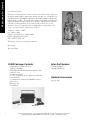
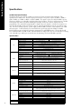
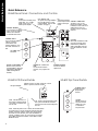
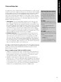
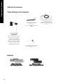
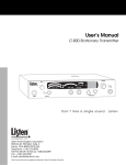
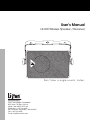
User’s Manual
LR-600 Wireless Speaker / Receiver
Don’t miss a single sound. Listen.
Listen Technologies Corporation
8535 South 700 West, Suite A
Sandy, Utah 84070-2515 USA
Telephone: +1.801.233.8992
Toll Free (North America): 1.800.330.0891
Fax: +1.801.233.8995
E-mail: [email protected]
Welcome to Listen!
Dear Valued Customer,
Thank you for choosing Listen! All of us at Listen are dedicated to providing you
the highest quality products and prompt, efficient customer care. Our products are
manufactured in an ISO-9000 factory that has been independently certified to the
highest quality standards. We stand ready to answer any questions you might have
during installation or in the operation of our products. Should there be any problems with your Listen products, we are ready to help you in any way we can.
Should you have any comments on how we might improve our products or our
service, we’re here to listen. Here’s how to reach us:
Telephone: +1.801.233.8992
Fax: 1.801.233.8995
Toll Free (North America): 1.800.330.0891
E-Mail: [email protected]
Web: www.ListenTech.com
Thank you... and enjoy your listening experience!
Best regards,
The Listen Team
i
LT-800 Package Contents
Listen Part Number
· LR-600 Wireless Speaker / Receiver
(72MHz or 216MHz)
· Adjustable/removable handle/mounting bracket with
leatherette cover
· LA-201 Power Supply
· (2) .18 in (4.5mm) x 1.38 in (35mm) screws with hollow wall anchors
· (1) 16mm nut for mounting the LR-600 on a microphone stand
· Warranty Card
· User Manual
72 MHz: LR-600-072
216 MHz: LR-600-216
Optional Accessories
See page 26-27
Listen™ and the Listen Logo are registered trademarks of Listen Technologies Corporation.
LR-600_2004_08_02 © 2004 Listen Technologies Corporation. All Rights Reserved.
Architectural Specifications . . . . . . . . . . . . . . . . . . . . . . . . . . . . . . . . . . . . . . . . . . .2
Specifications . . . . . . . . . . . . . . . . . . . . . . . . . . . . . . . . . . . . . . . . . . . . . . . . . . . . . . .2
Block Diagram . . . . . . . . . . . . . . . . . . . . . . . . . . . . . . . . . . . . . . . . . . . . . . . . . . . . . .3
Quick Reference . . . . . . . . . . . . . . . . . . . . . . . . . . . . . . . . . . . . . . . . . . . . . . . . . . . .4
Powering Instructions . . . . . . . . . . . . . . . . . . . . . . . . . . . . . . . . . . . . . . . . . . . . . . . .5
Internal Batteries . . . . . . . . . . . . . . . . . . . . . . . . . . . . . . . . . . . . . . . . . . . . . . . . . . . .6
Antenna Options . . . . . . . . . . . . . . . . . . . . . . . . . . . . . . . . . . . . . . . . . . . . . . . . . . .8
Setup & Programming . . . . . . . . . . . . . . . . . . . . . . . . . . . . . . . . . . . . . . . . . . . . . . . .9
Squelch Adjustment . . . . . . . . . . . . . . . . . . . . . . . . . . . . . . . . . . . . . . . . . . . . . . . .11
External Speaker . . . . . . . . . . . . . . . . . . . . . . . . . . . . . . . . . . . . . . . . . . . . . . . . . . .12
Auxiliary Input and Output . . . . . . . . . . . . . . . . . . . . . . . . . . . . . . . . . . . . . . . . . .12
Operation . . . . . . . . . . . . . . . . . . . . . . . . . . . . . . . . . . . . . . . . . . . . . . . . . . . . . . . . .13
Battery Options . . . . . . . . . . . . . . . . . . . . . . . . . . . . . . . . . . . . . . . . . . . . . . . . . . . .14
Mounting & Carrying Options . . . . . . . . . . . . . . . . . . . . . . . . . . . . . . . . . . . . . . . .15
RF Reception Maximization Strategies . . . . . . . . . . . . . . . . . . . . . . . . . . . . . . . . .17
Listen SQ™ . . . . . . . . . . . . . . . . . . . . . . . . . . . . . . . . . . . . . . . . . . . . . . . . . . . . . . .18
Coaxial Cable . . . . . . . . . . . . . . . . . . . . . . . . . . . . . . . . . . . . . . . . . . . . . . . . . . . . .18
Channel Selection . . . . . . . . . . . . . . . . . . . . . . . . . . . . . . . . . . . . . . . . . . . . . . . . . .19
72 MHz Frequency Compatibility Table . . . . . . . . . . . . . . . . . . . . . . . . . . . . . . . . .20
216 MHz Frequency Compatibility Table . . . . . . . . . . . . . . . . . . . . . . . . . . . . . . . .21
Troubleshooting . . . . . . . . . . . . . . . . . . . . . . . . . . . . . . . . . . . . . . . . . . . . . . . . . . . .22
FCC Statement . . . . . . . . . . . . . . . . . . . . . . . . . . . . . . . . . . . . . . . . . . . . . . . . . . . .24
Warranty . . . . . . . . . . . . . . . . . . . . . . . . . . . . . . . . . . . . . . . . . . . . . . . . . . . . . . . . .25
Optional Accessories . . . . . . . . . . . . . . . . . . . . . . . . . . . . . . . . . . . . . . . . . . . . . . . .26
Table of Contents
Table of Contents
Specifications
Specifications
Architectural Specifications
The FM speaker/receiver shall be capable of receiving on 57 wide and narrow band channels. The
speaker/receiver shall be have 10 watts output power and have a frequency response of 50Hz to 15KHz, ±
3dB at 72MHz, or of 50Hz to 10kHz, ± 3dB at 216MHz. The signal to noise ratio shall be 80dB or greater.
The device shall have an adjustable squelch and three-band equalizer. The device will incorporate a backlit
LCD Display that indicates channel and RF signal strength, as well as be used for channel selection
programming. The unit shall be programmable to display only used channels. It shall also incorporate an
electronically lockable volume and channel controls. Controls should be found on the top and rear of the
unit. The device shall incorporate a power supply (120VAC, 60Hz, 43 Watts), with output DC 12V 2500
mA tip negative. It will alternately use an internal battery pack using eight AA alkaline or NiMH
Rechargeable batteries and include recharging components for said NiMH batteries. The speaker should
have a minimum SPL of 110dB (±3dB). An included bracket will be able to be used as a handle for carrying,
or be adjustable up to 360 degrees around the unit for mounting. The Listen LR-600 is specified.
Specifications
Specification
RF Frequency Range
Number of Channels
RF
LR-600-072
LR-600-216
72.025 - 75.950 MHz
216.025 - 216.975 MHz
57 (17 wide, 40 narrow)
57 (19 wide, 38 narrow)
Sensitivity
.6uV typical, 1 uV maximum for 12dB SINAD
Frequency Accuracy
± .005% stability -10° to 40° C (14° to 104° F)
Internal
Antenna
Several available. See www.ListenTech.com for details
Optional Antennas
BNC
External Antenna Connector
Programmable in 20 steps
Squelch
FCC Part 15, Industry Canada
Compliance
** All system specifications are wireless end-to-end
System Frequency Response
System Signal to Noise Ratio
(A-weighted)
System Distortion
Audio
Equalizer
Unbalanced Auxiliary Input
Unbalanced Output
Internal/External Speaker Output
Set-up Controls, Back Panel
User Controls, Top Panel
Controls
User Controls, Back Panel
Programming
Indicators
LCD Display
Volume UP/DOWN, Channel UP (lockable)
Power/Charging, channel UP/DOWN, SEEK (channel, SEEK and volume are lockable)
Unit can be programmed so that only desired channels are displayed. Squelch can
be adjusted for sensitivity. Channel and volume can be locked.
Backlit, indicates channel, RF signal strength, lock status, programming
In-line power supply, Listen part number LA-201
Compliance
Optional Battery Charging
Battery Life (Listen batteries)
Dimensions
(with bracket/handle in up position)
2
15/10 Watts (peak/RMS) continuous power with 4 Ohm load
Internal/External Antenna, Alkaline/NiMH Batteries, SQ Enabled/Disabled
120VAC, 60 Hz, 19 Watts (maximum continuous)
Optional Battery
Environmental
Two phono connectors, unbalanced, 0dBu nominal output level,
+11dBu maximum, impedance 1k Ohms
Power Supply Input
Power Supply Connector
Physical
Two phono connectors, unbalanced, -10dBu nominal input level adjustable,
+11dBu maximum, impedance 100k Ohms
Power Supply Type
Power Supply Output
Power
72MHz: 50Hz - 15kHz (± 3dB)
216MHz: 63Hz - 10kHz (± 3dB)
SQ enabled: 80dB;
SQ enabled: 80dB;
SQ disabled 60dB at 72 MHz
SQ disabled 50dB at 216 MHz
<2% total harmonic distortion (THD) at 80% deviation
Three band, continuously adjustable via rear panel trim pots.
Dimensions (without bracket/handle)
Unit Weight
Unit Weight with LA-201 Power Supply
Unit Weight with eight AA batteries
Shipping Weight
Micophone Stand Mounting Nut
Temperature - Operation
Temperature - Storage
Humidity
15VAC, 1A
.02 in OD x .01 in ID (5.0mm x 2.5 mm), barrel type
UL Listed
Eight AA batteries, alkaline or NiMH.
Fully automatic, 14 hours
12+ hours alkaline (LA-361), 10+ hours NiMH rechargeable (LA-362), mid volume,
music programming (volume and audio type will effect battery life)
11.0 in x 9.0 in x 7.0 in WxDxH (27.9cm x 22.9cm x 17.8cm)
Handle stands off unit 2.0 in (5.1cm)
9.0 in x 7.0 in x 7.0 in WxDxH (22.9cm x 17.8cm x 17.8cm)
6.2 lbs (2.8kg)
7.6 lbs (3.5kg)
6.8 lbs (3.1kg)
10 lbs (2.8kg)
16mm
-10° to +40°C (14° to 104° F)
-20° to +50°C (-4° to 122° F)
0 to 95% relative humidity, non-condensing
Block Diagram
LR-600 Block Diagram
Power
Off/Charge/On
Up
Channel
115VAC
External
Power Supply
18VAC UL
+12VDC or
Listed
8VAC
Down
Seek
Listen LCD Display
(backlighted)
Power Supply
CPU Module
ALK
Battery
Select
Top of Speaker
NiMH
Select
(8) AA Batteries
Alkaline or NiMH
Up
Volume
Terminals
External
Speakers
Down
BNC
Tweeter
External
Digital Pot
Receiver
RF Board
EQ
SQ
Crossover
Network
Speakers
Internal
15/10 Watt
(peak/RMS)
Power Amp
Antenna
Mid Range
SQ On/Off
Low
Mid
High
Phono
Auxiliary
Output
Phono
Auxiliary
Input
3
Quick Reference
Quick Reference
LR-600 Rear Panel: Connections and Controls
POWER
Connect the (included) power
supply here, or a +12VDC
power source such as a
vehicle power adapter.
ON / CHARGE / OFF
To operate and charge batteries,
move to ON position. To only
charge batteries, move to CHG
position. See page 7.
EXTERNAL ANTENNA
If you need more receiving
range, connect an external
antenna here. Antennas
are available from Listen.
ANTENNA SELECT
If you connect an external
antenna, move this
switch to EXT. If no
external antenna is used,
the switch should be on
INT.
LCD PANEL
See below
EQ
Three-band equalizer
used to adjust sound AUXILIARY CONNECTORS
quality to meet your To listen to a CD, TV, etc
through the speaker, connect
needs.
to AUX IN; to route audio to an
external device such as a
recorder or mixer, connect to
AUX OUT.
EQ
SQ MODE
When ON, activates the Listen
SQ mode, improving noise
performance by better than
20dB. Transmitter must also
have SQ enabled to use this
mode.
Channel
Select
UP
Volume
DOWN
CHANNEL UP / DOWN and
SEEK
Use to select and search
channels, or to program the
unit.
BATTERY COMPARTMENT
Remove access panel to
change batteries. Unit holds
eight optional AA batteries
(NiMH rechargeable or
alkaline).
EXTERNAL SPEAKER
Connect an external
speaker here.
LR-600 Top Panel Details
LR-600 LCD Panel Details
RF Signal Strength
Indicates channel, or when volume up or down
button is pressed, indicates volume.
CHANNEL SELECT
Selects the next
programmed
channel.
Channel
Select
PGM - indicates the unit is in
the program mode that allows
you to lock out channels that
are not used.
L/O - When in the programming mode,
this symbol indicates the channel is
locked out and will not be displayed to
the user.
LOCK - When the padlock icon is visible, the channel buttons
are locked and you cannot change the channel. When the
padlock is flashing, both the channel and volume buttons
are locked. To lock channels, press and hold SEEK for 5
seconds. Repeat to unlock. To lock channels and volume,
press SEEK and then the UP button. Press SEEK and then
DOWN to unlock.
4
UP
Volume
DOWN
VOLUME
Adjusts volume up
and down.Volume
setting of 0 to 26
is indicated on
rear panel LCD.
Powering
LR-600 Powering Instructions
There are three options for powering your LR-600:
· Supplied power supply
· External +12VDC Battery or Power Supply
· Internal Batteries
Power Supply (included with unit)
If you are using the LR-600 with the external power supply, connect the power supply to the LR-600
and plug the power supply into a 115VAC/60 Hz outlet.
External +12VDC Source
If you are using the LR-600 with an external +12VDC battery or power supply, obtain a power
connector with following dimensions:
0.098 in (2.5 mm) inside diameter
0.217 in (5.5 mm) outside diameter
0.374 in (9.5 mm) length
Wire the connector so the tip is positive. Connect to a 12VDC battery or +12VDC output of a
power supply.
5
Internal Batteries
LR-600 Internal Batteries
Internal Batteries
If you are using the LR-600 with internal batteries, do the following:
·
·
·
·
Open the battery compartment by removing the thumbscrew and then removing the cover.
Slide the battery holder out of the battery compartment.
Install eight AA alkaline or NiMH batteries with polarity noted on the battery holder.
Replace the battery holder and secure the battery compartment cover.
IMPORTANT: Slide the battery switch to the alkaline or NiMH battery position depending on the
battery type you are using.
Place the Battery switch in the ALK
position if you are using alkaline
batteries.
Place the Battery switch in the NiMH
position if you are using rechargeable
NiMH batteries.
IMPORTANT: You must place the Battery switch in the appropriate position for the type of
batteries you will be using. If you are using alkaline batteries and the switch is in the NiMH
position, the unit will attempt to charge the batteries when connected to a power supply or
external battery. Attempting to charge alkaline batteries can result in permanent damage
to the unit, and the batteries may explode.
6
Internal Batteries
LR-600 Internal Batteries continued
For NiMH battery operation, you must charge the batteries for 13 hours before use. To charge the
batteries, plug the unit into the power supply or external +12VDC supply and move the power
switch to either CHG or ON. The batteries will charge in either position.
In Charge mode, the battery symbol
will cycle between low, mid and full.
Powering the unit ON
Turn the unit on by sliding the power switch to the ON position. The LCD will activate; if using the
LR-600 on the power supply, the LCD backlight will activate and remain on. If you are using the
unit on batteries, the LCD backlight will operate for 12 seconds after any button is pressed, and then
dim to conserve battery life.
7
Antenna Options
LR-600 Antenna Options
The LR-600 has two antenna options: internal or external. To use the internal antenna, move the
antenna switch to INT. To use the external antenna, move the switch to EXT.
Internal antenna
As shipped, your LR-600 is set up for use with its internal antenna. The
internal antenna will work well for a large number of uses, but it cannot be
positioned for best coverage. When using the LR-600’s internal antenna,
make sure the antenna switch is in the INT position. If your receive signal
is noisy or weak, you may need to use an external antenna.
External antenna
There are three options for the external antenna:
Quarter wave helical antenna
This antenna mounts directly to the back of the LR-600. Order
these part numbers from Listen:
· LA-123 (72 mHz)
· LA-124 (216 mHz)
Remote antenna
See page 17, RF Reception Maximization Strategies. With a remote
antenna, you’ll be able to get the best reception by strategically placing
the antenna.
Antenna options available from Listen:
· LA-122 Universal Antenna Kit (72 and 216 mHz)
· LA-123/LA-124 (72/216 mHz) to be mounted remotely
· LA-107 Ground plane antenna (216 mHz).
Wire antenna
You can build a wire antenna by soldering a wire to the center conductor on
a BNC connector. Recommended lengths for wire antennas:
· 72 mHz: 39 in (1 m)
· 216MHz: 13 in (0.32 m)
8
Setup & Programming
LR-600 Setup and Programming
Channel Selection
Using the channel select buttons (UP and DOWN buttons on the rear panel) or the SEEK button,
select the desired receive channel. For more information, see Channel Selection on page 19.
Use Channel UP / DOWN or Seek to
select a receive channel.
Locking Channel Selection
If you don’t want the user to have the ability to change the channel, it is highly recommended that
you lock the channel select function. This is accomplished as follows:
· Press and hold the SEEK button for 5 seconds.
· The padlock icon will appear in the display.
· To unlock the channel selection function, press and hold the SEEK button until the
padlock icon goes out.
A padlock in the display means the channel
is locked and a new channel cannot be
selected. If the padlock icon is flashing, both
the channel and volume settings are locked
(see below).
Locking Both Volume and Channel Selection
Once the channel and desired volume have been set, you can lock both functions as follows:
· Press the SEEK button and then the UP button on the rear panel.
· The PADLOCK icon will flash.
· To unlock both the volume and the channel selection function press the SEEK button and then
the DOWN button on the rear panel.
Setting the SQ
Press Seek, and then the Channel UP button to lock volume and channel.
Press Seek, then DOWN to unlock.
9
Setup & Programming
LR-600 Setup and Programming continued
Setting the SQ Switch
For more information on SQ, see Listen SQTM on page 18.
The SQ function improves the noise performance of the LR-600 by at least 20dB. To use this
function, the transmitter must also be a Listen brand transmitter with SQ.
To use the SQ function, do the following:
· Verify the transmitter has SQ and the SQ function is turned on.
· Move the SQ switch on the back of the unit to the ON position.
· If you are using the LR-600 with another brand transmitter or if you don’t want to use the SQ
function, move the SQ switch to the OFF position.
To use Listen SQTM, slide the switch to
the ON position. Your transmitter’s SQ
function must also be on.
Programming the Channel Select Button
The channel select button on the top of the unit is designed to give users the ability to choose
between different channels. If you don’t want to give users this function, it is recommended that
you lock this feature as described on page 9.
If you want to use this function, you must program the unit for the channels you are using. For
example, you are using 72 MHz channels A, E and I. You would only want the LR-600 to receive
on channels A, E, and I. When the Channel Select button has been programmed, the
unit will select A the first time the user presses the button; when the user presses the button successively, E will be selected, then I, then A again.
Note: The UP button on the rear panel and Channel Select button on the top of the unit perform the same function for end users. To program the unit so that it only receives on certain
channels, do the following:
·
·
·
·
·
·
Press the UP and DOWN buttons together and release. The PGM icon is displayed.
Press the UP or DOWN button to select channels.
When you get to a channel that you don’t want displayed, press the SEEK button.
The L/O icon will be displayed indicating the channel is locked out and will not be displayed.
Repeat for all channels that you want locked out.
When done, don’t press a button for 10 seconds and the unit will return to normal operation.
In the example above, only three channels are used. Therefore, you will need to lock out 54
channels from use.
Press the Channel UP and DOWN buttons at the same
time to enter Program mode (shown by the PGM icon).
While in Program mode, press SEEK to lock out a channel
that you do not want available to the end user. L/O will
show on the display.
10
Squelch Adjustment
LR-600 Squelch Adjustment
When the transmitter is not turned on, the squelch function mutes the audio so that random noise is
not heard through the speaker.
The squelch function can be programmed for more or less sensitivity. When the squelch function is
programmed for more sensitivity, you sacrifice transmission range in exchange for more reliability of
the squelch function. When the squelch function is programmed for less sensitivity, you achieve
greater transmission range in exchange for less reliability of the squelch function. This means that
even if the transmitter is off, you may hear noise in the speaker. You can try different squelch settings
for your application.
Examples for setting the squelch sensitivity high
· You absolutely don’t want the unit to have noise when the transmitter is off.
· The transmitter is close to the LR-600.
Examples for setting the squelch sensitivity low
· It doesn’t matter if the user hears the noise if the transmitter is turned off.
· The transmitter is located a long distance from the LR-600.
The adjustable squelch can be programmed from 0 (no squelch) to a maximum of 20 (highest
sensitivity). The default setting is 3.
To program the squelch setting, do the following
·
·
·
·
·
·
Turn the unit off.
Press and hold the SEEK button.
Turn the unit on.
Release the SEEK button.
The squelch setting is shown on the display. Default is 3.
Use the UP and DOWN buttons on the rear panel to select the setting you want. Note the RF
meter still operates, giving you relative RF power from the transmitter.
· When you are done, press SEEK to store the new squelch setting.
While in Squelch programming
mode, channel UP / DOWN
buttons are used to change
squelch sensitivity. 03 is the
factory default.
Use Seek to enter Squelch
programming mode and to save
settings (see instructions above).
11
External Speaker & Auxiliary
LR-600 External Speaker
You can connect an external speaker to the LR-600. Make sure that the speaker is 4 Ohms or
greater. The Listen LA-316 speaker provides the same look as the LR-600.
An external speaker (4 Ohms or
greater) may be connected to the
speaker terminals below the LCD
panel.
LR-600 Auxiliary Input and Output
Additional audio can be mixed with the receive audio from the transmitter. To accomplish this,
use the Auxiliary Input connectors. Simply take the audio output of your device (such as a CD
player, TV or computer) and connect it to the two phono connectors on the rear panel of the
LR-600.
If you want to take the audio out of the LR-600 and record it or send it to a mixer, use the
Auxiliary Output phono connectors to connect to your recorder or mixer.
12
Operation
LR-600 Operation
To turn the unit on, move the power switch to the ON position.
LCD Display
Once the unit is on, the LCD display will illuminate. Notice that when the unit is in operation
on the power supply, the LCD backlight will remain lit continuously. When on battery power,
the backlight will remain lit for 10 seconds after any button is pushed. This is designed to save
battery life.
Signal Strength
Padlock Icon
Channel or Volume
Battery
Channel/Volume Control
When the volume control is pushed, the number indicates the volume setting between 0 and 26.
Otherwise the channel is shown. The channel should be the same as the transmitter.
Battery
The battery icon shows the amount of battery life remaining in full, ½, ¼ and flashing
increments (indicating low battery). When charging, the battery icon changes through all of
these states to show it is charging.
Signal Strength
Just as on your cellular telephone, the dots above the Listen logo show the signal strength
coming from the transmitter.
Padlock Icon
If illuminated, indicates the channel selection function is locked. If flashing, indicates the
channel selection and volume control functions are locked. See page 12 for more information.
13
Operation
LR-600 Operation
Battery Operation
To set up the unit for battery operation, see page 8.
To operate the unit on batteries, move the Power switch to the ON position.
Alkaline battery operation. Note
that the power supply is not
connected and the Battery
switch is in the ALK position.
To charge the optional rechargeable batteries, connect the unit to the power supply or an external battery, then place the power switch in the ON or CHG position. DO NOT ATTEMPT TO
CHARGE ALKALINE BATTERIES.
Charging mode. Note that
rechargeable NiMH batteries are
installed and the Battery switch is
in the NiMH position. The battery
icon cycles through low, mid and
high level displays to indicate
charging.
IMPORTANT: You must place the Battery switch in the appropriate position for the
type of batteries you will be using. If you are using alkaline batteries and the
switch is in the NiMH position, the unit will attempt to charge the batteries when
connected to a power supply or external battery.
Attempting to charge alkaline batteries can result in permanent damage to the
unit, and the batteries may explode.
It takes 13 hours to fully charge the batteries. When the batteries are charging, the battery icon
changes from ¼ to ½ to full and then repeats to indicate charging.
When not using the unit, it is advisable to leave the unit connected to the power supply to keep
the batteries fully charged. This will not damage the batteries.
When the batteries are fully charged, the unit will automatically shut off. To reactivate the unit,
turn the unit OFF and then back ON.
During battery operation, if the battery icon begins flashing on the Low level (one bar showing),
your batteries are almost exhausted and shutdown is imminent. Connect to a power supply or
replace the batteries.
14
Operation & Mounting
LR-600 Operation
Volume Adjustment
Adjust the volume setting for a comfortable level by pressing the VOLUME UP and
DOWN buttons on the top of the unit. The volume setting (a number between 0 and
26) will be shown on the display.
To lock the volume setting see page 9.
Equalization Adjustment
The purpose of the equalizer is to adjust the sound quality to your specific needs and
taste. Use a small screwdriver to adjust the LOW, MID and HI positions. These
correspond to the following center frequencies: 250 Hz, 1 kHz and 4 kHz.
Adjust to the center position to make the frequency response flat.
Channel Selection
To select a program channel, press the CHANNEL SELECT button on the top of the unit. To
program this function see page 14. If channels have not been programmed, the unit will step through
all available channels as you repeatedly press the CHANNEL SELECT button. If channels have
been programmed, you may wish to use the Seek button on the rear panel instead. Pressing Seek will
cause the LR-600 to search for an available transmission. You may also use the Channel UP and
DOWN buttons on the rear panel to step through the channels available to the LR-600.
Receive channels may be found using the CHANNEL
SELECT button on top of the unit, the Seek button on
the rear panel, or the Channel UP / DOWN buttons
on the rear panel.
LR-600 Mounting / Carrying Options
The U bracket that comes standard with the LR-600 can be used to permanently
mount the unit, set the unit at an angle on a desktop, or be used as a carrying handle.
To change the position of the U bracket, do the following:
· Loosen the two screws (the large knobs) on both sides of the LR-600.
Note that you have to loosen the screws considerably to allow the bracket to
swivel. This is because the bracket is keyed to prevent slipping when in use.
· Rotate the bracket to the desired position.
· Retighten the two screws.
The knobs on either side of the unit
must be loosened considerably in
order to swivel the U bracket to a
different position.
15
Mounting
LR-600 Mounting Options
You have the option to mount the LR-600 on a microphone stand, or you can
mount the U bracket directly to any vertical or horizontal surface.
Microphone Stand Mounting
· Locate the microphone stand nut in the included poly bag, or use the nut
that comes with the microphone stand.
· Remove the leatherette handle cover.
· Position the U bracket so that it will hold the LR-600 upright on the
microphone stand.
· Screw the nut onto the stand and tighten with a wrench.
Vertical / Horizontal Permanent Mounting
· Remove the U bracket by loosening the two screws on both sides of the
LR-600. Be careful not to lose the washers.
· Using the two self-tapping screws and (if necessary) hollow wall anchors,
mount the bracket to any surface.
· Position the LR-600 into the bracket and tighten the two screws.
16
Maximizing RF Reception
Maximizing RF Reception Strategies
For proper and dependable operation, the LR-600 should receive a strong and consistent signal from the originating transmitter. The following strategies should be
used to maximize this signal:
a. When designing and installing your system, keep in mind that the location of
both the transmitting and receiving antennas is critical to maximizing signal
strength.
b. Eliminate or minimize obstructions between the transmitting antenna and the
receiving antenna.
c. Minimize the distance between the transmitting and receiving antennas.
d. Move transmitting and receiving antennas away from metal objects.
e. Consider using a remote antenna instead of the internal antenna. This will
allow you to place the antenna at a location with improved line of sight to the
transmitting antenna. (You will need to be careful about the type and length of
coaxial cable; see the note above.)
f. Place the transmitting antenna as high as possible.
g. Orient both transmitting and receiving antennas vertically.
h. Consider using a gain antenna such as a Yagi type antenna (216 MHz only).
CAUTION: When installing antennas, ensure the antenna is clear of power lines.
NOTES: If the RF signal to the LR-600 is too high, the audio will be distorted.
This may happen if you are within 40 feet of the LT-800 transmitter. Consider
reducing the output power of the transmitter or optionally removing the antenna
on the LR-600 (there is sufficient internal antenna inside the LR-600 to receive an
adequate signal from the transmitter).
Coaxial cable, connectors, and optional antenna mounting kits are available from
Listen. Visit our website for details.
17
Listen SQ TM & Coaxial Cable
Listen SQ™- Improving Your Listening Experience
We are accustomed to listening to low noise, high fidelity audio (delivered via CD,
DVD, etc.). FM radio systems, such as those made by Listen, have more inherent
noise compared to most sound systems. To reduce noise of our systems, Listen uses
a noise reduction technology called ListenSQ™. Both the transmitter and receiver
must have the SQ feature enabled to achieve the desired results. SQ is available
on new Listen systems, including the system you received in this shipment. If you
are planning to use this product with older Listen systems that do not have Listen
SQ or equipment not manufactured by Listen, you should disable Listen SQ.
Your Listen equipment has been shipped to you with the SQ feature enabled. You
may need to disable the SQ function for one or more of the following reasons:
SQ Summary
· Improves noise performance by at least 20dB
· SQ is NOT compatible
with older version Listen
products
· SQ is NOT compatible
with other manufacturers’
products
· SQ is NOT squelch
1.
You are using your new Listen system with older version Listen equipment that
does not have the SQ function.
2.
You are using your new Listen system with equipment supplied by other manufacturers.
3.
You expect that end users may bring and use their own receivers that don’t
have the SQ function.
Coaxial Cable
The antenna for the LR-600 can be mounted directly on the unit if desired.
However, you may find that the unit will provide better performance when the
antenna is located elsewhere. If you plan to mount the antenna in a different location than on the top of the unit, you must use cable and connectors rated at 50
Ohms. Although cable used for cable TV installations looks similar to this cable, it
won’t work with your Listen system.
If you need to run cable over a greater length than 50 feet for 216MHz applications
or greater than 100 feet for 72MHz applications, we recommend that you use RG-8
cable rather than RG-58. It is a lower loss cable, meaning that more of your signal
will reach the antenna.
Long cable runs can result in signal degradation due to “loss” characteristics of the
cable. At 72MHz, there is an average loss of 2dB per 100 feet of cable and at
216MHz an average* loss of 5 dB per 100 feet of cable. (A 3dB loss means half of
your power has been lost.) However, it is better to suffer coaxial power loss than to
try to shoot your signal through obstacles! Obstacles, especially metal, can create
drop-outs or reflections of your signal that will result in poor listening conditions.
*NOTE: There are many varieties of 50 Ohm, RG58 and RG8 cables. You may
purchase a cable that is better or worse than this value. Please check with the
cable vendor or manufacturer for exact specifications.
18
· To work properly, SQ
must be enabled for both
the transmitter and
receivers
· SQ can be disabled to permit operation with older
Listen products or other
manufacturers’ products
Channel Selection
Channel Selection
It is important to choose channels that are free from interference to achieve proper
operation of your Listen equipment. This process is trial and error. Before turning
on the transmitter, listen to the wide band channels (lettered channels at 72MHz
and channels that start with a “2” for 216MHz when using a Listen receiver).
Listen to the audio through the headphone or via the speaker. Choose a channel
with the least amount of interface. Unless you are interfacing with an existing narrowband transmission system, always use a wide band channel. If you are using
multiple channels follow this process:
a. Same Space If you are using multiple transmitters in the same space, the
most number of channels that will work simultaneously is six at 72MHz and
three at 216MHz. With all of the transmitters off, listen for interference on all
the wide band channels via the headphone jack on a Listen receiver. Using the
frequency compatibility tables on pages 12-13, eliminate any channels that have
noticeable interference. Now choose the channels with the widest channel
spacing. It is recommended that adjacent channels be spaced at least 300KHz.
If there is no interference the following channels are recommended: A, C, E, I, J,
and H for 72MHz and channels 2A, 2K and 2V at 216MHz.
b. Distributed Spacing If you are using transmitters that are spread out over
space, you can achieve more simultaneous broadcast channels. However, it is
critical that your receiver(s) be located as close to its transmitter as possible.
You can use adjacent channels (see frequency compatibility tables on pages 1213) in this case as long as the adjacent channel transmitter is at least 50% further away from the receiver as its transmitter. Example: The transmitter for the
receiver on channel E is 100 feet from the receiver. The adjacent channel transmitter on channel D should be at least 150 feet away.
Wide Band Recommendation
Listen recommends that you always use
a wide band channel unless you need to
be compatible with existing narrow
band receivers from other manufacturers. Wide band channels have lower
noise than their narrow band counterparts.
At 72MHz
The LT-800 at 72MHz operates on 17
wide band channels and 40 narrow band
channels.
· Letters= Wide Band Channels
(Example: E)
· Numbers= Narrow Band Channels
(Example: 32)
At 216MHz
The LT-800 at 216MHz operates on 19
wide band channels and 38 narrow band
channels.
· “2” as left digit= Wide Band
·
Channel
(Example: 2C)
“1” and “3” as left digits= Narrow
Band Channels (Examples: 1A; 3R)
It is highly recommended that after channel selection has been achieved, you lock
the channel so that it cannot be changed by the user. To accomplish LOCK on the
LT-800, press both the UP and DOWN buttons simultaneously for 5 seconds.
Repeat the process to unlock.
Notes in regard to using 72MHz and 216MHz systems:
i. 72MHz in a secondary frequency band. This means that other transmitters are
licensed to use these frequencies. Thus, you may experience interference from
paging transmitters and other types of transmissions. You will need to find a
clear channel by listening to all the wide band channels.
ii. 216MHz is a primary frequency band and no other types of transmissions are
authorized to use it. Thus, you will find the highest probability of clear channels
in this band. However, you may experience intermodulation of the TV Channel
13 aural carrier if there is a channel 13 transmitter in your area and you are close
to the transmitter. If you cannot find a clear channel in 216MHz band due to
channel 13, it is recommended that you switch to a 72MHz system.
19
72MHz Compatibility
72MHz Compatibility Chart
Frequency
MHz
20
72.0250
72.0500
72.0750
72.1000
72.1250
72.1500
72.1750
72.2000
72.2250
72.2500
72.2750
72.3000
72.3250
72.3500
72.3750
72.4000
72.4250
72.4500
72.4750
72.5000
72.5250
72.5500
72.5750
72.6000
72.6250
72.6500
72.6750
72.7000
72.7250
72.7500
72.7750
72.8000
72.8250
72.8500
72.8750
72.9000
72.9250
72.9500
72.9750
74.6250
74.6500
74.6750
74.7000
74.7250
74.7500
74.7750
75.2250
75.2500
75.2750
75.3000
75.3250
75.3500
75.3750
75.4000
75.4250
75.4500
75.4750
75.5000
75.5250
75.5500
75.5750
75.6000
75.6250
75.6500
75.6750
75.7000
75.7250
75.7500
75.7750
75.8000
75.8250
75.8500
75.8750
75.9000
75.9250
75.9500
75.9750
Listen
Phonic
Ear
Comtek
Phonak
Williams*
1
1
1
A1
2
A
3
2
A
3
2
A
3
A2
A
A3
4
K
5
4
K
5
4
K
5
A4
K
K5
6
B
7
6
B
7
6
B
7
K6
B
B7
8
N
9
8
N
9
8
N
9
B8
N
N9
10
C
11
10
C
11
10
C
11
N0
C
C1
12
O
13
12
O
13
12
O
13
C2
O
O2
14
D
15
14
D
15
14
D
15
4
D
D5
16
P
17
16
P
17
16
P
17
D6
P
P7
18
E
19
18
E
19
18
E
19
P8
E
E9
20
33
20
33
20
33
E0
E3
34
I
35
34
I
35
34
I
35
E4
I
I5
36
37
36
37
36
37
I6
I7
38
J
39
38
J
39
38
J
39
I8
J
J9
40
R
21
40
R
21
40
R
21
J0
R
R1
22
F
23
22
F
23
22
F
23
R2
F
F3
24
S
25
24
S
25
24
S
25
F4
S
S5
26
G
27
26
G
27
26
G
27
S6
G
G7
28
T
29
28
T
29
28
T
29
G8
T
T9
30
H
31
30
H
31
30
H
31
T0
H
H1
(11, 1)
(2)
(12, 3)
A, (13, 4)
(14, 5)
(6)
(15, 7)
K, (8)
(16, 9)
(10)
(17, 11)
B, (18, 12)
(19, 13)
(14)
(20, 15)
N, (16)
(21, 17)
(18)
(22, 19)
C, (23, 20)
(24, 21)
(22)
(25, 33)
O, (24)
(26, 25)
(26)
(27)
D, (28)
(29)
(30)
(30, 31)
P, (32)
(31, 33)
(34)
(32, 35)
E, (33, 36)
(34, 37)
(38)
(35, 39)
(36, 40)
(41)
(37, 42)
I, (38, 43)
(39, 44)
(45)
(40, 46)
(41, 47)
(48)
(42, 49)
J, (43, 50)
(55, 51)
(52)
(45, 53)
R, (54)
(46, 55)
(56)
(47, 57)
F, (48, 58)
(49, 59)
(60)
(50, 61)
S, (62)
(51, 63)
(64)
(52, 65)
G, (53, 66)
(54, 67)
(68)
(55, 69)
T, (70)
(56, 71)
(72)
(57, 73)
H, (58, 74)
(59, 75)
(76)
(60, 77)
32
32
32
H2
Gentner
Telex
Drake
A
72.1
B
72.2
C
72.3
D
72.4
E
72.5
F
72.6
G
72.7
H
72.8
I
72.9
1
2
3
4
5
6
7
8
9
10
11
12
13
14
15
16
17
18
19
20
21
O
22
23
24
P
25
26
Q
27
28
J
75.5
K
75.6
L
75.7
M
75.8
N
75.9
29
30
31
32
33
34
35
36
37
*Parenthesis indicate T35 and T20 narrowband.
NOTE: Wideband frequencies in highlighted rows.
216MHz Compatibility Chart
216MHz Compatibility Chart
Frequency
MHz
Listen
216.0125
216.0250
216.0375
216.0625
216.0750
216.0875
216.1125
216.1250
216.1375
216.1625
216.1750
216.1875
216.2125
216.2250
216.2375
216.2625
216.2750
216.2875
216.3125
216.3250
216.3375
216.3625
216.3750
216.3875
1A
2A
3A
1B
2B
3B
1C
2C
3C
1D
2D
3D
1E
2E
3E
1F
2F
3F
1G
2G
3G
1H
2H
3H
216.4125
216.4250
216.4375
216.5125
216.5250
216.5375
216.5625
216.5750
216.5875
216.6125
216.6250
216.6375
216.6625
216.6750
216.6875
216.7125
216.7250
216.7375
216.7625
216.7750
216.7875
216.8125
216.8250
216.8375
216.8625
216.8750
216.8875
216.9125
216.9250
216.9375
216.9625
216.9750
216.9875
1J
2J
3J
1K
2K
3K
1L
2L
3L
1M
2M
3M
1N
2N
3N
1P
2P
3P
1R
2R
3R
1S
2S
3S
1T
2T
3T
1U
2U
3U
1V
2V
3V
Phonic
Ear
41
42
43
44
45
46
47
48
49
51
52
53
54
55
56
57
58
59
60
Comtek
Phonak
1
41
2
3
42
4
5
43
6
7
44
8
9
45
10
11
46
12
13
47
14
15
48
16
1
41
2
21
42
4
5
43
22
23
44
8
9
45
24
25
46
12
13
47
26
27
48
16
17
49
18
21
51
22
23
52
24
25
53
26
27
54
28
29
55
30
31
56
32
33
57
34
35
58
36
37
59
38
39
60
40
17
49
18
61
29
62
28
52
64
65
53
81
82
54
68
69
55
83
84
56
72
73
57
76
85
58
86
77
59
88
79
60
80
Williams Gentner
NOTE: Wideband frequencies in highlighted rows.
CSI
1
1
2
10
A
3
6
B
4
14
C
5
2
D
6
11
AVR
Light
Speed
C01
N01
C05
E
7
7
F
8
15
C09
N09
C12
N12
C18
N18
C21
G
9
18
H
10
3
I
11
12
C24
C25
J
12
8
K
13
16
L
14
19
15
4
N64
C29
C32
C33
N72
C37
N77
13
9
17
C39
5
C40
N80
21
Troubleshooting
LR-600 Troubleshooting
The unit does not power up, or it has stopped operating.
· Ensure the power supply is connected properly.
· Your batteries may be dead. Replace or recharge the batteries.
The audio is muted occasionally.
· The unit’s squelch sensitivity (a smaller number in the squelch setting) may
be too high. Either improve the RF signal path (a remote antenna may
help) or adjust the squelch setting for less squelch sensitivity.
I hear noise coming from the receiver.
· You may have inadequate RF signal strength. Adjust the positioning of the
antennas. Make the transmitter is on high power.
· You may be experiencing interference, try a different channel.
· Make sure the transmitter and receiver are on the same channel.
· The squelch sensitivity may be too low. Try setting it higher. See page 15.
The channel is often accidentally changed.
· Lock the unit on channel by pressing and holding the SEEK button for five
seconds. The padlock symbol is illuminated on the LCD.
There is no audio.
· Make sure the transmitter and receiver are on the same channel.
· Make sure the volume is turned up.
· Make sure the squelch adjustment is set correctly.
The audio is distorted.
· Make sure the transmitter and receiver are on the same channel.
· Make sure that the SQ switch is ON or OFF for both the transmitter and
receiver.
· Make sure the audio level is not set too high.
· Make sure you are not too close to the transmitter.
The level of my Auxiliary device (CD player, etc.) is low.
· Adjust the output volume at the auxiliary device you are using.
I cannot change channels.
· The unit is locked on channel. Press and hold the SEEK button for five
seconds.
I cannot change the unit’s volume.
· The volume control is locked (the flashing padlock icon indicates this).
Press and hold the SEEK button and then the DOWN button to unlock.
I
·
·
·
cannot pick up the transmitter.
Make sure the antenna switch is in the correct position.
Make sure the transmitter is on and is operating on the same channel.
You may need to use an external remote antenna.
I can see that I am receiving a channel on RF signal meter, but I
cannot hear any audio.
· The adjustable squelch may be set too high. See page 15.
22
Troubleshooting
LR-600 Troubleshooting
When the transmitter is off, I hear noise.
· The adjustable squelch may be set too low. See page 15.
I’m trying to find a channel that does not show up on the display.
· The channel may be “locked” out. See page 12.
Will the unit charge the batteries when the power supply is plugged
into the unit?
· Yes, as long as the power switch is in the ON or CHG position.
Can I use this product in a motor vehicle?
· Yes, the LR-600 is designed to work with +12VDC from any vehicle. See page 7
for more information.
The unit does not sound good.
· Make sure SQ is on or off on both the transmitter and the LR-600.
· Verify the equalizer has been adjusted properly. Set to flat (center position) to
start with. See page 18 for more information.
· Make sure the transmitter and LR-600 are on exactly the same channel.
· Make sure the LR-600 is not too close to the transmitter.
The rechargeable batteries don’t last very long.
· They may need to be replaced if they have been used for over 18 months.
· Make sure the charger stays on for the full 13 hours to fully charge the batteries.
· At high volume levels, the batteries will not last very long.
· Make sure you are using quality, long life NiMH batteries.
I have rechargeable batteries in the unit, but they aren’t recharging.
· Make sure the Battery switch is set to NiMH. The unit will not charge batteries
when the switch is in the ALK position.
The unit won’t work on batteries.
· Make sure you are using charged batteries.
· Check the battery polarity of the batteries in the battery holder.
· Make sure the battery holder connector is secure.
If you are still having problems after checking the above items, call Listen for help.
We are available from 8 AM to 5 PM Mountain time, Monday through Friday, at
1.800.330.0891 or 801.233.8992, or you can e-mail us at [email protected].
23
FCC Statement
FCC Statement
This equipment has been tested and found to comply with the limits for a class B digital device,
pursuant to part 15 of the FCC Rules. These limits are designed to provide reasonable protection
against harmful interference in a residential installation. This equipment generates, uses and can
radiate radio frequency energy and if not installed and used in accordance with the instructions,
may cause harmful interference to radio communications.
However, there is no guarantee that interference will not occur in a particular installation. If
this equipment does cause harmful interference to radio or television reception, which can be
determined by turning the equipment off and on, the user is encouraged to try to correct the
interference by one or more of the following measures:
· Reorient or relocate the receiving antenna.
· Increase the separation between the equipment and receiver.
· Connect the equipment into an outlet on a circuit different from that to which the receiver is
connected.
· Consult the dealer or an experienced radio/TV technician for help.
This equipment has been certified to comply with the limits for a class B computing device,
pursuant to FCC and IC Rules. In order to maintain compliance with FCC and IC regulations,
shielded cables must be used with this equipment. Operation with non-approved equipment or
unshielded cables is likely to result in interference to radio and TV reception. The user is
cautioned that changes and modifications made to the equipment without the approval of the
manufacturer could void the user’s authority to operate this equipment.
24
Warranty
Warranty
Listen Technologies Corporation (Listen®) warrants the LT-800 Stationary Transmitter to be free
from defects in workmanship and material under normal use and conditions for the useful lifetime of
the product from date of purchase. This warranty is only available to the original end purchaser of
the product and cannot be transferred. Warranty is only valid if warranty card has been returned
within 90 days of purchase. This warranty is void if damage occurred because of misuse or if the
product has been repaired or modified by anyone other than a factory authorized service technician.
Warranty does not cover normal wear and tear on the product or any other physical damage unless
the damage was the result of a manufacturing defect. Listen is not liable for consequential damages
due to any failure of equipment to perform as intended. Listen shall bear no responsibility or
obligation with respect to the manner of use of any equipment sold by it. Listen specifically
disclaims and negates any warranty of merchantability or fitness of use of such equipment including,
without limitation, any warranty that the use of such equipment for any purpose will comply with
applicable laws and regulations. The terms of the warranty are governed by the laws of the state of
Utah, USA. Listen will only accept returned products with prepaid shipping and with a return
authorization number. To receive a return authorization number call 1.800.330.0891 or
+1.801.233.8992. Please see www.ListenTech.com or contact Listen for complete warranty details.
25
Optional Accessories
Optional Accessories
Other Stationary Unit Antennas
90 Degree Helical
Coaxial Dipole Antenna
(Rear Mount)
LA-123 for 72MHz or LA-124 for
216MHz
LA-116
LA-122 Universal
Antenna Kit
The single solution for all of your
indoor remote antenna needs.
Includes: 72 and 216MHz
components; flexible and rigid
dipoles and monopole radials;
hardware for multiple mounting
configurations; and 25 feet
(7.6m) of RG58 coax cable.
Ground Plane Antenna
LA-107
Batteries
26
NiMH Rechargeable
AA Batteries (pkg of two)
High Capacity AA
Alkaline Batteries (pkg of two)
LA-362
LA-361
Optional Accessories
Optional Accessories continued
BNC Adapter
LA-121
BNC Connector
for RG58
BNC Connector
for RG8
LA-127
LA-128
RG58 Coaxial
Cable
RG8 Coaxial
Cable
Installation of
BNC Connectors
LA-112
LA-113
LA-114
Expansion Speaker
Expansion Speaker
LA-316
27
28
Notes
Listen Technologies Corporation
8535 South 700 West, Suite A
Sandy, Utah 84070-2515 USA
Telephone: +1.801.233.8992
Toll Free (North America): 1.800.330.0891
Fax: +1.801.233.8995
E-mail: [email protected]