1
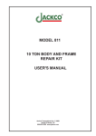
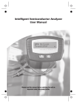
Keyless Entry & PLRB
Control Module User Manual
GUIDE COPY TO REMAIN IN VEHICLE
Complete PLRB
In Enclosure
#6
Component I.D.
#5
J1
MODULE
#1
#7
J3
TOGGLE
3C ON
3C OFF
EXTERNAL
OUTPUT
UNLOCK
LOCK
UNLOCK
FIG 3
#2
#2
Part List:
#1- 6 pin timed relay.
#2- 5 pin 30/40 relays.
#3- 30 amp fuses.
#4- Eight 1/4“ stab connectors.
#5- Power & Ground lugs.
#6- 2 red 2 green LEDs.
#7- RC unit location and
mounting hole.
J1 Module: Keyless Entry Control Module Input.
J3 Toggle: Dip Switch 3rd Channel Flip/Flop Option.
External Output: 3rd Channel Or Additional Piggy
Back Relay Option. Use Provided Jumper And Close
Pins Indicated To Activate 3rd Channel. Slave Piggy
Pack On, Close Pins 3C As Indicated.
1
www.poplocks.com
HDC Inc.
Keyless Entry & PLRB-RC3
Troubleshooting
TROUBLE SHOOTING PLRB-RC3 & POWER LOCK SYSTEM
2
Problem
Solution
1. Both transmitters
fail and vehicle rocker
switch continues to
work correctly
1.a First check the transmitters battery.
1.b Find the wire harness to the receiver ( 4 wires, blue,
green, red, black)and unplug the harness to disconnect power
to the receiver. W ait approximately 3 minutes and plug it
back in. W ith in 2-5 seconds press button 1 of transmitter 1
then button 2 of transmitter two. This process is call recoding.
2. One transmitter
works correctly the
other does not.
2.a Check the battery of the transmitter not working.
3. One compartment
fails to lock or unlock.
3.a Make sure all connecting contact are complete and fully
plugged.
3.b Test the wiring by removing the non working actuator
from the wire harness at the actuator. Using a test light, probe
connect to both contacts from the wiring harness. The test
light should only momentarily light when the locking system
is cycled.
4.a One entire side of
the vehicle will not
lock or unlock.
4.a Check the main control module fuses and replace if
necessary.
4.b Confirm that the LED lights light during lock unlock
cycle’s.
4.c Verify that the wire harness in the vehicle is not cut or
damaged.
5.a The vehicles
compartments lock and
unlock but the switch in
the cab will not work.
5.a Please refer to solutions 4.a, 4.b, and 4.c.
6.a The vehicles power
locks fail to work from
the rocker switch but
the remotes work
correctly.
6.a Look for loose or damaged wires at the rocker switch or
control module.
6.b Test simulate trigger at the control module using a test
light. Connect it to power. W ith probe, touch positive input
trigger lock/unlock.
7.a Remote key fob
must be close to the
vehicle before working
correctly.
7.a Replace battery.
8.a Fuses on the
control board
repeatedly open (blow)
when locking system is
cycled.
8.a There is a short after the main control module. Examine
the wire harness for damage.
www.poplocks.com
HDC Inc.
Code Learning PLRB-RC3
Transmitter Programming Instructions
Code Learning Transmitter Programing Instructions
Section 1: Programming RC-3CH to learn additional transmitter codes.
The RC-3C will learn up to three (3) different transmitter codes. To add a new
transmitter code, complete the following procedure.
1.
2.
3.
Unplug the RC (Keyless Brain) from the Control Module. Disconnect the battery
of the vehicle and use a test light to discharge any remaining static current.
Re-plug the Control Module (brain) of the RC into the wiring harness or
reconnect the battery of the vehicle.
Immediately press Button #1 of each transmitter to be used with the RC, one
after the other. (Please note that when adding a new code, you must press
button #1 on the transmitter of each code to be used with the unit, even if it
already knows the transmitter code previously.)
Section 2: Transmitter Battery Replacement Instructions
1.
2.
3.
4.
Remove the screw from the back of the transmitter.
Remove the front cover. Remove the old battery carefully.
Replace with new battery and close front cover. (We recommend the use of
#12V GP23A or similar).
Press any button. Check for light flash from LED. (If no LED flash, change
polarity of battery).
Note: Normal battery life is approximately two years, but varies depending on usage.
For optimum performance and RF range replace the battery at least once a year.
3 Channel Transmitter ( Keyfob )
Channel One: Button One
Unlocks Outboard Relay.
Channel Two: Button One,
When Pressed Immediately
After, Unlocks The
PLRB-RC3 Control Board.
3
I
www.poplocks.com
II
Channel Three: Button Two
Locks Outboard And
Main Control Module.
HDC Inc.